

Page 1
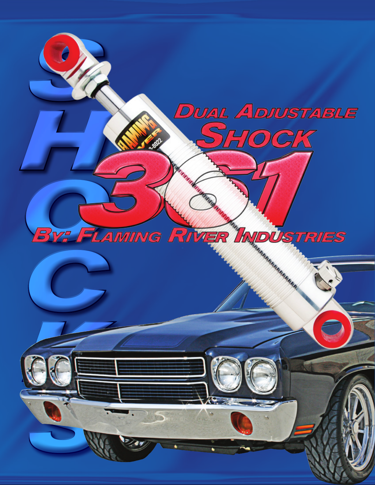
S
H
O
C
K
S
S
H
O
C
K
S
Page 2
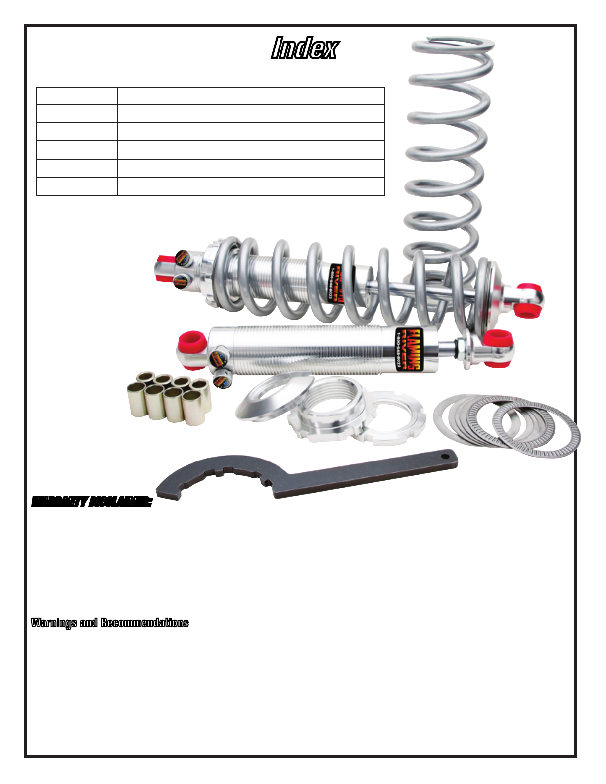
Page Number Section
1-4 GM Front Coil Over Installation
5-7 Front Smooth Body Shock Installation
7-8 Rear Smooth Body Shock Installation
8-11 Custom Coil Over Installation
12 Tuning and Adjustments
Index
WARRANTY DISCLAIMER:
Flaming River’s Limited Warranty
Flaming River warrants its products to be free from defects in material and workmanship for a period of one (1) year after the date of purchase,
except that: All steering columns are warranted for a period of three (3) years from the date of purchase. The Big Switch (part number FR1005) is
warranted for a period of three (3) years from the date of purchase, provided that it is not mounted with a steel bracket and provided further that
it is adequately protected from environmental conditions. All electrical products other than the Big Switch are warranted for a period of ninety (90)
days from the date of purchase. Flaming River’s warranty liability is limited to the replacement of defective products. Flaming River is not liable
for any labor costs associated with any warranty claim, or for any incidental or consequential damages. Improper installation, abuse, racing, and/
or modification of the products voids this warranty. No warranty of merchantability or fitness for a particular purpose is made by Flaming River with
respect to any of its products.
Warnings and Recommendations
It is the customer’s responsibility to determine the suitability of a given Flaming River product for the customer’s uses. Likewise, it is the customer’s
responsibility to install a Flaming River product. Contact the vehicle manufacturer whenever installing a switch to confirm the appropriateness of
using such a switch and the recommended placement of the switch on the vehicle. Use qualified chassis specialists for the installation of all steering
related components. Be aware that the installation of certain Flaming River products may adversely impact a
manufacturer’s warranty with respect to certain vehicles and other manufactured goods. Flaming River will repair or replace any product found to
be defective in material or workmanship. Improper installation, abuse, racing and/or modification VOID WARRANTY. Flaming River is not responsible
for any labor costs associated with any warranty.
Note: The information contained in this catalog is correct to the best of our knowledge and belief, having been compiled from reliable and official
sources of information. However, Flaming River Industries, Inc. cannot assume responsibility for possible error.
Page 3
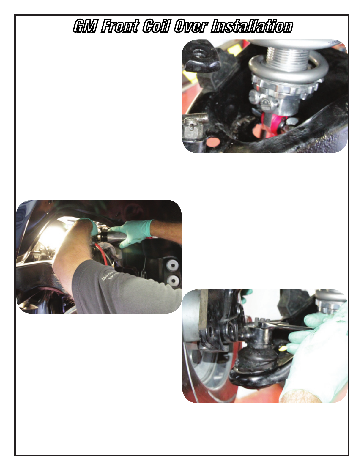
GM Front Coil Over Installation
1. Verify that your shocks are the correct lengths and mount style before beginning installation. Contact
your chassis builder, supplier or Flaming River if you have any questions.
2. Measure your vehicle’s ride height by measuring from the center point of the fender lip down to the
ground. Mark the spot you measured to for later reference.
3. Reference your vehicle’s owner’s manual to
determine the proper jacking locations, and the
instructions for removing the shocks and springs.
FAILURE TO FOLLOW THE INSTRUCTIONS CAN RESULT IN
SERIOUS INJURY OR DEATH.
4. Jack your vehicle up until the tires do not
touch the ground and the suspension hangs freely and
remove the wheels. Remove the shocks and sway bar
mounts, if applicable, and retain all mounting hardware.
5. Important: Ensure that factory or replacement
compression bumpers are in place and in good condition prior to installing the shocks. Also check other
components on the chassis such as bushings, ball joints, etc. and replace if needed.
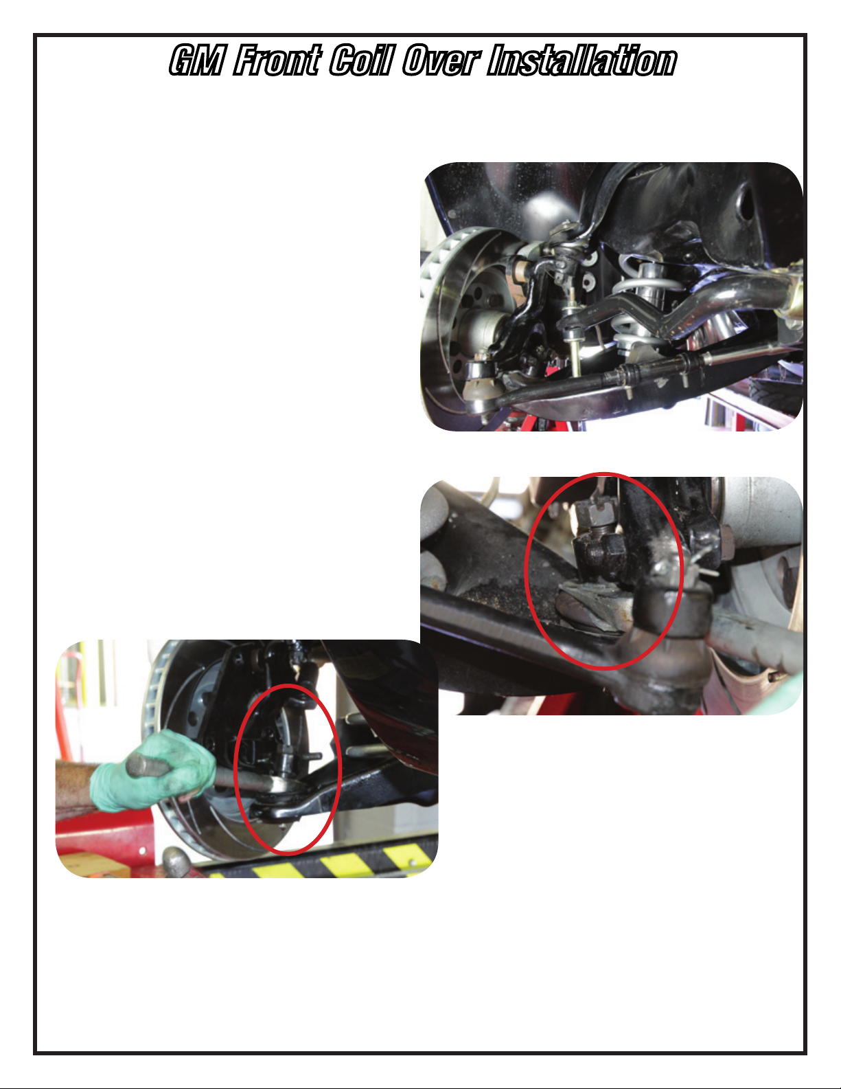
6. Use a floor jack to support the lower control
arm and remove the cotter pin and ball joint nut from
the lower ball joint. Loosen the ball joint stud from the
spindle using a tie rod / ball joint separator. Carefully
and slowly release the lower control arm assembly by
lowering the floor jack until the spring can be safely
removed
1
Flaming River Industries,Inc.
800 Poertner Dr. Berea, Ohio 44017
1-800-648-8022 • www.amingriver.com
Page 4
GM Front Coil Over Installation
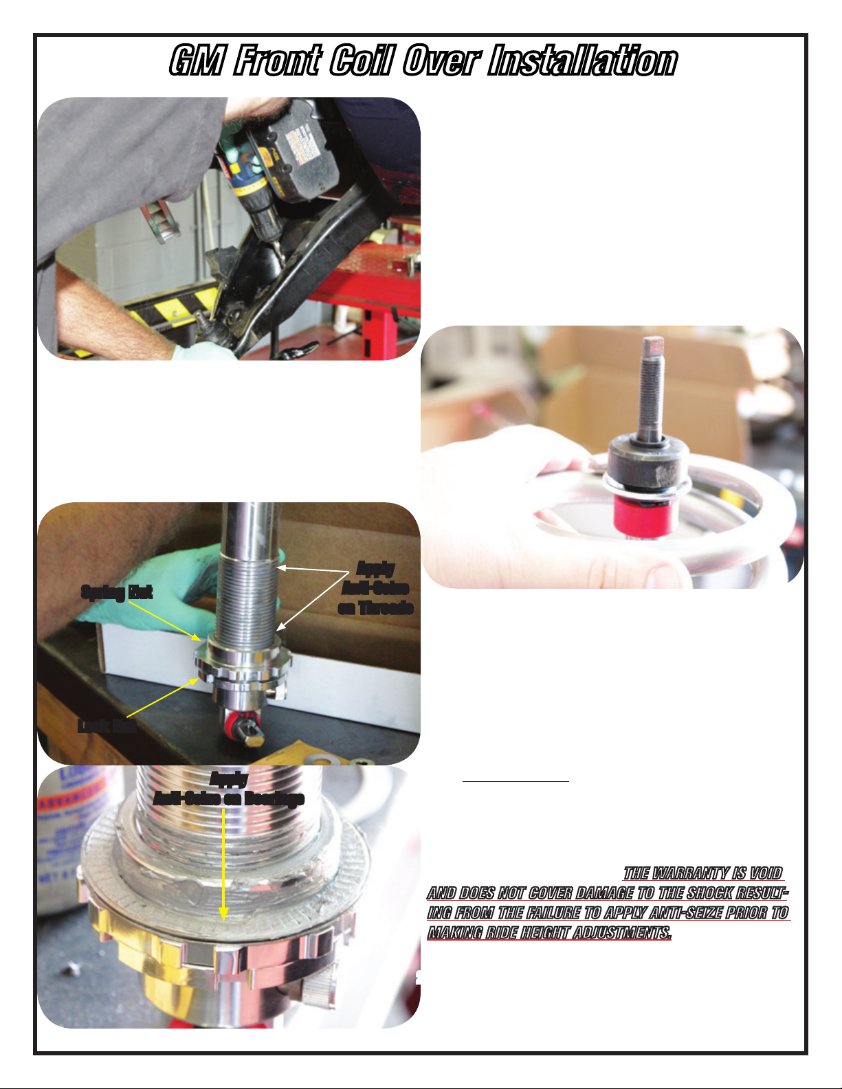
8. Install one stud washer and one bushing (half
of the shock stud bushing pack) onto the stud.
9. Fully extend the piston rod.
7. Remove the hardware that retained the stock
shock in the lower control arm. Clean the mounting
bolt holes thoroughly. You may need to slightly open
them using a file or 3/8” drill bit.
Spring Nut
Lock Nut
Apply
Anti-Seize on Bearings
Apply
Anti-Seize
on Threads
10. Screw the lock nut (shoulder up) and the spring
nut (shoulder up) down to the last thread only.
11. Apply anti-seize to the threads on the nuts and
the shock. If the Flaming River thrust bearing kit is
used
(recommended)
seize. Install the spring seat washer, then the bearing,
then the second washer. If you do not use the thrust
bearing kit, then coat one side of the washer supplied
with the shock with anti-seize and place it coated
side down on the spring nut.
AND DOES NOT COVER DAMAGE TO THE SHOCK RESULTING FROM THE FAILURE TO APPLY ANTI-SEIZE PRIOR TO
MAKING RIDE HEIGHT ADJUSTMENTS.
, coat both washers with anti-
THE WARRANTY IS VOID
2
Flaming River Industries,Inc.
800 Poertner Dr. Berea, Ohio 44017
1-800-648-8022 • www.amingriver.com
Page 5
GM Front Coil Over Installation
12. Install the spring onto the shock, putting the
small end of the spring over the shock body and down
onto the spring seat.
13. For GM Kits: Install the shock with the T-bar
on top of the lower control arm with the adjustment
knobs facing out toward the spindle utilizing the 3/8”
bolts and nylock nuts. Before tightening, ensure that
the shock is centered in the lower control arm.
14. For Mustang II Kits: If necessary, drill out the lower control arm bolt holes to the appropriate size depending on the shock style selected. If applicable, insert the bearing in a twisting motion. It may be necessary
to press the bearings into the shock. If so, do not press on the ball; press only on the race surrounding the ball.
Install snap rings on both sides of each bearing and ensure they are fully seated in the loops.
17. Reassemble the lower a-arm and the spindle.
Torque the spindle nut to factory specifications and
insert the cotter pin.
15. Jack the control arm up very slowly until the
shock stud extends through the factory mount while
vertically rotating the assembly and making sure that
the shock is not binding. You may need to also rotate
the spring until it is properly located in the factory
recesses.
16. Install the upper stud bushing, washer and nut.
3
Flaming River Industries,Inc.
800 Poertner Dr. Berea, Ohio 44017
1-800-648-8022 • www.amingriver.com
Page 6

GM Front Coil Over Installation
18. Adjust the spring nut up about 1/3 of the way
from the bottom of the threads on the shock.
19. Reattach the wheels and torque everything to the specifications defined by the vehicle’s manufacturer.
20. Verify that there is clearance around the coil-over shock and that the suspension does not bind at all,
even when wheels are turned to full lock position.
21. Carefully place the car on the ground to check clearances again. Lightly bounce the vehicle at each corner to verify that there are not any clearance issues.
22. Measure the ride height as you did prior to installation and ensure that there is sufficient travel in both
directions. Ideally, 60% of the shock stroke is available for compression. Adjust the ride height only with the
weight of the vehicle fully off of the tires.
DUE TO INCORRECT RIDE HEIGHT OR BY MAKING RIDE HEIGHT ADJUSTMENTS WITHOUT THE TIRES RAISED OFF THE
GROUND.
the extreme top or bottom of the threads, then you may need a softer or heavier spring.
23. Once ride height is correct, spin the lock nut up to the bottom of the spring nut and lock them together
using the two spanner wrenches.
24. It is important to note that your shocks should never be used as a travel limiter. Straps or cables made
for travel limitation should be used prevent topping out. Vehicles used in a manner where they could bottom out
the shocks (such as drag racing) should use a higher rate spring and a bump stop to help prevent shock damage. Any shock can be damaged from wheel stands despite bump stops.
25. Have your front end realigned upon completion of installation.
Raise or lower the ride height by adjusting the spring nut to achieve the desired ride height. If it is at
THE WARRANTY IS VOID AND DOES NOT COVER DAMAGE TO THE SHOCK
4
Flaming River Industries,Inc.
800 Poertner Dr. Berea, Ohio 44017
1-800-648-8022 • www.amingriver.com
Page 7

Front Smooth Body Installation
Please read these instructions carefully prior to installing your new Flaming River shocks.
Notes:
1. Verify that your shocks are the correct lengths and mount style before beginning installation. Contact
your chassis builder, supplier or Flaming River if you have any questions.
2. Measure your vehicle’s ride height by measuring from the center point of the fender lip down to the
ground. Mark the spot you measured to for later reference.
3. Reference your vehicle’s owner’s manual to determine the proper jacking locations, and the instructions
for removing the shocks and springs. FAILURE TO FOLLOW THE INSTRUCTIONS CAN RESULT IN SERIOUS INJURY OR
DEATH.
4. Jack your vehicle up until the tires do not touch the ground and the suspension hangs freely. Removing
the wheels is not required in all cases, but it does allow for easier access. Remove the shocks and sway bar
mounts, if applicable, and retain all mounting hardware.
5. Important: Ensure that factory or replacement compression bumpers are in place and in good condition
prior to installing the shocks.
DAMAGE TO THE SHOCK MAY OCCUR THAT IS NOT COVERED UNDER WARRANTY.
IF THE FACTORY BUMPERS OR EQUIVALENT ARE DAMAGED OR ARE NOT PRESENT,
6. It is important to note that your shocks are never to be used as a travel limiter. Severe damage will
result that will not be covered under the warranty. Straps or cables made for travel limitation should be used
prevent topping out. Vehicles used in a manner where they could bottom out the shocks (such as drag racing)
should use a higher rate spring and a bump stop to help prevent shock damage. Any shock can be damaged
from wheel stands despite bump stops.
1. If applicable, install one stud washer and one
bushing (half of the shock stud bushing pack) onto the
stud on the upper mount.
2. Confirm that the shocks will fit through the
lower control arms without modifications. If no, continue to step (3). If yes, put the shock through the
lower control arm and slide the upper shock mount
into place, tighten all nuts and bolts to factory specifications, and proceed to step (8).
5
Flaming River Industries,Inc.
800 Poertner Dr. Berea, Ohio 44017
1-800-648-8022 • www.amingriver.com
Page 8

Front Smooth Body Installation
3. Use a floor jack to support the lower control
arm, remove the cotter pin from the lower ball joint
and loosen the ball joint nut. Remove the ball joint stud
from the spindle using a tie rod / ball joint separator.
Carefully and slowly release the lower control arm assembly by lowering the floor jack until the spring can
be safely removed.
4. Fully extend the shock and put the T-bar
through the lower control arm and insert the bolts but
do not tighten them completely at this time. The knobs
on the shock should be facing out toward the spindle.
5. Slide the coil spring over the shock and align it
in the lower control arm. Align the upper shock mount
and the factory spring in the spring bucket. Jack the
lower control arm up very slowly, making sure that the
shock is not binding as the spring is compressed.
6. Install the upper stud bushing, washer and nut
and tighten the two control arm shock bolts to factory
specifications.
6
Flaming River Industries,Inc.
800 Poertner Dr. Berea, Ohio 44017
1-800-648-8022 • www.amingriver.com
Page 9

Front Smooth Body Installation
7. Reassemble the lower a-arm and the spindle.
Torque the spindle nut to factory specifications and
insert the cotter pin.
8. Reattach the wheels and verify everything has
been torqued to the specifications defined by the vehicle’s manufacturer.
9. Carefully place the car on the ground to check
clearances again. Lightly bounce the vehicle at each
corner to verify that there are not any clearance
issues.
10. Measure the ride height as you did prior to
installation and ensure that there is sufficient travel in
both directions. Ideally, 60% of the shock stroke will
be available for compression. INCORRECT RIDE HEIGHT
COULD RESULT IN DAMAGE TO THE SHOCK THAT IS NOT
COVERED UNDER WARRANTY.
Rear Smooth Body Installation
1. If applicable, install one stud washer and one
bushing (half of the shock stud bushing pack) onto the
stud on the upper mount.
Depending on application, you may
have a T-Bar or Stud on top of your
shock.
2. Mount the upper portion of the shock.
7
Flaming River Industries,Inc.
800 Poertner Dr. Berea, Ohio 44017
1-800-648-8022 • www.amingriver.com
Page 10

Rear Smooth Body Installation
3. Mount the lower portion of the shock to the
rear end housing. There should be little or no modifications necessary.
4. Make certain that everything is mounted securely then, if necessary jack the rear end housing into
the chassis. If applicable, make sure that the springs
are realigned.
5. Verify everything has been torqued to the
specifications defined by the vehicle’s manufacturer.
6. Carefully place the car on the ground to check
clearances again. Lightly bounce the vehicle at each
corner to verify that there are not any clearance issues.
7. Measure the ride height as you did prior to installation and ensure that there is sufficient travel in both
directions. Ideally, 60% of the shock stroke will be available for compression.
RESULT IN DAMAGE TO THE SHOCK THAT IS NOT COVERED UNDER WARRANTY.
INCORRECT RIDE HEIGHT COULD
Custom Coil Over Installation
1. Verify that your shocks are the correct lengths and mount style before beginning installation.
2. Measure your vehicle’s ride height by measuring from the center point of the fender lip down to the
ground. Mark the spot you measured to for later reference.
3. Reference your vehicle’s owner’s manual to determine the proper jacking locations, and the instructions
for removing the shocks and springs. FAILURE TO FOLLOW THE INSTRUCTIONS CAN RESULT IN SERIOUS INJURY OR
DEATH.
4. Jack your vehicle up until the tires do not touch the ground and the suspension hangs freely and remove
the wheels. Remove the shocks and springs and retain all mounting hardware.
5. Test fit your shocks into the chassis without mounting the springs. Move the suspension through the
entire travel range to ensure that it does not bind at any point.
6. Fully extend the piston rod and ensure that the jam nut under the bearing housing is secure.
8
Flaming River Industries,Inc.
800 Poertner Dr. Berea, Ohio 44017
1-800-648-8022 • www.amingriver.com
Page 11

Custom Coil Over Installation
7. Screw the lock nut (shoulder up) and the spring
nut (shoulder up) down to the last thread only.
8. Apply anti-seize to the threads on the nuts and
the shock. If the Flaming River thrust bearing kit is
used (recommended), coat both washers with antiseize. Install the spring seat washer, then the bearing,
then the second washer. If you do not use the thrust
bearing kit, then coat one side of the washer supplied
with the shock with anti-seize and place it coated
side down on the spring nut.
AND DOES NOT COVER DAMAGE TO THE SHOCK RESULTING FROM THE FAILURE TO APPLY ANTI-SEIZE PRIOR TO
MAKING RIDE HEIGHT ADJUSTMENTS.
THE WARRANTY IS VOID
Anti-Seize on Bearings
Spring Nut
Lock Nut
Apply
Apply
Anti-Seize
on Threads
9. Slide the spring over the shock, put the spring
cap into position (may require compressing the
spring), and adjust the spring nut up until the spring
is slightly compressed. Make certain that the spring is
seated squarely in the cap and on the spring nut. All
parts should be aligned.
9
Flaming River Industries,Inc.
800 Poertner Dr. Berea, Ohio 44017
1-800-648-8022 • www.amingriver.com
Page 12

Custom Coil Over Installation
10. Insert the proper poly sleeves or bearing
mounts into the shock ends. For bearing mount shocks,
insert the bearing in a twisting motion. It may be necessary to press the bearings into the shock. If so, do
not press on the ball; press only on the race surrounding the ball. Install snap rings on both sides of each
bearing and ensure they are fully seated in the loops.
11. Install the assembled coil-over on the vehicle
and adjust the spring nut up about 1/3 of the way from
the bottom of the threads on the shock.
Example shown was installed on the rear of
a 1940 Ford with a GM Rear End and Suspension.
10
Flaming River Industries,Inc.
800 Poertner Dr. Berea, Ohio 44017
1-800-648-8022 • www.amingriver.com
Page 13

Custom Coil Over Installation
12. Reattach the wheels and torque everything to the specifications defined by the vehicle’s manufacturer.
13. Verify that there is clearance around the coil-over shock and that the suspension does not bind at all,
even when wheels are turned to full lock position.
14. Remove the jack stands and carefully place the car on the ground to check clearances again. Lightly
bounce the vehicle at each corner to verify that there are not any clearance issues.
15. Measure the ride height as you did prior to installation and ensure that there is sufficient travel in both
directions. Ideally, 60% of the shock stroke is available for compression. Adjust the ride height only with the
weight of the vehicle fully off of the tires.
DUE TO INCORRECT RIDE HEIGHT OR BY MAKING RIDE HEIGHT ADJUSTMENTS WITHOUT THE TIRES RAISED OFF THE
GROUND.
the extreme top or bottom of the threads, then you may need a softer or heavier spring.
16. Once ride height is correct, spin the lock nut
up to the bottom of the spring nut and lock them
together using the two spanner wrenches.
Raise or lower the ride height by adjusting the spring nut to achieve the desired ride height. If it is at
THE WARRANTY IS VOID AND DOES NOT COVER DAMAGE TO THE SHOCK
17. Have your front end realigned upon completion
of installation.
11
Flaming River Industries,Inc.
800 Poertner Dr. Berea, Ohio 44017
1-800-648-8022 • www.amingriver.com
Page 14

TUNING AND ADJUSTMENT INSTRUCTIONS
Your Flaming River shocks have a total of 18 clicks plus a zero position of adjustment per knob, for a total of
361 different valving combinations. Compression and rebound are independently controlled on the Flaming River
shocks. The “C” knob adjusts compression, while the “R” knob adjusts rebound. Every Flaming River shock is
tested on a dynamometer prior to shipment to ensure that it is functioning properly. Manually moving a shock is
not an accurate testing method for ensuring that shocks are functioning properly.
Position zero is the softest setting and is found by turning the knob counterclockwise until the positive stop is
located. Position 18 is the stiffest setting. Only very light force is needed to adjust the knobs; do not ever force
the knob past its intended stop as doing so will damage the shock.
Recommended baseline points for adjusting your Flaming River shocks are as follows:
Drag Racing: Front: 12 - 18 compression; 0 - 4 rebound
Rear: 0 - 4 compression; 12 - 18 rebound
Handling: 7 - 12 compression; 7 - 12 rebound; 13+ for aggressive handling
Ride Quality: 2 - 6 compression; 2 - 6 rebound
12
Flaming River Industries,Inc.
800 Poertner Dr. Berea, Ohio 44017
1-800-648-8022 • www.amingriver.com
 Loading...