

Page 1

®
Flaming River Industries, Inc.® 800 Poertner Dr. Berea,Ohio 44017
440-826-4488 • Fax 440-826-0780 • Toll Free 1-800-648-8022
www.flamingriverhd.com
BATTERY CONTROL SAFETY SYSTEMS
5
0
0
A
M
P
K
I
L
L
S
W
I
T
C
H
TheThe
Page 2
2
Flaming River Industries 1-800-648-8022
P/N 102606 • Rev A • 06/06/17
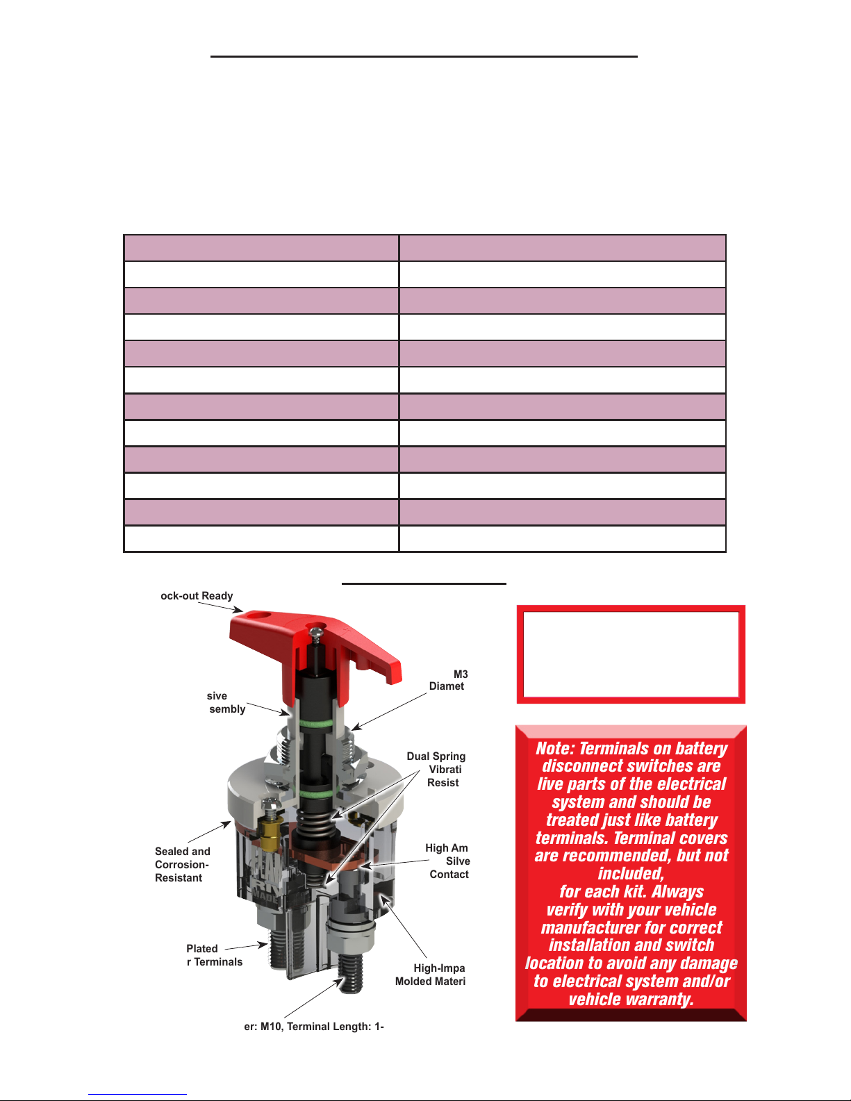
500 Amp Battery Disconnect Switch:
FR1046 The Big Switch 500 with Lock-Out Bracket
FR1046LED The Big Switch 500
with Lock-Out Bracket & LED Indicator
FR1047 The Big Switch 500 Lock-Out Hole
with Lever Handle w/ Retrot Diamond Bracket
Voltage 12V/24V
Max Continuous Current 500 Amps
Environmental Protection Rating IP65
Corrosion Resistant Yes
Operating Temperature -40°F to + 176°F (-40°C to +80°C)
Switch Body Material Glass-filled nylon
Internal Contacts AgSnO2 (Silver Tin Oxide) Plated Copper
Contact Terminals AgSnO2 (Silver Tin Oxide) Contacts
Stud Diameter M10
Available Stud Length 1.18 in (1-3/16 in)
Contact Hardware Nickel-plated brass
M10 Tightening Torque 11-13 ft·lbs
Note: Terminals on battery
disconnect switches are
live parts of the electrical
system and should be
treated just like battery
terminals. Terminal covers
are recommended, but not
included,
for each kit. Always
verify with your vehicle
manufacturer for correct
installation and switch
location to avoid any damage
to electrical system and/or
vehicle warranty.
Non-Corrosive
Plunger Assembly
High Amp
Silver
Contacts
Lock-out Ready
Sealed and
Corrosion-
Resistant
Dual Springs/
Vibration
Resistant
M30
Diameter
High-Impact
Molded Material
Silver-Plated
Copper Terminals
Terminal Diameter: M10, Terminal Length: 1-3/16”
Switch Features
(Lock
not Included)
To activate switch,
push handle down
while turning
Page 3
3
Flaming River Industries 1-800-648-8022
P/N 102606 • Rev A • 06/06/17
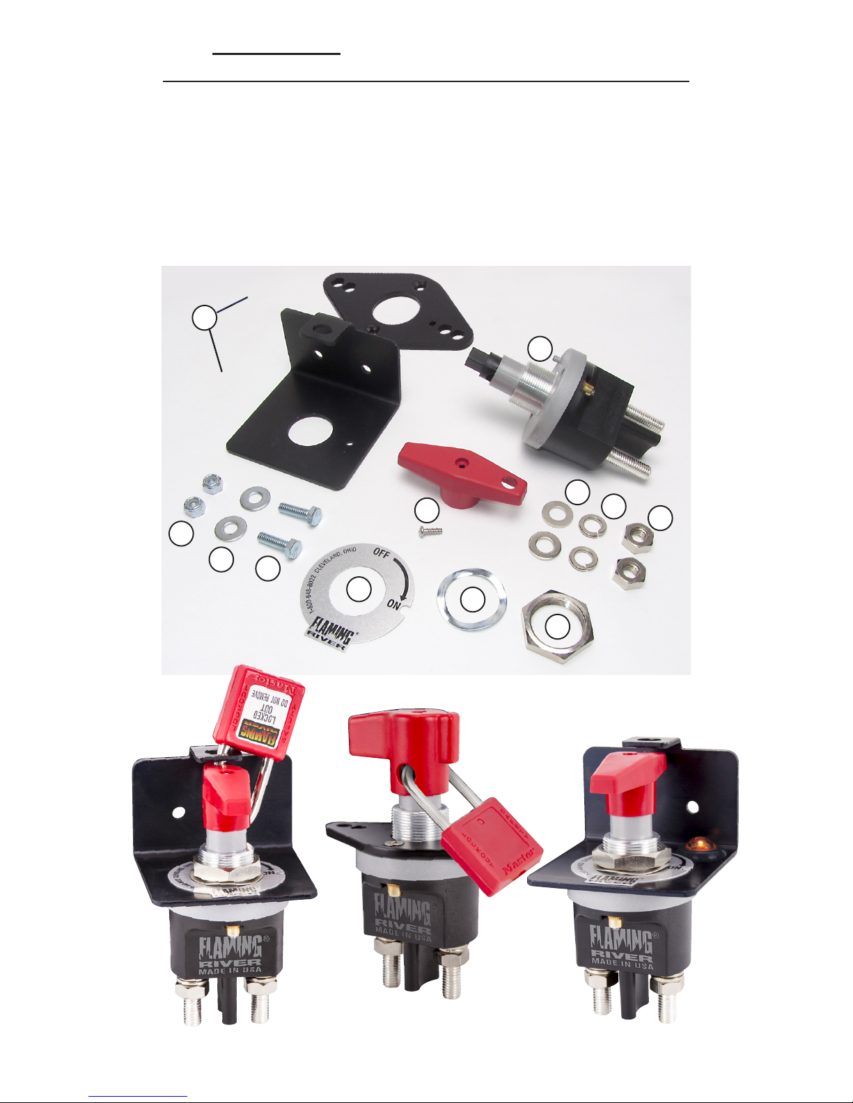
Item No. Description Qty
1.................... Switch Assembly ........................................................................... 1
2.................... Switch Bracket ................................................................................ 1
3.................... Switch Handle/Screw ...................................................................... 1
4.................... Off/On Logo Tag .............................................................................. 1
5.................... Wave Washer .................................................................................. 1
6.................... M30 Hex Nut ................................................................................... 1
7.................... 1/4”-20 x 7/8” Hex Cap Screw ....................................................... 2
8.................... 1/4” Flat Washer ............................................................................. 2
9.................... 1/4”-20 Nylock Nut ......................................................................... 2
10.................. Hex Nut for Terminal Stud .............................................................. 2
11 .................. Lock Washer for Terminal Stud ..................................................... 2
12.................. Flat Washer for Terminal Stud ...................................................... 2
1
3
4
8
7
11
6
9
2
5
12
10
FR1046
FR1047
FR1046
FR1047
FR1046LED
(Lock
not Included)
Kit Contents (Varies based on part number)
Page 4

4
Flaming River Industries 1-800-648-8022
P/N 102606 • Rev A • 06/06/17
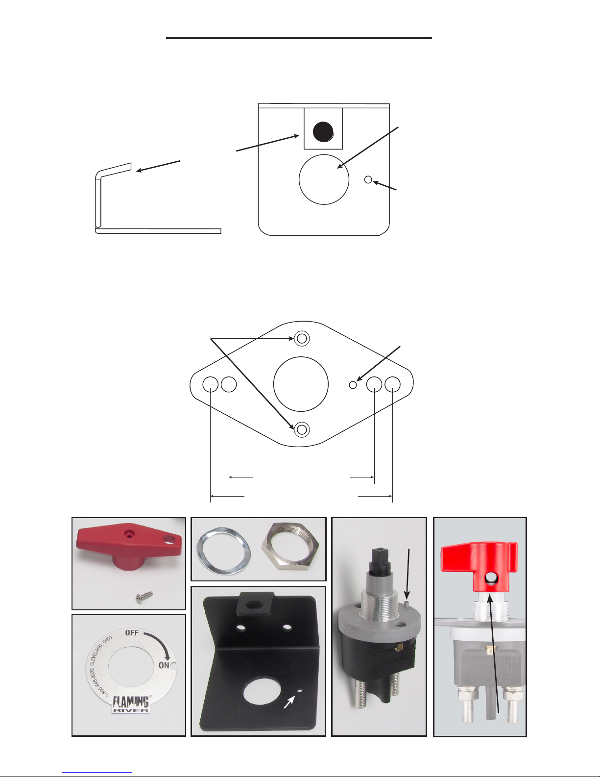
Switch and Bracket Assembly
(Refer to diagrams on following page)
FR1046/FR1046LED
1. Place the red T-handle (A) on top of the switch (F) and turn
clockwise to turn the switch ON and remove the T-handle.
2. Remove the M30 hex nut (C) and wave washer (B) from the
packaging.
3. Insert the neck of the switch (F) into the mounting bracket hole
(E) and slide on the ON/OFF plate (D), wave washer (B), and
M30 hex nut (C).
4. Tighten the hex nut (C) until the wave washer (B) is completely
at. Do not tighten the nut more than 7-10 ft.·lbs. Make sure the
tab on the gray switch (F) top ts into the small alignment hole.
The top of the gray switch (F) should be ush against the bottom
of the bracket (E).
5. Install the T-handle (A) on the shaft of the switch. Insert and
tighten the Phillips head screw into the handle. Rotate the switch
to the OFF position by turning the handle counter-clockwise.
FR1047
1. Diamond bracket is already properly installed on your FR1047
Battery Disconnect Switch.
2. Using the information in gure 2, determine the desired
mounting hole width: either 3.15” (80 mm) or 3.94” (100 mm)
spacing.
3. Install the switch in the vehicle and the lever style handle (G)
onto the top of the switch shaft with the supplied phillips head
screw.
A
D
Figure 1 (Lock-Out Bracket)
Lockout
Bracket
Switch
Mounting Hole
Locating Tab Hole
Top View
Figure 2 (Diamond Bracket)
Switch
Mounting Hole
Switch
Mounting Holes
Locating Tab Hole
Mounting Holes:
3.15” (80 mm)
3.94” (100 mm)
Page 5
5
Flaming River Industries 1-800-648-8022
P/N 102606 • Rev A • 06/06/17
A
B
C
D
E
F
Alignment Hole
Alignment Tab
Figure 1 (Lock-Out Bracket)
Lockout
Bracket
Switch
Mounting Hole
Locating Tab Hole
Top View
Figure 2 (Diamond Bracket)
Switch
Mounting Hole
Switch
Mounting Holes
Locating Tab Hole
Mounting Holes:
3.15” (80 mm)
3.94” (100 mm)
Switch and Bracket Assembly (cont.)
G
Page 6

6
Flaming River Industries 1-800-648-8022
P/N 102606 • Rev A • 06/06/17
Electrical Connections
Make sure you have properly mounted the switch with the included
attachment hardware before installing cables, wiring, or making
electrical connections. Remove the positive and negative cables
connected to the battery before proceeding. This is for the installer’s
safety. No part of the vehicle should be energized while installing the
switch. The Big Switch 500 Series battery disconnect switches can
be used to disconnect either the positive or negative terminals of the
battery. Verify installation and wiring with the vehicle’s manual
and follow all vehicle manufacturer instructions.
1. Select two battery cables of required length for the installation.
Cable gauge size will be at the installer’s discretion depending
on vehicle requirements and specications. If the installer
wishes to cut and reuse the original battery cable, make sure
that there is enough cable to reach the switch without stressing
the cable or the battery disconnect switch.
2. Attach the two cable ends to the switch terminals as shown in
below. Tighten the M10 nuts until the lock washers atten, but
no tighter than 11-13 ft.·lbs.
3. Once the cables are installed and tightened, terminals covers
(recommended, but not included) should be applied to the
switch terminals.
4. Make sure the The Big Switch 500 is turned to the OFF position.
Connect the load-side cable to the required point on your
vehicle FIRST. Hook up the cable that connects directly to the
battery terminals SECOND. See below for clarication.
5. Turn ON The Big Switch 500 and make sure your vehicle is
powered.
FR1003TM Terminal Covers
Sold in sets of two. Can be used to
cover cables on all Battery Disconnect
Switches. Sold separately from switch.
Page 7

7
Flaming River Industries 1-800-648-8022
P/N 102606 • Rev A • 06/06/17
Connection of the LED indicator should be completed at the time
the switch is mounted but before battery cables are connected
to the switch. Do not install the switch or LED indicator while the
vehicle battery is connected to the vehicle. Make sure that the area
of the chassis where the bracket is mounted has a good connection
to ground and is not insulated by plastic or paint. If this is not
possible, an additional wire should be run directly to the WHITE
ground wire to complete the circuit.
1. Make sure that the switch is installed in the bracket and mount
the switch in the desired location. Only screw on ONE of the
lock nuts.
2. Take the WHITE wire with the smaller eyelet and slide it over
the right screw. Tighten down the right lock nut so that the eyelet
is pressed rmly against the vehicle chassis for a proper ground
connection.
3. Take the BLACK wire with the large eyelet and slide it over the
screw terminal that is connected to the VEHICLE LOAD.
4. Before proceeding, make sure the battery disconnect switch is
in the OFF position.
5. Connect the vehicle load side battery cable, followed by the
battery side battery cable, and secure these connections with
the provided M10 washers, lock washers, and nuts.
6. Connect your battery cables to the positive and negative battery
terminals and test your newly installed switch.
LED Indicator Wiring Instructions (FR1046LED Only)
DO NOT ATTEMPT TO OVER
TIGHTEN THE BASE TO THE
HOUSING (7-10 FT. LBS Max..)
THIS WILL VOID WARRANTY
Battery
Cable
Positive or Negative
Terminal
Cable
Figure 3
Nickel-Plated Brass Fasteners
Connect
First
Connect
Second
To Vehicle
Load
LED Only
To
Bracket
White (neg.)
Black (pos.)
Page 8

Flaming River Ind.
800 Poertner Dr
Berea, OH 44017
800-648-8022
WARRANTY DISCLAIMER: Flaming River’s® Limited Warranty
Flaming River® warrants its products to be free from defects in material
and workmanship for a period of one (1) year after the date of purchase,
except that: The Big Switch (part number FR1046/FR1047) is warranted
for a period of three (3) years from the date of purchase, provided that it is
not mounted with a steel bracket and provided further that it is adequately
protected from environmental conditions. All electrical products other
than the Big Switch are warranted for a period of ninety (90) days from
the date of purchase. Flaming River’s® warranty liability is limited to the
replacement of defective products. Flaming River® is not liable for any
labor costs associated with any warranty claim, or for any incidental or
consequential damages.
Improper installation, abuse, racing, and/or modication of the products
voids this warranty. No warranty of merchantability or tness for a particular
purpose is made by Flaming River® with respect to any of its products.
Warnings and Recommendations
It is the customer’s responsibility to determine the suitability of a given
Flaming River® product for the customer’s uses. Likewise, it is the
customer’s responsibility to install a Flaming River® product. Contact
the vehicle manufacturer whenever installing a switch to conrm the
appropriateness of using such a switch and the recommended placement
of the switch on the vehicle.
Use qualied chassis specialists for the installation of all steering related
components. Be aware that the installation of certain Flaming River®
products may adversely impact a manufacturer’s warranty with respect to
certain vehicles and other manufactured goods. Flaming River will repair
or replace any product found to be defective in material or workmanship.
Improper installation, abuse, racing and/or modication VOID WARRANTY.
Flaming River® is not responsible for any labor costs associated with any
warranty.
 Loading...