

Page 1

Page 2

Rack & Pinion Cradle System
Thank you for your interest in Flaming River products. We hope you enjoy your rack and pinion cradle
system.
The product that you have selected has been built and designed for improved driving comfort and
convenience. No drilling welding or grinding is necessary.
All systems have been created on stock chassis with little or no change to the original suspension, engine,
or transmission.
Quality grade fasteners and materials are used to allow normal installation. We do recommend new outer
tie rod ends and a professional alignment.
Thanks again,
Jeanette Ladina
Jeanette Ladina
President
Page 3

Rack & Pinion Cradle System
Index
For safety disconnect battery cables and ensure that vehicle is properly supported by jack stands.
NOTE: Hoses (FR1610) Pump Mounting Brackets (FR1611) is sold separately and is not included in this
kit. Chevelle Outer Tie Rod Ends ES333RL and adjuster sleeves ES2032S must be used with this rack
and pinion kit.
Before paint or powder coating of the rack and pinion cradle system we recommend that you prefit the
system to ensure proper fit.
Installation hardware and inventory PG 2
Electrical System Verification PG 3
(Only if using a Flaming River Column)
Removal of Factory Steering Shaft PG 4
Removal of Factory Steering Column PG 4
(Only if using a Flaming River Column)
Steering Box & Linkage Removal PG 6
Installation of Flaming River Column (For kits including new Column)
Installation of New Flaming River Tilt Column PG 7
Electrical System Notes PG 8
Steering Wheel Installation PG 9
Installation of the Flaming River Rack & Cradle
Installation of Rack and Cradle PG 10 - 11
Section 4 Universal Joint Installation
A. Universal Joint and Steering Shaft Installation PG 12 -13
Torque Specs PG 12
Because of their intended usage, the manufacturer makes no warranties whatsoever express or implied, oral or written, to purchasers of their
products regarding performance, safety, fit merchantability, or length of service. Purchasers are responsible for selection of proper goods and
must rely on there own skill or judgment that such goods are suitable for purchasers application.
Warranty Disclaimer
1
68-72 GM A Body
Power Steering
01/15/07
Page 4
Rack & Pinion Cradle System
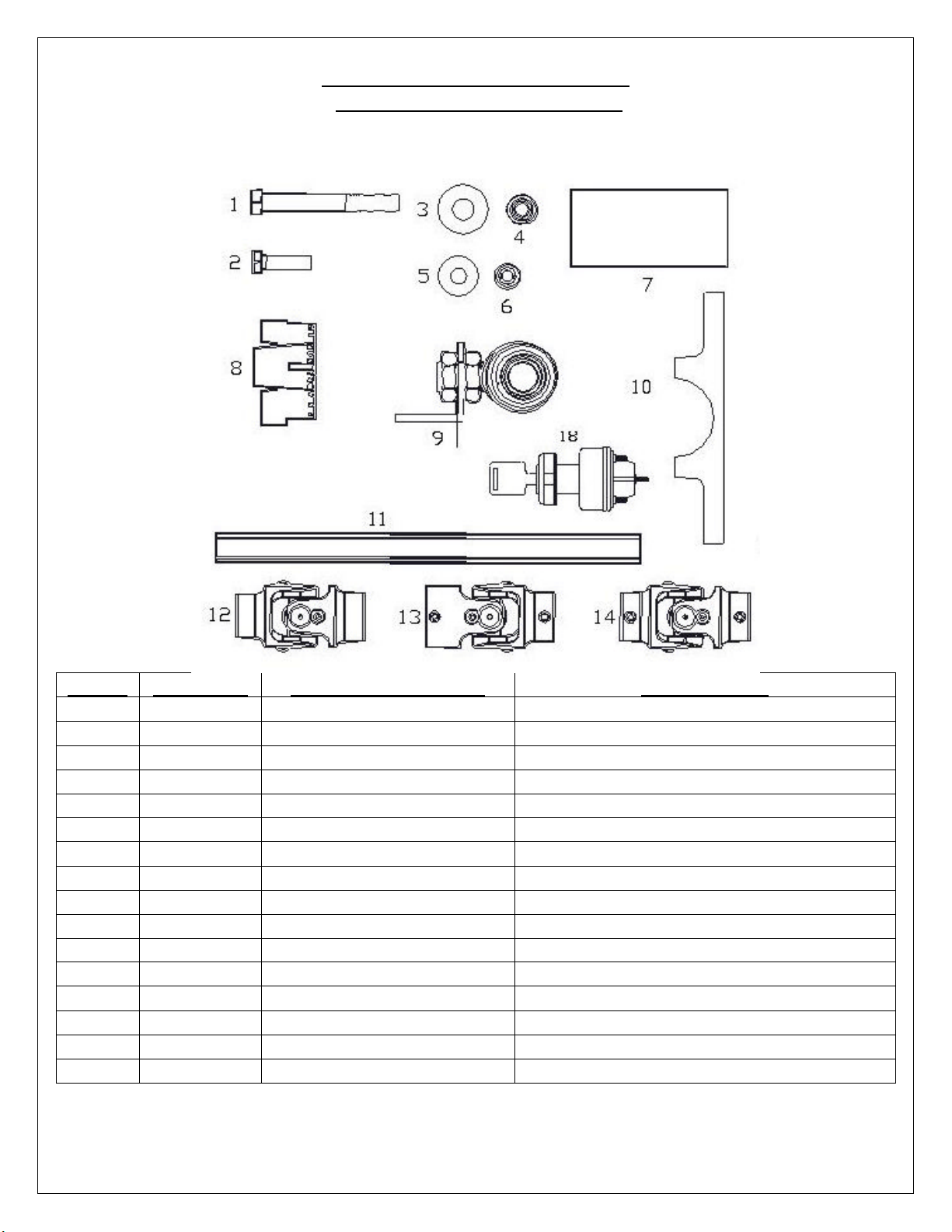
Installation Kit Hardware Package
ITEM # QUANTITY SIZE / PART NUMBER DESCRIPTION
1 3 7/16-14 x 4 1/2" Driver's Side Cradle Mounting Bolts
2 2 3/8-16 x 1 1/4" Passenger Side Cradle Mounting Bolts /
3 6 7/16 Washers Washers for 7/16 Mounting Bolts
4 3 7/16-14 Lock Nuts Locking Nuts for 7/16 Mounting Bolts
5 4 3/8 Washers Washers for 3/8 Mounting Bolts
6 2 3/8-16 Lock Nuts Locking Nuts for 3/8 Mounting Bolts
7 2 FRBSH2 Floor Mount Bushing (Column Kits Only)
8 1 FR20118 Wiring Adapter (Column Kits Only)
9 1 FR1810 & BK10500 Support Bearing and Bracket
10 1 FR20114 Column Dash Mount (Column Kits Only)
11 1 FR1850-22 22" DD Shaft
12 1 FR1924 9/16-26 X ¾-DD Chromemolly U-Joint
13 1 FR1934 1"DD x 3/4"DD Chromemolly U-Joint
14 1 FR1920 3/4"DD x 3/4"DD Chromemooly U-Joint
17 1 FR20006 OR FR20006SS Column (Column Kits Only)
18 1 FRIGN1 Ignition Switch (Column Kits Only)
2
68-72 GM A Body
Power Steering
01/15/07
Page 5
Rack & Pinion Cradle System
If using a Flaming River Steering Column it is recommended that before any disassembly you should first
verify the wiring for your turn signals and ignition switch to ensue proper operation.
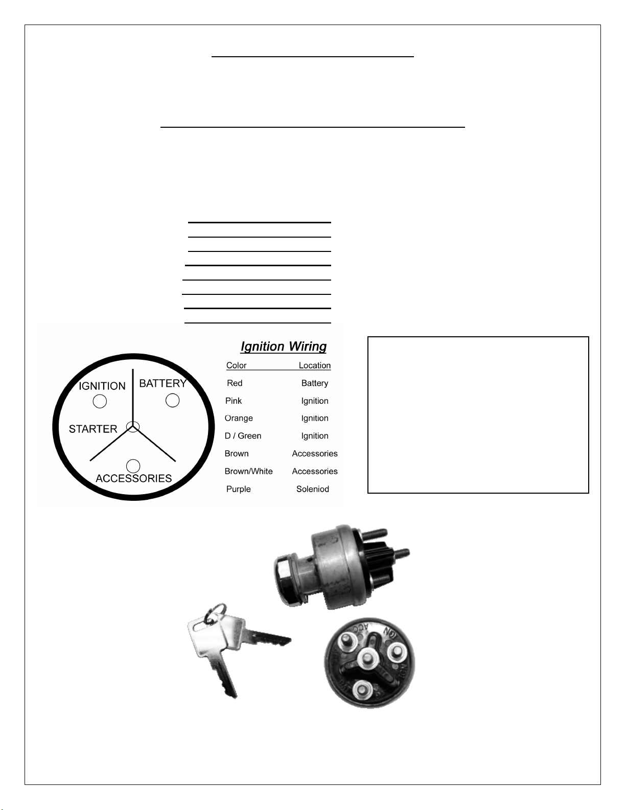
Color Verification to be completed before disassembly
Before disconnecting the turn signal and the ignition connectors verify the wiring color to ensure proper
operation. The colors listed with the ignition switch diagram below are from a stock wiring system. Wire
colors may change due to the use of aftermarket wiring harnesses and wiring modifications. The use of a
wiring diagram is recommended.
Brake Light Switch :
RR Turn Signal :
LR Turn Signal :
Turn Signal Power :
Hazard Power :
RF Turn Signal :
LF Turn Signal :
Horn :
Ignition Switch
Included in Kit
The ignition switch included with this kit
is not located in the steering column
and will have to be relocated in the
interior of the vehicle. Ex. Dash board,
center console or hidden.
If lengthening the ignition wiring be
sure to use proper gauge wire to
ensure proper function and safety.
3
68-72 GM A Body
Power Steering
01/15/07
Page 6

Rack & Pinion Cradle System
Original Steering Shaft Removal
1) Remove the pinch bolt that retains the steering coupler to the steering column and the bolt that
retains the rag joint to the steering box. Collapse shaft and remove it from the car.
Original Column Removal
Only perform these steps if using a new Flaming River Steering Column
1) Disconnect the column wiring connectors.
2) Remove the bolts that hold the column floor mount to the firewall.
3) Support the column and remove the bolts that retain the under dash mounting clamp.
4) Remove the factory steering column from the vehicle.
4
68-72 GM A Body
Power Steering
01/15/07
Page 7

Rack & Pinion Cradle System
Steering Box and Linkage Removal
Before beginning you must first measure the width of your front end from LEFT outer tie rod end zerk to the RIGHT outer tie rod
end zerk to determine the overall width of your front end. Write dimension here for further reference
1) Remove the pitman arm from the steering box using a pitman arm puller.
2) Remove the two bolts that retain the idler arm to the frame rail.
3) Remove the cotter pins and castle nuts and separate the outer tie rod ends from the spindles.
5
68-72 GM A Body
Power Steering
01/15/07
Page 8

Rack & Pinion Cradle System
4) Next remove the steering linkage from the car.
5) If you have power steering remove the lines from your power box, pump and pump brackets.
6) Remove the three bolts that retain the box to the frame rail and remove the box from the car
6
68-72 GM A Body
Power Steering
01/15/07
Page 9

Rack & Pinion Cradle System
Installation of Flaming River Column
1) Install one the rubber isolator strips into the original dash mounting location in-between the dash
and the new steering column.
2) Hold the new column into the mounting location and using the original column mounting screws
tighten the new column mounting clamp to hold the column in place.
3) Install
rubber isolator into the original floor mount and then slide it over the column tube. Slightly snug
clamp.
4) Place the column under the dash and snug the two mounting screws for the under dash mount.
7
68-72 GM A Body
Power Steering
01/15/07
Page 10

Rack & Pinion Cradle System
Color Verification to be completed before disassembly
5) Install the floor mounting screws and tighten to 15 ft lbs.
6) Ensure that the column straight by having the turn signal arm points to the 9 o’clock position.
Tighten the two mounting screws on the new Flaming River clamp. ( see photo B)
7) Tighten the floor mounting clamp around the tube. (see photo A)
8) Install the wiring jumper harness.
Electrical System Notes
Caution: Before disconnecting your original steering column wiring harness please verify each
wire color and function on the worksheet below. Some wire colors may vary from year to year.
FLAMING RIVER COLUMN WIRING
P-WHITE-BRAKELIGHT SWITCH
N-DK GREEN-RR TURN SIGNAL
M-YELLOW-LR TURN SIGNAL
L-PURPLE-TURN SIGNAL POWER
K-BROWN-HAZARD POWER
J-DK BLUE-RF TURN SIGNAL
H-LT BLUE-LF TURN SIGNAL
G-BLACK-HORN
Brake Light Switch :
RR Turn Signal :
LR Turn Signal :
Turn Signal Power :
Hazard Power :
RF Turn Signal :
LF Turn Signal :
Horn :
68-72 GM A Body
Power Steering
8
01/15/07
Page 11

Rack & Pinion Cradle System
Steering Wheel Installation
1) Install horn contact kit into canceling cam tube and turn to lock.
2) Align steering wheel adapter so that the canceling cam hole is at approx the 11 o’clock position and
that one of the steering wheel mounting holes is at the 12 o’clock position.
3) To install the wheel adapter run the horn contact wire through the hole for the canceling cam and
place the adapter on to the splined column shaft.
4) Tighten the adapter-retaining nut until the adapter is approximately 1/16” away from the column
shroud.
9
68-72 GM A Body
Power Steering
01/15/07
Page 12

Rack & Pinion Cradle System
Installing Bolts
into Frame Rail
Tighten All
Installation of the Flaming River Rack and Cradle
1) Install the rack and pinion cradle by sliding it into place between the frame rails, installing the new
hardware using three 7/16” bolts where the gear box was mounted and two 3/8” bolts where the idler
arm was located. Tighten the 7/16” nuts and bolts to 50-65 ft lbs and the 3/8” nuts and bolts to 40 -45
ft lbs.
Installing Cradle In-between Frame Rails
Nuts & Bolts
2) To install the Flaming River rack and travel bar system rotate the travel bar over the lip of the cross
member, next position the rack into place and install the rack to the cradle using the mounting
brackets provided. Once you have adjusted the pinion angle tighten the 4 mounting bracket bolts and
the 2 ¼-20 set screws to lock the rack in place.
10
68-72 GM A Body
Power Steering
01/15/07
Page 13

Rack & Pinion Cradle System
3) Install the OEM adjuster sleeves onto the new Flaming River inner tie rod ends, next install the outer
tie rod ends into the adjuster sleeves and adjust tie rods until the original zerk to zerk measurement
taken before disassembly is obtained. Measurement from the index page.
4) To install the outer tie rod ends into the spindles you must load the front suspension. (Securely placing
jack stands under the lower control arms and lowering the car onto the jack stands accomplishes this.)
Install the outer tie rod ends into the spindle and tighten the castle nuts to 30-40 ft lbs. Make sure to
install cotter pins into the castle nut and tie rod end and bend the tabs over for security.
11
68-72 GM A Body
Power Steering
01/15/07
Page 14

Rack & Pinion Cradle System
Universal Joint System.
1) Install support-bearing mount onto the rear control arm bolt. (Picture below). Note: The angle of this
mount is set for most applications. Some adjustment may be necessary for the correct angle and ujoint alignment.
2) We recommend the use of ¾” wood dowel rod to mock up the steering shaft to obtain the correct
length of the shafts.
3) Install your shaft kit and snug each set screw so that it will leave a mark in the shafts.
4) Remove shaft and dimple each setscrew mark using a ¼” drill bit. (As shown below.)
Continued on Next Page
12
68-72 GM A Body
Power Steering
01/15/07
Page 15

Rack & Pinion Cradle System
5) Re-install the shafts using red loc-tite thread locker on the set screw threads. Tighten each setscrew
to 25 ft. lbs. Tighten all lock nuts securely. We recommend that you Inspect setscrews periodically for
tightness.
Torque Specs
Cradle to Frame Mounting Bolts
7/16” Mounting Bolts 50-65 ft lbs
3/8” Mounting Bolts 40-45 ft lbs
Outer Tie Rod Ends to Spindle 30-40 ft lbs
Universal Joint Set Screws 25 ft-lbs
13
68-72 GM A Body
Power Steering
01/15/07
 Loading...