

Page 1

800 Poertner Dr. Berea, OH 44017 800 - 648 - 8022
Page 2

Index
NOTE:
tie rod end zerk to determine the overall width of your front end. Write dimension here for further referen ce
Parts Inventory
Section 1 Original System Removal
A. Original Column & Wheel Removal PG 3
B. Steering Box & Linkage Removal PG 3
Section 2 Installation of Flaming River Column
Section 3 Installation of the Flaming River Rack & Cradle
A. Installation of Manual Rack & Pinion Cradle PG 7
B. Installation of Manual Rack & Pinion
C. Installation of Power Rack & Pinion Assembly PG 9
D. Installation of Power Rack & Pinion Universal
D. Installation of Power Steering Pump PG 10
Section 5 Bleeding System
A. Bleeding the power steering PG 11
Torque Specs PG 11
Note:
Note:
We recommend
We recommend
Note:
Note:
Before beginning you must first measure the width of your front end from LEFT outer tie rod end zerk to the RIGHT outer
PG 2
A. Installation of New Flaming River Tilt Column PG 3-4
B. Installation of original wheel
C. Installation of aftermarket wheel PG 5-6
D. Connecting Electrical System PG 6
Universal Joint System PG 8
Joint System PG 9-10
For safety disconnect battery cables and ensure that vehicle is properly supported by jack stands.
65-66 Mustangs with V8 and power assist need to replace outer tie rods using manual V8 outer tie rod end.
a professional alignment to set the proper alignment settings.
that you always install new outer tie rod ends when installing this kit.
**** The use of Flaming River Headers maybe necessary with use of the Power Rack and Pinion System. ****
Flaming River Recommends that you use Dextron or high grade power steering fluid.
PG 4-5
Warranty Disclaimer
All parts are sold without any express or implied warranty of merchantability as to fitness for the intended purpose. Flaming River
Industries, Inc. disclaims all liability for any damage or personal injury which may arise or result from the sale, installation or use of
any products. The installation of the products may adversely impact a manufacturer’s warranty with respect to certain vehicles and
other manufactured goods. It is the customer’s responsibility to select appropriate parts for the application. The disclaimer is
limited only by applicable state laws. Flaming River recommends using qualified chassis specialists for installation of all steering
related components. Flaming River will repair or replace any product found to be defective in material or workmanship. Improper
installation, abuse, racing and or modification void warranty. Flaming River is not responsible for any labor costs associated with
any warranty.
Page 1 of 11
Updated on 12 July 2010
rd/jj
Page 3
Qty Part No. Description Notes
2 BOLT-3/8-16X3.5 3/8-16 Grade 8 Bolt 3.5" long
2 NUT-3/8-16 Nylock Lock Nut 3/8-16
4 WASH-3/8 3/8" Flat Washer
3 BOLT-7/16-14X3.5 7/16-14 Grade 8 Bolt 3.5" Long
3 NUT-7/16-14 Nylock Lock Nut 7/16-14
6 WASH-7/16 7/16" Flat Washer (6) 7/16 Flat Washers for Mounting of Cradles
2 BOLT-3/8-16X1 3/8-16 Grade 8 Bolt 1" long Manual Kit Only Passenger Side Rack Mount
2 BOLT-3/8-16X1.5 3/8-16 Grade 8 Bolt 1.5" Long Manual Kit Only Driver's Side Rack Mount
4 NUT-3/8-16 Nylock Lock Nut 3/8-16 Manual Kit Only Mounts Manual Rack to Cradle
1 FR1507C Manual Rack Mounting Clamp Manual Kit Only
1 FR1850 18" DD Shaft
1 FR20099-2 67-70 Floor Mount
1 FR65MUMT 65-66 Floor Mount
1 FRBSH-1 Mustang Column Mount Bushing
2 Screw-10 #10 x 3/8" Hex Head Metal Screw
2 NUT-11/16-18 11/16-18 Jam Nut
1 FRM16X6AN M16-1.5 X 6 AN Fitting Power Only
1 FRM14X6AN M14 -1.5 X 6 ANFitting Power Only
1 BK10200 Support Bearing Bracket Bent Manual Kit Only
1 FR1810-2 3/4 Zinc Support Bearing Manual Kit Only
1 FR20118 Female Wiring Adapter
1 FRHRN2 Horn Relay
1 FR300MUCOL
1 FR300COL
1 FR1614 Power Steering Reservior Power Only
1 FR1789P 3/4 DD x FR Power Billet U-Joint Power Only
1 FR1934 3/4 DD x 1" DD Chromemoly U-Joint Power Only
1 FRMBPW1 P/S Steering Pump Bracket Power Only
1 100480
1 FRPMPSB-V Pump w/ V-Belt Pulley Power Only
1 FR1507-3Q-3 Manual Rack and Pinion Manual Only
1 FR1709DD 9/16-26 x 3/4DD U-Joint Manual Only
1 FR1716DD 3/4 DD x 3/4DD U-Joint Manual Only
1 FR1717DD 1 DD x 3/4 DD U-Joint Manual Only
1 FRM5-MU65H Manual Cradle Manual Only
29" Column For Original Wheel (Ford
Spline)
29" Column for Aftermarket Wheel
(GM Spline)
Power Rack & Pinion Cradle
Assembly
Only in Kits for Original OEM Steering Wheel
Only In Kits for AfterMarket Steering Wheels
Power Only
Page 2 of 11
Updated on 12 July 2010
rd/jj
Page 4
Original Column Removal
64 ½ - 67 Long Shaft Steering Box Column Removal
1) Remove horn button by pushing down on horn hub and turning counter clockwise.
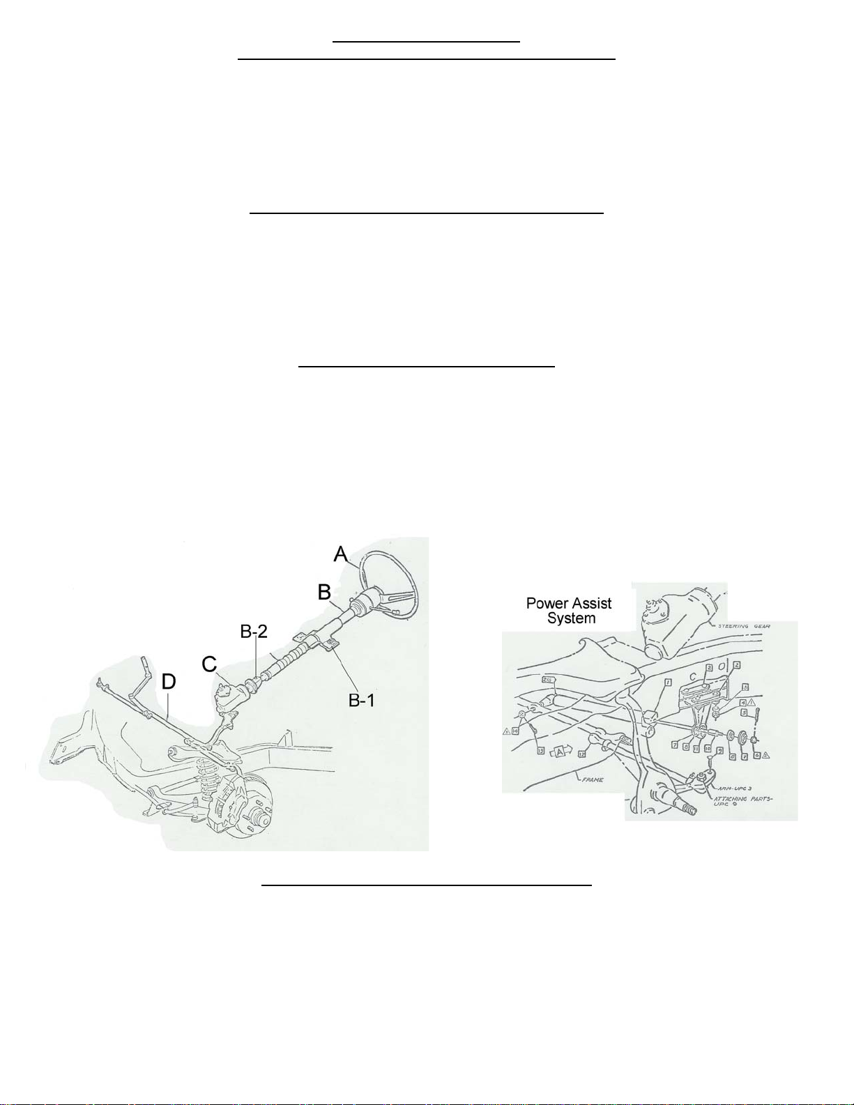
2) Remove steering wheel retaining nut and remove steering wheel (A) by using a steering whe el puller.
3) Disconnect the electrical plug towards the base of the column (B).
4) Remove the column support bracket under the dash. There are two nuts one on each side of the column. (B-1)
5) Remove the upper bushing located at the center of the turn signal switch.
6) Remove the column tube by sliding it up off the steering box shaft.
67-70 Short Shaft Steering Box Column Removal
1) Remove horn button by pushing down and turning counter clockwise.
2) Remove steering wheel retaining nut and remove steering wheel (A) by using a steering whe el puller.
3) Disconnect the electrical plug towards the base of the column (B).
4) Remove the column support bracket under the dash. There are two nuts one on each side of the column. (B-1)
5) Remove the four screws holding the floor mount to the firewall.
6) Remove the rag joint (B-2) pinch bolt in order to separate the steering box from the column.
Steering Box and Linkage Removal
1)
Remove the pitman arm from the steering box (C) using a pitman arm puller.
2) If you have power steering, remove pump, lines, and valve and assist cylinder. (See diagram below) A shorter belt may need
to be installed.
3) Remove the two bolts that retain the idler arm to the frame.
4) Remove the cotter pins, castle nuts, separate the tie rod ends from the spindles and remove the steering linkage (D) from the
car.
5) Remove the three retaining bolts that secure the gearbox (C) and remove the gearbox.
Installation of New Flaming River Tilt Column
1)
Bend tabs inward on new floor bracket and slide over column tube.
2) Using your original dash support (note: you must first place a shim that is included between the support and the
column to ensure a tight fit this is included in your installation kit), hold the column under the dash and tighten the two
support nuts.
Page 3 of 11
Updated on 12 July 2010
rd/jj
Page 5

3) Make sure that the column is straight before secu ring column.
4) Mark the location of the tabs on the column using a center punch or scribe, then remove the column from the car and drill a
small pilot hole for each screw.
5) Fasten the new floor mount to the column by using the screws provided with the hardware kit then reinstall the steering
column into the car.
Installation of Original Wheel
Note: Some modification to your original wheel is necessary for the horn to work correctly.
1) Install steering wheel spacer ensuring that canceling cam hole is at the 10 o’clock position. For 65-66 cars, align the spring
clip on the backside of the wheel so that the prongs are at the 3 o’clock and 5 o’clock positions.
2) Install horn contact into canceling cam and run wire through slot in steering wheel
3) Install steering wheel and tighten the steering wheel retaining nut.
4) The horn plates on the bottom of your horn button must be permanently attached to each other. Drilling a small hole and
inserting a small sheet metal screw accomplish this. (1/4”) (See picture below)
5) Connect the horn contact wire to the horn contact on top of the horn button.
6)
Install the horn button by pushing down and turning clockwise, this will lock the button in position.
Page 4 of 11
Updated on 12 July 2010
rd/jj
Page 6

For wheels without a slot for the wire or Wooden wheels:
1) Turn wheel over to show the horn contact plates on the back of the wheel. (If it is an early wheel the turn signal tabs are at the
9 o’clock and the 6 o’clock position).
2) Place wheel spacer plate onto the wheel with the canceling cam hole approximately the 1-1:30 positions. This is where you
will need to drill a 3/8-diameter hole for the canceling cam stem and horn contact wire to go through. (See picture below)
Aftermarket Wheel Installation
1) Install horn contact kit into canceling cam tube and turn to lock.
2) Align steering wheel adapter so that the canceling cam hole is at approx the 11 O’clock position and that one of the steering
wheel mounting holes is at the 12 O’clock position.
3) To install the wheel adapter run the horn contact wire through the hole for the canceling cam and place the adapter on to the
splined column shaft.
4) Tighten the adapter-retaining nut until the adapter is approximately 1/16” away from the column shroud.
Page 5 of 11
Updated on 12 July 2010
rd/jj
Page 7

Note: The following Flaming River part
numbers for wheel adapters for aftermarket
wheels.
FR20119FD 5-6 Bolt Wheel Adapter
FR20113FD 9 Bolt Wheel Adapter
Connecting Electrical System
Caution: Before disconnecting your original steering column wiring harness please verify each wire color and function
on the worksheet below. Some wire colors may vary from year to year.
COLUMN WIRING VEHICLE WIRING SHOULD BE P - WHITE – N - DK GREEN - RR TURN SIGNAL M – YELLOW – L TURN SIGNAL GREEN w/ORANGE STRIPE L – PURPLE – TUR SIGNAL POWER BLUE K – BR
K BLUE - RF TURN SIGNAL
LACK HORN
BRAKE LIGHT SWITCH GREEN OR GREEN w/RED STRIPE
ORANGE w/BLUE STRIPE
OWN - HAZARD POWER WHITE w/RED STRIPE (SEE NOTE BELOW 64 ½ -66),
(69-70 BLACK w/RED STRIPE)
WHITE w/BLUE STRIPE J- D
- LF TURN SIGNAL
GREEN w/WH
CO
NNECT TO HORN RELAY GROUNDG-B
ITE STRIPE H- LT BLUE
Installing Horn Relay
Y
e
l
l
o
w
Y
e
l
l
o
The yellow wire from the vehicle connects to TERMINAL 30 (Y
connects to TERMINAL 87 (R
on the horn relay. Run a jumper wire from TERMINAL 86 (B
NOTE: FOR 1964-½ MUSTANGS, HORN RELAY IS NOT REQUIRED FOR THIS APPLICATION; VEHICLE HAS A RELAY
FROM THE FACTORY. BLACK WIRE FROM COLUMN WILL BE CONNECTED TO BLUE w/YELLOW STRIPE TO COMPLETE
THE GROUND CIRCUIT.
HAZARD NOTE: FROM 1964 ½ TO 1966 VEHICLES DID NOT HAVE HAZARDS, SO NO HAZARD POWER WIRE IS
PRESENT BUT CANBE ADDED BY PURCHASING PART # FR20118-1
Color Verification to be completed before disassembly
Brake Light Switch:
RR Turn Signal:
LR Turn Signal:
Turn Signal Power:
Hazard Power:
RF Turn Signal:
LF Turn Signal:
Horn:
R
e
d
R
e
d
e
d
Wire) on the horn relay. The black wire from the column connects to TERMINAL 85 (B
B
B
w
e
l
l
o
w
wire) on the horn relay; the blue wire with the yellow stripe
l
u
e
l
u
e
l
u
e
wire) to TERMINAL 30 on the horn relay.
B
r
o
w
n
B
r
o
w
n
r
o
w
n
wire)
Page 6 of 11
Updated on 1
rd/jj
2 July 2010
Page 8

Installation of the Flaming River Manual Rack and Pinion Cradle
1) Install the rack and pinion cross member by sliding it into place, installing the new hardware using three 7/16” bolts where the
gear box was mounted and two 3/8” bolts where the idler arm was located. Tighten all nuts and bolts to 50-65 ft lbs.
2) Place the passenger rack-mounting clamp onto the right side of the rack tube and place the rack onto the cradle.
3) Install the rack mounting bolts through from the bottom of the cradle through the rack mounts and tighten all four nuts and bolts
securely.
4) Install tie rod ends onto the rack and pinion assembly.
5) To install the outer tie rod ends you must load the front suspension. (Securely placing jack stands under the lower control arms
and lowering the car onto the jack stands accomplishes this.) Install the outer tie rod ends into the spindle and tighten the
castle nuts to 30-40 ft lbs. Make sure to install cotter pins into the castle nut and tie rod end and bend the tabs over for
security.
Page 7 of 11
Updated on 1
rd/jj
2 July 2010
Page 9

Manual Rack and Pinion Universal Joint System
1)
Install support-bearing mount onto the rear cradle bolt. (Diagram below). Note: The angle of this mount is set for most
applications. Some adjustment may be necessary for the correct angle and u-joint alignment.
2) We recommend the use of ¾” dowel rod to mock up the steering shaft to obtain the correct length of the shafts.
3) Install your shaft kit and snug each set screw so that it will leave a mark in the shafts.
4) Remove shaft and dimple each setscrew mark using a ¼” drill bit. (As shown below.)
5) Re-install the shafts using red high strength thread locker on the set screw threads. Tighten each setscrew to 25 ft. lbs.
Tighten all lock nuts securely. We recommend that you Inspect setscrews periodically for tightness
Page 8 of 11
Updated on 1
rd/jj
2 July 2010
Page 10

Installation the Flaming River Power Rack
1) Install the Power Rack and Pinion Cradle Assembly by sliding it into place, installing the new hardware using three 7/16”
bolts where the gear box was mounted and two 3/8” bolts where the idler arm was located. Tighten all nuts and bolts to
50-65 ft lbs.
2) Install the jam nuts and outer tie rod ends onto the rack and pinion assembly.
3) To install the outer tie rod ends in the spindle arms you must load the front suspension. (Securely placing jack stands
under the lower control arms and lowering the car onto the jack stands accomplishes this.) Install the outer tie rod ends
into the spindle and tighten the castle nuts to 30-40 ft lbs. Make sure to install cotter pins into the castle nut and tie rod
end and bend the tabs over for security.
Power Rack & Pinion Universal Joint System
1)
The Flaming River Power Rack and Pinion Cradle Assembly comes preassembl ed from the factory, however you may
need to adjust the pinion angle for proper u-joint alignment. – First loosen the set screw on the passenger side pillow
block, next loosen the (4) four pillow block clamp mounting bolts, then adjust your pinion angle. Once you r pinion angle is
set tighten the (4) four pillow block mounting clamp bolts and then the set screw.
Page 9 of 11
Updated on 1
rd/jj
2 July 2010
Page 11

Power Rack & Pinion Universal Joint System Con’t
2)
We recommend the use of ¾” dowel rod to mock up the steering shaft to obtain the correct length of the shafts.
3) Install your shaft kit and snug each set screw so that it will leave a mark in the shafts.
4) Remove shaft and dimple each setscrew mark using a ¼” drill bit. (As shown below.)
5) Re-install the shafts using red high strength thread locker on the set screw threads. Tighten each setscrew to 25 ft. lbs.
Tighten all lock nuts securely. We recommend that you Inspect setscrews periodically for tightness
Power Steering Pump Installation
Note: The pump included in this kit must be used with the rack. Use of any other pump will void warranty.
1) Install the pump mounting bracket onto the water pump as shown in the picture; next install the pump to the bracket by
installing two bolts through the back of the bracket into the pump as shown in the picture. Only snug the bolts, it will have
to be adjusted once the belt is adjusted.
Page 10 of 11
Updated on 1
2 July 2010
rd/jj
Page 12

Bleeding the System
1)
Raise the front wheels off the ground and support vehicle on jack stands.
2) Turn the wheel to the left lock and fill the reservoir with high-quality power steering fluid and allow vehicle to sit for 2
minutes.
3) With the engine off and someone checking the fluid level rotate the steering wheel lock to lock 20 times filling with fluid as
necessary.
4) With the engine running, rotate the steering wheel back and forth from lock-to-lock. Repeat several times. Check fluid
level and add fluid if necessary.
5) Lower the vehicle on the ground and with the engine running, repeat step 4. Check fluid level and add if necessary.
Install your power steering lines attaching
your pressure and return fittings to the
correct ports shown to the right.
If using a stainless line kit follow the
instructions that are included in your kit.
ways consult your factory manual for proper torque settings for your vehicle.
Al
OTE: If the fluid is extremely foamy, let the vehicle sit for a few minutes and repeat steps 1-5.
N
OTE: Trapped air in the system will cause a milky appearance in the fluid. Trapped air will also cause the fluid level to rise in the
N
reservoir when the engine is not running.
FR1610 Power Steering Line Kit is
Available Separately
Torque Specs
Cradle to Frame Mounting Bolts 50-65 ft lbs
Outer Tie
Universal Joint Set Screws 25 ft-lbs
Rod Ends to Spindle 30-40 ft lbs
Page 11 of 11
Updated on 12 July 2010
rd/jj
 Loading...