

Page 1
64-67 Chevelle
Power Rack & Pinion
Cradle Kit
Page 2

64-67 Chevelle
Note: For safety disconnect battery cables and ensure that the vehicle is properly supported
by jack stands.
Before painting or powder coating of the cradle, we recommend that you pre-t the entire system to en-
sure proper tment for your application.
Note: Before installation make sure the rack is centered by turning the input shaft to the right until it
stops. Next turn the input shaft back the left counting the number of revolutions until you reach the stop.
Then go back half the number of revolutions. the Rack should now be centered in its travel.
Inventory pg 2
Electrical System Verication pg 4
Removal of Factory Steering pg 5-6
Installation of:
Rack and Cradle pg 7-8
Flaming River Tilt Column pg 9-10
Electrical System Notes pg 11
Universal Joint and Steering pg 12
Shaft Installation
Power Steering Pump Installation pg 13
Power Steering Bleeding Procedure pg 14
WARRANTY DISCLAIMER: Flaming River’s® Limited Warranty
Flaming River® warrants its products to be free from defects in material and workmanship for a period of one (1)
year aer the date of purchase, except that: All steering columns are warranted for a period of three (3) years from
the date of purchase. e Big Switch (part number FR1005) is warranted for a period of three (3) years from the date
of purchase, provided that it is not mounted with a steel bracket and provided further that it is adequately protected
from environmental conditions. All electrical products other than the Big Switch are warranted for a period of ninety (90) days from the date of purchase. Flaming River’s® warranty liability is limited to the replacement of defective
products. Flaming River® is not liable for any labor costs associated with any warranty claim, or for any incidental or
consequential damages. Improper installation, abuse, racing, and/or modication of the products voids this warranty. No warranty of merchantability or tness for a particular purpose is made by Flaming River® with respect to
any of its products. Warnings and Recommendations It is the customer’s responsibility to determine the suitability of
a given Flaming River® product for the customer’s uses. Likewise, it is the customer’s responsibility to install a Flaming River® product. Contact the vehicle manufacturer whenever installing a switch to conrm the appropriateness of
using such a switch and the recommended placement of the switch on the vehicle. Use qualied chassis specialists
for the installation of all steering related components. Be aware that the installation of certain Flaming River® products may adversely impact a manufacturer’s warranty with respect to certain vehicles and other manufactured goods.
Flaming River will repair or replace any product found to be defective in material or workmanship. Improper installation, abuse, racing and/or modication VOID WARRANTY. Flaming River® is not responsible for any labor costs
associated with any warranty.
Flaming River Industries
1
1-800-648-8022
FRxxxx Rev.A
12/22/10
Page 3

Part Number
Description Qty
100435
100638
100639
BOLT-3/8-16X1.25
BOLT-7/16-14X4.5
FR1612
FR1614
FR1789P
FR1810-2
FR1850
FR1920
FR1934
Bracket, Support Bearing
Sway Bar
Power Rack and Cradle Assembly
Screw, 3/8-16 x 1.25 Hex HD
7/16-14 Grade 8 Bolt 4.5” Long
Power Steering Pump Bracket, SB
Remote Reservior, Power Steering
FR Power x 3/4”DD U-Joint
3/4” ID Support Bearing
18” 3/4” DD Shaft
3/4”DD x 3/4”DD Chrome Moly
U-Joint
1”DD x 3/4”DD Chrome Moly U-Joint
1
1
1
2
3
1
1
1
1
1
1
1
FR20005-28
FR20005-28SS
FR20101CH
FR20118
FRPMPSB-V
NUT-3/8-16
NUT-7/16-14
WASH-3/8”
WASH-7/16”
28” Paintable Floor Shift Tilt
Column (Paintable Column Kit)
28” Polished Floor Shift Tilt
Column (Polished Column Kit)
GM A-Body Floor Mount
Female Wiring Adapter
Power Steering Pump with V-Belt
Pulley
Nylock Lock Nut 3/8”-16
Nylock Lock Nut 7/16”-14
3/8” Flat Washer
7/16” Flat Washer
1
1
1
1
1
2
3
4
6
2
Flaming River Industries
1-800-648-8022
FRxxxx Rev.A
12/22/10
Page 4
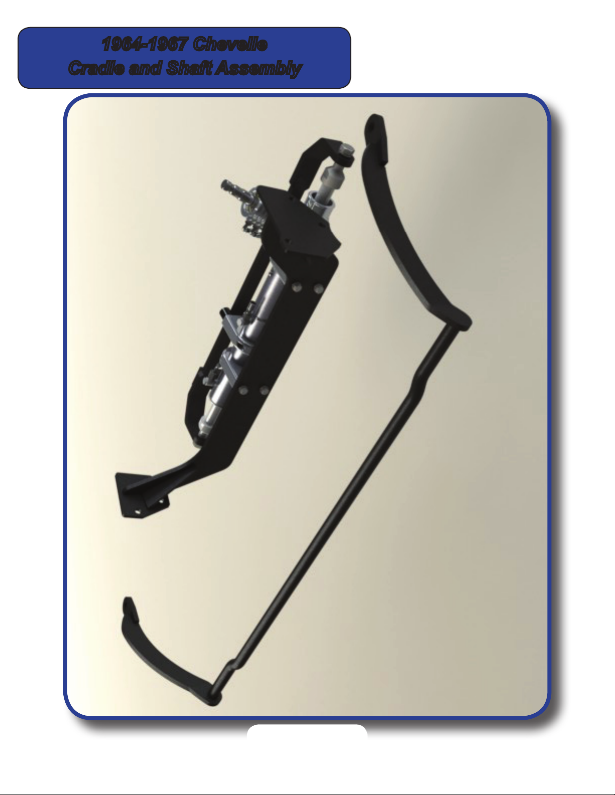
1964-1967 Chevelle
Cradle and Shaft Assembly
3
Flaming River Industries
1-800-648-8022
FRxxxx Rev.A
12/22/10
Page 5
Color Verication To Be Completed Before Disassembly
Before disconnecting the turn signal connector, verify the factory wiring colors and turn signal operation.
The use of a wiring diagram is recommended. This will be used when connecting the new Flaming River
Steering Column.
• Brake Light Switch
• Right Rear Turn Signal
• Left Rear Turn Signal
• Turn Signal Power
• Hazard Power
• Right Front Turn Signal
• Left Front Turn Signal
• Horn
Original System Removal
1) For safety, disconnect your battery.
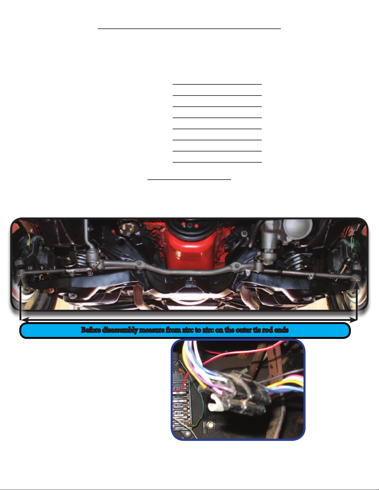
2) Before disassembly measure from zirc to zirc on the outer tie rod ends. Write this dimension down
for future reference.
Before disassembly measure from zirc to zirc on the outer tie rod ends
3) Disconnect the wiring at the steering
column under the dash.
4
Flaming River Industries
1-800-648-8022
FRxxxx Rev.A
12/22/10
Page 6

Original System Removal
4) Remove the bolts retaining the dash bezel, column dash mounting bracket and oor mounting
plate.
Dash Mounting Bracket
Dash Bezel
Floor Mounting Bracket
5) Remove the bolt that retains the rag joint
to the factory steering box. Spread the
ange and then slide the shaft off of the
steering box and remove the
column assembly from the car.
7) Remove the bolts that hold the steering
box to the frame, and then remove the box from
the car.
5
Flaming River Industries
1-800-648-8022
FRxxxx Rev.A
12/22/10
Page 7

Original System Removal
8) Remove the bolts that hold the idler
arm bracket to the frame, remove
the outer tie rod ends from
the spindle arms, then remove the
steering linkage from the car.
6
Flaming River Industries
1-800-648-8022
FRxxxx Rev.A
12/22/10
9) Remove the bolts that hold the
sway bar bracket to the frame and
the pin and remove the factory
sway bar from the vehicle.
Page 8

Flaming River Rack and Pinion Installation
1) Install the rack and pinion cradle by sliding it into place between the frame rails. Using the new
hardware, install the three (3) 7/16” bolts on the drivers side using the original holes from the
steering gear box. On the passenger side use the two (2) 3/8” bolts were the idler arm was
mounted. Tighten the 7/16” bolts and nuts to 50-65 ft lbs. and the 3/8” bolts and nuts to
40-45 ft. lbs..
Driver Side Mounting
Passenger Side Mounting
2) To install the Flaming River rack and travel bar system, position the rack into place, then install
and the rack to the cradle using the mounting brackets provided. Note: The locking set screw and
the mounting cap bolts can be loosened to adjust the pinion angle which will aid in u-joint
alignment.
Driver Side Mounting
Rack & Pinion Mounting
Brackets
7
Flaming River Industries
1-800-648-8022
FRxxxx Rev.A
12/22/10
Passenger Side Mounting
Page 9

Flaming River Rack and Pinion Installation
3) Install the OEM inner tie rod end into the Flaming River Travel Bar. Note: If using the original parts
some adjustment of the tie rod assembly may be required when connecting the to the spindle arm
and the travel bar.
OEM Inner Tie Rod End
4) To install the outer tie rod end into the
spindles you must load the front sus-
pension. Securely place jack stands un-
der the lower control arms and lowering
the car onto the jack stands. Make
sure that your wheels are centered,
then install the outer tie rod into the
spindle arms and tighten the
castle nuts to 30-40ft lbs. Make sure to
install the cotter pins through the castle
nut and tie rod end and bend the
tabs over.
Rack & Cradle Installed
In Car
Travel Bar
8
Flaming River Industries
1-800-648-8022
FRxxxx Rev.A
12/22/10
Page 10

Flaming River Rack and Pinion Installation
5) Install the new Flaming River sway bar
into the vehicle by using the factory
sway bar bushings and sway bar pins.
Tighten to factory torque specs.
Note:
The Flaming River Sway bar has been
designed to use the factory sway bar bushings
and pins. When installing the new sway bar
we recommend also replacing the bushings
(MOOG K8266) and sway bar pins (MOOG
K5227).
9
Flaming River Industries
1-800-648-8022
FRxxxx Rev.A
12/22/10
New Sway Bar
Page 11

Flaming River Tilt Column Installation
1) Install the new Flaming River
tilt column into the factory dash
mounting bracket..
OEM Column
Dash Mount
2) Slide new tilt column through the split ring
of the new aluminum oor mount and then
tighten the dash and oor mounts.
Split Ring
Column Tube
10
Flaming River Industries
1-800-648-8022
FRxxxx Rev.A
12/22/10
Page 12

Flaming River Tilt Column Installation
4) Replace the factory dash bezel using the
screws that were removed earlier.
Wiring Circuit
Brake Light Switch
Right Rear Turn Signal
Le Rear Turn Signal
Turn Signal Power
Hazard Power
Right Front Turn
Signal
Le Front Turn Signal
Horn
Connecting the Electric System
Pin Location
Vehicle Wiring
P
Reference Color
Verication from
column disassembly.
N
M
L
K
J
H
G
Column Wiring
White
Green
Yell ow
Purple
Brown
Blue
Light Blue
Black
11
Flaming River Industries
1-800-648-8022
FRxxxx Rev.A
12/22/10
Page 13

Universal Joint Installation
1) Install the support bearing and bracket,
with the bend facing towards the outside
of the car, onto the rear control arm
mounting bolt.
2) Using a 3/4” wooden dowel rod, mock
up the steering shaft to obtain the correct
shaft lengths and u-joint angle.
3) Once the correct shaft lengths are
obtained, install shafts and u-joints
snugging down each set screw so that it
leaves a mark in the shaft.
4) Remove the shafts and using a 1/4” drill
bit, dimple each mark left by the set
screws.
5) Re-install the shafts and u-joints using
a red thread locker on the set screw
threads. Tighten each set screw to
25 ft.. lbs. and then tighten all jam nuts
securely.
** We recommend that you regularly inspect the
u-joint set screws for tightness.**
Support Bearing
& Bracket
Dimple
12
Flaming River Industries
1-800-648-8022
FRxxxx Rev.A
12/22/10
Page 14

Power Steering Pump Bracket
Power Steering Lines (FR1610 Not included in Kit)
Included in the FR1610 kit is a ½” feed line that connects from the remote reservoir to the power steering pump. is is
attached using the 2 stainless steel hose clamps. e 3/8” Double Crimped Pressure Line will attach the pressure port of
the power steering pump and to the pressure side of your steering gear. AN ttings with o-rings are included to complete the installation. e single crimped 3/8” line is used for the return line from the steering gear to the reservoir. is
will attach to the steering gear to the reservoir using a AN Fitting and the ¼”NPT barbed tting with a stainless steel
hose clamp. Custom length hose kits can be ordered from Flaming River by providing a drawing with dimensions.
When cutting the stainless steel hose it is easier to use a chop saw or cut o wheel. Wrap the hose in black electrical tape
and cutting through the tape to help avoid fraying. You may need to use a side cutter to trim any frayed stainless steel
line. e lines can be installed to the 90 degree ttings loose until to ensure proper line routing. To tighten, hold the line
itself and tighten the ttings to 10-12 . lbs.
Note: Over crimping or kinking the line my cause damage
to the Teon liner and voids warranty.
Note: If you are not using
FR1610 P/S Line Kit you must
order FRM14x6AN & FRM16x6AN
AN Fittings for the rack.
13
Flaming River Industries
1-800-648-8022
FRxxxx Rev.A
12/22/10
Page 15

Power Steering Bleeding Procedure
1) Raise the front wheels off the ground and
support the vehicle on jack stands.
2) Turn the steering wheel to the left lock
and ll the reservoir and let the vehicle sit
for 2 minutes.
3) WITH THE ENGINE OFF - Rotate the
steering wheel lock to lock 20-25 times,
while rotating the wheel have someone
monitor the uid level and ll as
necessary.
4) Top off uid
5) WITH THE ENGINE RUNNING - Rotate
the steering wheel lock to lock 20-25
times, while rotating the wheel
have someone monitor the uid level and
ll as necessary.
6) Lower the vehicle
7) Top off uid
8) WITH THE ENGINE RUNNING - Rotate
the steering wheel lock to lock 20-25
times, while rotating the wheel
Install your power steering lines to the correct
pressure or return ports.
have someone monitor the uid level and
ll as necessary.
If using a stainless steel line kit, follow the instructions provided with your kit.
FR1610 Stainless Steel Line Kit is available Separately.
Note: If using the original power steering pump, you must rst ush the pump of any power steering uid.
Contaminated power steering uid may cause damage to the new rack and pinion.
Note: If the power steering uid is foamy, let the vehicle sit for 10 minutes and then repeat the bleeding procedure.
Note: Trapped air in the system will cause a milky appearance in the uid. Trapped air will also cause the uid level
to rise in the reservoir when the engine is not running.
14
Flaming River Industries
1-800-648-8022
FRxxxx Rev.A
12/22/10
Page 16

Flaming River Industries, Inc.
800 Poertner Dr. Berea, Ohio 44017
1-800-648-8022 • www.amingriver.com/chevelle
 Loading...