

Page 1
Page 2

INDEX
NOTE: Before beginning you must first measure the width of your front end from LEFT outer tie
rod end zirc to the RIGHT outer tie rod end zirc to determine the overall width of your front end.
Write dimension here for further reference
NOTE: Part number ES381RL 68-69 Camaro Outer Tie Rod Ends must be used
with this rack and pinion kit.
Parts Inventory PG 3
Original Column & Wheel Removal PG 4
Steering Box & Linkage Removal PG 4
Installation of New Flaming River Tilt Column PG 5
Electrical System Notes PG 6
Installation of Rack and Cradle PG 7
Universal Joint and Steering Shaft Installation PG 8
Steering Wheel Installation PG 9
Power Steering Bleeding Procedure PG 10
Power Steering Valve Diagram PG 10
Torque Specs PG 10
Note: For safety disconnect battery cables and ensure that vehicle is properly supported by jack
stands.
We recommend a professional alignment to set the proper alignment settings after system
installation.
We recommend that you always install new outer tie rod ends when installing this kit.
Warranty Disclaimer
Because of their intended usage, the manufacturer makes no warranties whatsoever express or
implied, oral or written, to purchasers of their products regarding performance, safety, fit
merchantability, or length of service. Purchasers are responsible for selection of proper goods and
must rely on there own skill or judgment that such goods are suitable for purchasers application.
Page 1 of 10
Modified on 18 Feb 08
JJ/RD/RP/BC
Page 3
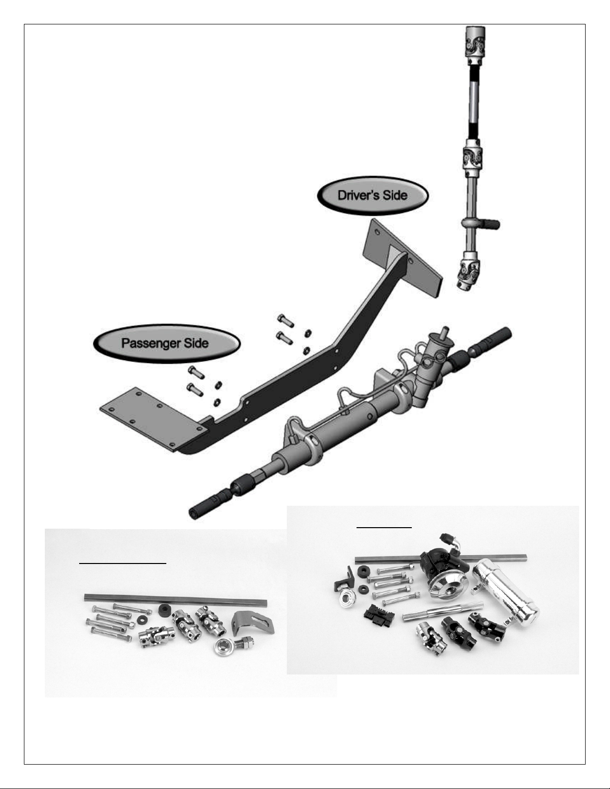
Manual System
Power Kit
Page 2 of 10
Modified on 18 Feb 08
JJ/RD/RP/BC
Page 4
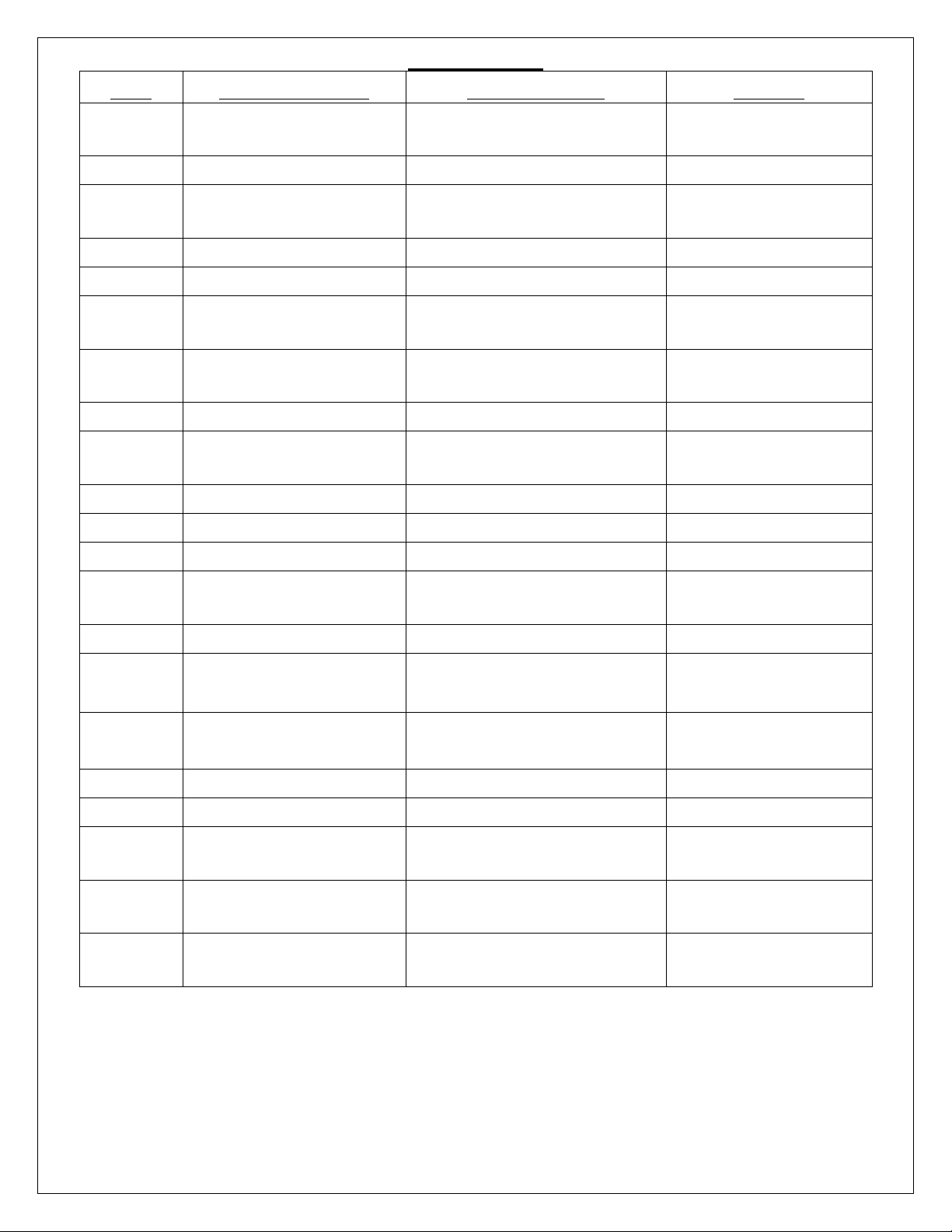
Parts Inventory
Qty Part Number Description Notes
1 BK10200
Support Bearing
Bracket Bent
1 FR1810 Support Bearing
3/8" -16 Grade 8 Bolt
3 Bolt-3/8-16x3.5
3.5" Long
3 Nut-3/8-16 Nylock Lock Nut 3/8-16
6 Wash-3/8" 3/8" Flat Washer
5/16-18 Bolt x 1 1/4"
6 5/16-18 x1.25
Long
Nylock Lock Nut 5/16-
6 Nut-5/16-18
18
6 Wash-5/16" 5/16" Flat Washers
Power Steering
1 FR1614
Reservoir
1 FR1850 18" DD Shaft
1 FR1920 3/4DD x 3/4DD U-Joint
1 FR1934 1 DD x 3/4DD U-Joint
Only with Power
Kit
1 FR1932
1 FR1924 9/16-26 x 3/4DD U-Joint Manual Kit Only
1 FR20005
1 FR20005SS
1 FR20114 Dash Mount
1 FR20118-1 Hazard Wiring Kit
1 FRPMPSB-V
1 FR305AYPW
1 FR305-AY
3/4DD x 17MMDD U-
Power Kit Only
Joint
30" x 2" Floor Shift
Paintable Kit Only
Paintable Tilt Column
30" x 2" Floor Shift
Polished Kit Only
Polished Tilt Column
Power Steering Pump
Power Kit Only
w/ V-Belt
Nova Power Rack
Power Kit Only
Assembly
Nova Manual Rack
Manual Kit Only
Assembly
Page 3 of 10
Modified on 18 Feb 08
JJ/RD/RP/BC
Page 5

Original Steering System Removal
1) Remove the pitman nut and remove the pitman arm from the steering box.
2) Remove the nuts that retain the outer tie rod ends and remove the tie rods from the spindle
arm.
3) If you have the power assist system you must also disconnect the slave cylinder from the
chassis and remove the mounting bracket.
4) Remove the bolts that retain the idler arm and remove the steering linkage from the car.(D)
5) Remove the two lower steering gear (C) mounting bolts and only loosen the third.
6) Disconnect all wiring connectors from column. (See page 5 for further information).
7) Remove the screws that hold the floor seal in place.
8) Using a steering wheel puller remove the steering wheel. (A)
9) Remove the two nuts that retain column mounting bracket under the dash.
(B-1)
10)Move the front driver’s seat to the rear most position and lower the column as far as possible.
11)While sitting in the seat, pull the column housing (B) towards you until it is completely off the
long pinion shaft.
12)Remove the final steering gear mounting bolt and remove the steering box. (C)
Page 4 of 10
Modified on 18 Feb 08
JJ/RD/RP/BC
Page 6

Installation of Flaming River Column
1) Slide the floor mount that is included in the kit over the column tube and then slide the original
floor seal and floor plate over the column tube.
2) Slide the column through the firewall so that the end of the column tube is about a ¼” past the
firewall.
3) Using the original under dash mount, mount the column to the dash. Only snug the mounting
bolts.
4) Set the turn signal arm at the 9 o’clock position; tighten down the mounting bolts to secure the
column.
5) Fasten the original floor seal to the firewall using the bolts removed earlier.
6) Next slide the column mounting bracket so that the mounting flange is flush against the floor
seal plate, and then snug the column mounting bracket to the column tube.
7) Fasten the column bracket to the floor seal using the hardware provided. NOTE: The new floor
mount assembly can be removed and painted.
Page 5 of 10
Modified on 18 Feb 08
JJ/RD/RP/BC
Page 7

Connecting Electrical System
Caution: Before disconnecting your original steering column wiring harness please verify
each wire color and function on the worksheet below. Some wire colors may vary from
year to year.
COLUMN WIRING
P-WHITE-BRAKELIGHT SWITCH
N-DK GREEN-RR TURN SIGNAL
M-YELLOW-LR TURN SIGNAL
L-PURPLE-TURN SIGNAL POWER
K-BROWN-HAZARD POWER
J-DK BLUE-RF TURN SIGNAL
H-LT BLUE-LF TURN SIGNAL
G-BLACK-HORN
Color Verification to be completed before disassembly
Brake Light Switch :
RR Turn Signal :
LR Turn Signal :
Turn Signal Power :
Hazard Power :
LF Turn Signal :
Horn :
Page 6 of 10
Modified on 18 Feb 08
JJ/RD/RP/BC
Page 8

Installation of the Flaming River Power or Manual Rack and Cradle
1) Center the rack by turning it all the way to the left. Next turn the rack all the way to the right,
counting the number of turns. Then go back half way.
2) Driver’s side: Hold up the rack mounting cradle where the steering gear box was originally
and snug the mounting hardware.
3) Passenger side: Mount the passenger side of the cradle using the original holes from the idler
arm and tighten the four 5/16” mounting bolts.
4) Driver’s side: Using a torque wrench tighten the mounting bolts to 50-65 ft lbs.
5) Passenger side: Using a 3/8” drill bit, drill through the remaining 2 holes on the cradle and
through the frame rail and install the final two 5/16” bolts. Tighten all the bolts to 30-40 ft lbs
Page 7 of 10
Modified on 18 Feb 08
JJ/RD/RP/BC
Page 9

Header Universal Joint System.
1) Install support-bearing mount onto the rear cradle bolt. (Diagram below). Note: The angle of
this mount is set for most applications. Some adjustment may be necessary for the correct
angle and u-joint alignment.
Support Bearing Bracket
2) We recommend the use of ¾” dowel rod to mock up the steering shaft to obtain the correct
length of the shafts.
3) Install your shaft kit and snug each set screw so that it will leave a mark in the shafts.
4) Remove shaft and dimple each setscrew mark using a ¼” drill bit. (As shown below.)
5) Re-install the shafts using red loc-tite thread locker on the set screw threads. Tighten each
setscrew to 25 ft. lbs. Tighten all lock nuts securely. We recommend that you inspect
setscrews periodically for tightness.
Page 8 of 10
Modified on 18 Feb 08
JJ/RD/RP/BC
Page 10

Steering Wheel Installation
1) Install horn contact kit into canceling cam tube and turn to lock.
2) Align steering wheel adapter so that the canceling cam hole is at approx the 11 O’clock
position and that one of the steering wheel mounting holes is at the 12 O’clock position.
3) To install the wheel adapter run the horn contact wire through the hole for the canceling cam
and place the adapter on to the splined column shaft.
4) Tighten the adapter-retaining nut until the adapter is approximately 1/16” away from the
column shroud.
Page 9 of 10
Modified on 18 Feb 08
JJ/RD/RP/BC
Page 11

Power Steering Bleeding Procedure
1) Fill the reservoir with high-quality power steering fluid and allow to sit for 2 minutes
2) Raise the front end of the vehicle so the wheels are just off the ground. Rotate wheels back and
forth at least 20 times. Have an assistant check and maintain fluid level while performing this
operation.
3) Start the engine and recheck fluid level. Add fluid if necessary.
4) With the engine running, rotate the steering wheel back and forth from lock-to-lock. Repeat several
times. Check fluid level and add fluid if necessary.
5) Lower the vehicle on the ground and with the engine running, repeat step 5. Check fluid level and
add if necessary
Torque Specs
Cradle to Frame Mounting Bolts
3/8” Mounting Bolts 40-45 ft lbs
5/16” Mounting Bolts 30-40 ft lbs
Outer Tie Rod Ends to Spindle 30-40 ft lbs
Universal Joint Set Screws 25 ft-lbs
Billet Rack Mounting Clamps 45-50 ft-lbs
Page 10 of 10
Modified on 18 Feb 08
JJ/RD/RP/BC
 Loading...