

Page 1
1960-1965 Comet
Page 2

Note: For safety disconnect battery cables and ensure that the vehicle is properly supported by jack
stands.
Before painting or powder coating of the cradle, we recommend that you pre-fit the entire system to ensure proper fitment for your application.
Inventory pg 2
Removal of Factory Steering pg 4 - 5
Installation of:
Flaming River Tilt Column pg 6
Electrical System Notes pg 7
Rack and Cradle pg 8
Universal Joint and Steering pg 9
Shaft Installation
Power Steering Pump Installation pg 10
Power Steering Bleeding Procedure pg 11
WARRANTY DISCLAIMER: Flaming River’s® Limited Warranty
Flaming River® warrants its products to be free from defects in material and workmanship for a
period of one (1) year after the date of purchase, except that: All steering columns are warranted for
a period of three (3) years from the date of purchase. The Big Switch (part number FR1005) is warranted for a period of three (3) years from the date of purchase, provided that it is not mounted with
a steel bracket and provided further that it is adequately protected from environmental conditions.
All electrical products other than the Big Switch are warranted for a period of ninety (90) days from
the date of purchase. Flaming River’s® warranty liability is limited to the replacement of defective
products. Flaming River® is not liable for any labor costs associated with any warranty claim, or for
any incidental or consequential damages. Improper installation, abuse, racing, and/or modification of
the products voids this warranty. No warranty of merchantability or fitness for a particular purpose is
made by Flaming River® with respect to any of its products. Warnings and Recommendations It is the
customer’s responsibility to determine the suitability of a given Flaming River® product for the customer’s uses. Likewise, it is the customer’s responsibility to install a Flaming River® product. Contact
the vehicle manufacturer whenever installing a switch to confirm the appropriateness of using such a
switch and the recommended placement of the switch on the vehicle. Use qualified chassis specialists
for the installation of all steering related components. Be aware that the installation of certain Flaming River® products may adversely impact a manufacturer’s warranty with respect to certain vehicles
and other manufactured goods. Flaming River will repair or replace any product found to be defective
in material or workmanship. Improper installation, abuse, racing and/or modification VOID WARRANTY.
Flaming River® is not responsible for any labor costs associated with any warranty.
Page 3
Part No. DescriPtioN Qty Notes
100954 Mounting Hardware Kit 1
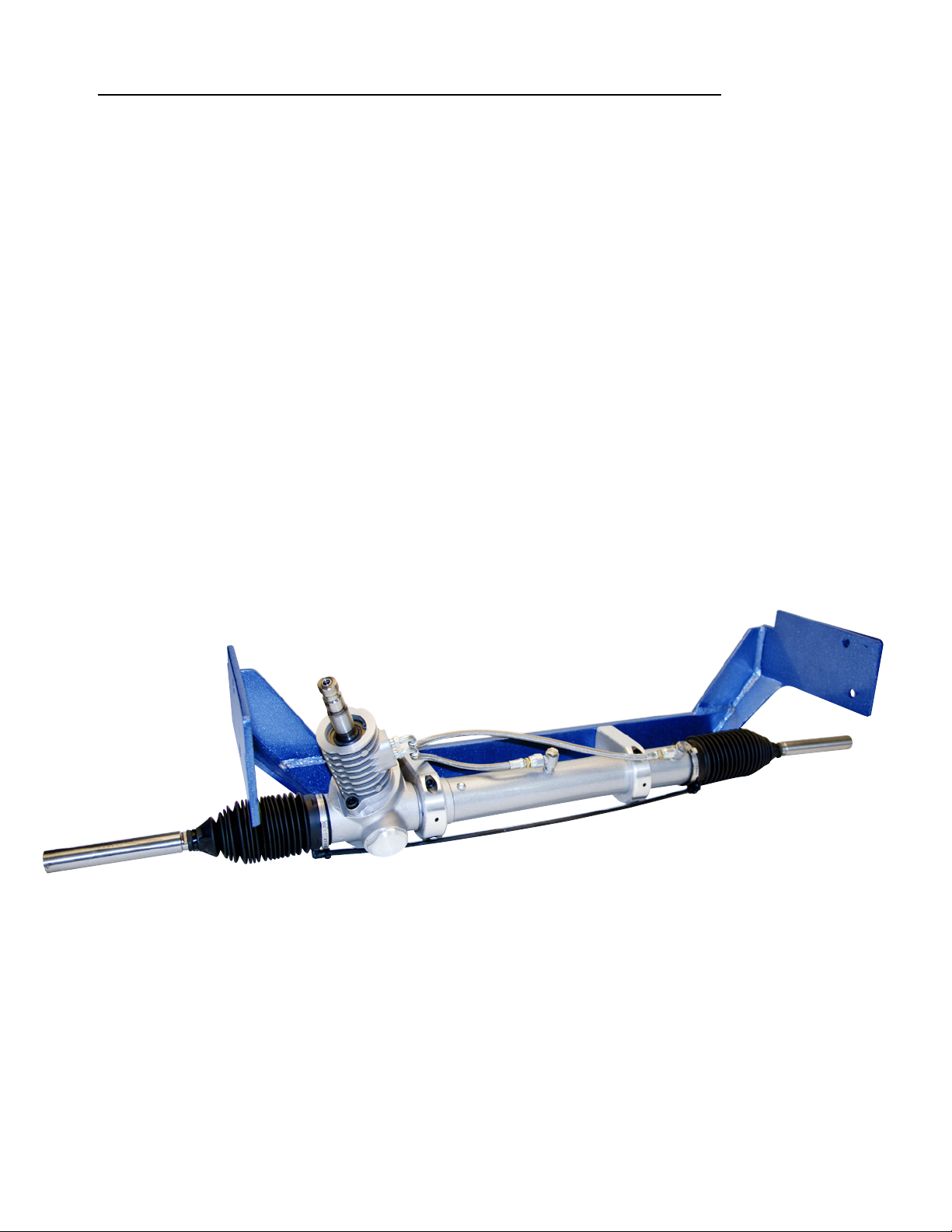
100956 Power Rack & Pinion Cradle Assembly 1
FR1614 Remote Power Steering Fluid Reservoir 1
FR1934 1”DD x 3/4”DD Universal Joint 1
FR1969 3/4”DD x FR Power Universal Joint 1
FR20010RK Billet Aluminum Shift Linkage 1 Column Shift Kit Only
FR20059 Adjustable Shift Arm 1 Column Shift Kit Only
FR20097 Aluminum Floor Mount 1
FR20118-1 Wiring Connector w/Hazards 1
FR21017 Tilt Column Shift Steering Column 1 Column Shift Kit Only
FRXXXXX Tilt Floor Shift Steering Column 1 Floor Shift kit Only
FRHRN2 Horn Relay 1
FRMBPW1 Power Steering Pump Bracket 1
FRPMPSB-V Power Steering Pump w/ V-Belt Pulley 1
2
Flaming River Industries
1-800-648-8022
081511
Page 4
3
Flaming River Industries
1-800-648-8022
081511
Page 5

Original System Removal
1. If your vehicle has a column shift style
steering column, disconnect the
transmission shift linkage from the
steering column.
2. Remove the horn button by pushing down
on the horn button and turning counter
clockwise. Next remove the steering
wheel retaining nut and then using a
wheel puller remove the steering wheel
from column.
3. Remove the two nuts from the column
support bracket from under the dash.
Next unplug the electrical connector that
connects the steering column to the
vehicle harness.
Flaming River Industries
1-800-648-8022
4. Remove the upper alignment bushing
that is located at the center of the turn
signal switch. Next remove the column
tube by sliding it off of the column shaft.
4
081511
Page 6

Original System Removal
Pitman Arm
Idler Arm
Outer Tie Rod Ends
5. Remove the pitman arm from the steering box using a pitman arm puller.
Note: If the vehicle is equipped with power steering remove any power steering lines connected to
valve and drain the system.
6. Remove the two (2) bolts that retain the idler arm to chassis.
7. Remove the cotter pins and the castle nuts from the outer tie rod ends, using a pickle fork remove
the tie rod ends from the spindle arms and then remove the steering linkage from the vehicle.
8. Remove the three (3) bolts that hold the
steering to chassis and remove the
steering box from the car.
5
Flaming River Industries
1-800-648-8022
081511
Page 7

Installation of Flaming River Tilt Column
A B
1. Slide new swivel fl oor mount over the column tube (Picture A) so the swivel portion of the fl oor
mount is at the end of he column tube (Picture B). Next place the column through the fi rewall and
loosley mount the fl oor mount to hold the column in place.
2. Place the rubber spacer into the factory
under dash mount and trim away excess.
Next, making sure the column is straight, fi t
the under dash mount to the new Flaming
River steering column and then mount the
steering column in the factory original
position.
New Flaming River steering
column installed.
6
Flaming River Industries
1-800-648-8022
081511
Page 8

Connecting the Electrical System
Function FR Column Location Vehicle Wiring
Horn
Lt Front Turn Signal
Rt Front Turn Signal
Hazard
Turn Signal - Power
Lt Rear Turn Signal
Rt Rear Turn Signal
Brake Light
Note: The hazard power wire goes to a 12v power source from the vehicle’s fuse panel. This feature will
add 4-Way Emergency flasher to the car.
Column Plug
Black
Light Blue
Blue
Brown
Purple
Yellow
Green
White
G
H
J
K
L
M
N
P
Brown (Horn Relay)
Green/White
White/Black
See Note
Blue
Green/Orange
Orange/Blue
Green
Female Wiring Connector
Horn Relay
1. Connect the Yellow and Blue wires on the horn relay to the Yellow wire on the vehicle harness.
2. The Red wire on the horn relay connects to the Yellow wire with a stripe on the vehicle harness.
3. The Brown wire on the horn relay connects to the Black wire on the steering column harness
terminal G.
Note: The Black wire on the horn relay is not used.
7
Flaming River Industries
1-800-648-8022
081511
Page 9

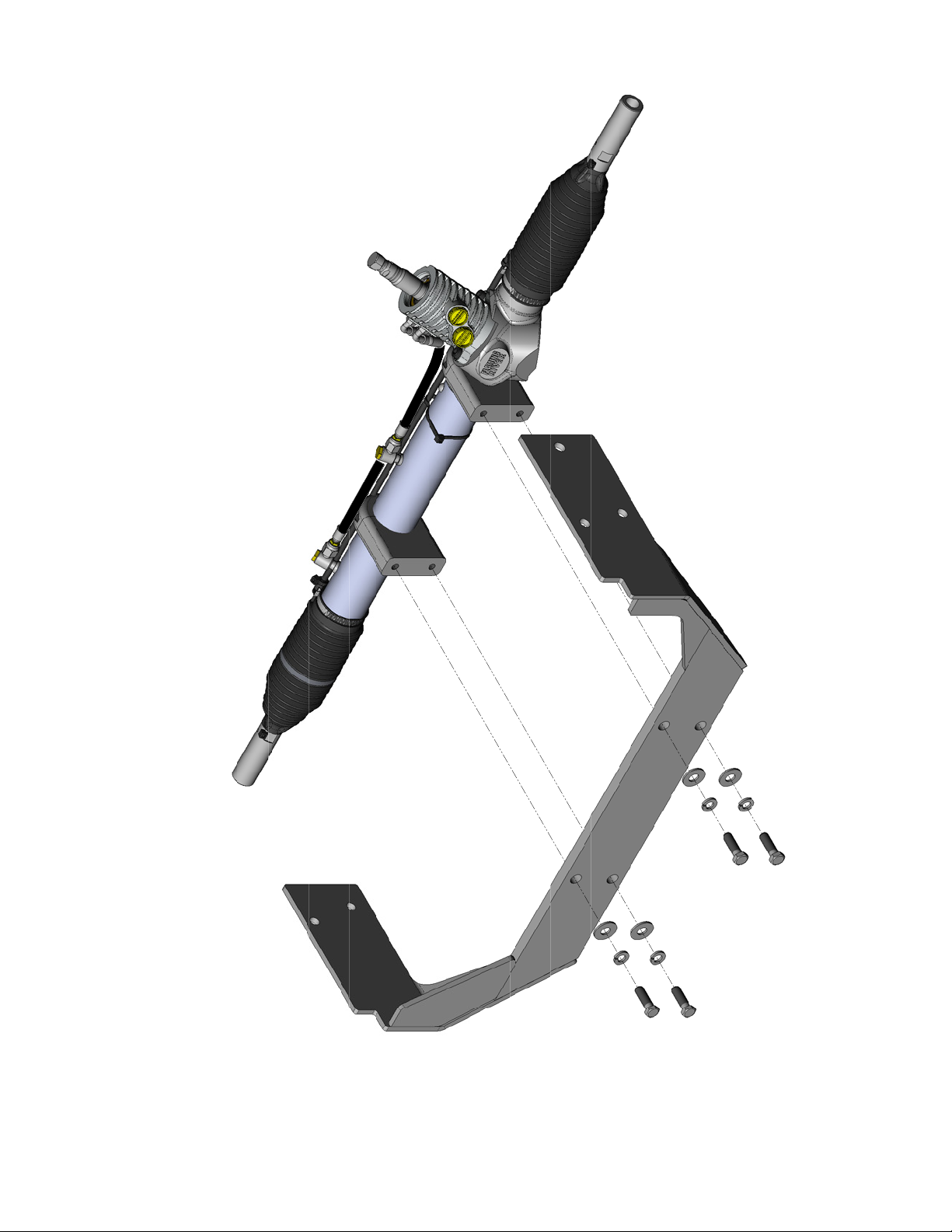
Installation of Flaming River Rack & Cradle System
The rack mounting cradle is only shown
here to show the mounting bolts.
Driver Side Passenger Side
1. Install the rack and pinion cradle by sliding it into place between the frame rails. Using the
new hardware, install the three (3) 7/16” bolts on the drivers side using the original holes from the
steering gear box. On the passenger side use the two (2) 3/8” bolts were the idler arm was
mounted. Tighten the 7/16” bolts and nuts to 50-65 ft lbs. and the 3/8” bolts and nuts to
40-45 ft lbs..
Rack & Cradle Shown Installed.
8
Flaming River Industries
1-800-648-8022
081511
Page 10

Installation of Universal Joints & Shafting
View from Top
View from bottom
1. Using a 3/4” wooden dowel rod, mock
up the steering shaft to obtain the correct
shaft lengths and u-joint angle.
2. Once the correct shaft lengths are obtained,
install shafts and u-joints snugging down each
set screw so that it leaves a mark in the shaft.
3. Remove the shafts and using a 1/4” drill
bit, dimple each mark left by the set screws.
4. Re-install the shafts and u-joints using a red
thread locker on the set screw threads. Tighten
each set screw to 25 ft lbs. and then tighten all
jam nuts securely.
** We recommend that you regulary inspect the
u-joint set screws for tightness.**
9
Flaming River Industries
1-800-648-8022
081511
Page 11

Water Pump
Power Steering
Pump Bracket
Installation of Power Steering Pump
Power Steering
Fluid Reservior
Power Steering Pump
1. Install the power steering pump bracket to the water pump as shown in the picture.
2. Mount the power steering pump to the bracket. Only snug the mounting bolts, the mounting bolts will
be tightened once the belt is installed and the pulley is adjusted.
3. Install the power steering fl uid reservior, the reservior must be mounted higher than the pump for
correct fl uid fl ow to the pump.
Flaming River Synthetic Power Steering Fluid
Formulated for High Performance Steering Systems! This
newly developed line of Synthetic Power Steering Fluid
is a natural addition to Flaming River’s Power Rack and
Pinions and Power Steering Accessory product lines.
Available in a 1 quart bottle, this Power Steering Fluid
reduces operating temperatures and fl uid expansion,
resists foaming, and also increases the life of power
steering systems by reducing internal wear and tear.
Flaming River’s Synthetic Power Steering Fluid is recommended for all power steering applications. Simply
purge the vehicle of its current power steering fl uid and
replace with Flaming River’s unique blend that easily
mixes with any trace amounts of other steering fl uid left
behind.
FR41001 – Flaming River Synthetic Power Steering Fluid
10
Flaming River Industries
1-800-648-8022
081511
Page 12

Power Steering Bleeding Procedure
1. Raise the front wheels off the ground
and support the vehicle on jack stands.
2. Turn the steering wheel to the left lock
and fi ll the reservoir and let the vehicle sit
for 2 minutes.
3. WITH THE ENGINE OFF - Rotate the
steering wheel lock to lock 20-25 times,
while rotating the wheel have someone
monitor the fl uid level and fi ll as necessary.
4. Top off fl uid
5. WITH THE ENGINE RUNNING - Rotate
the steering wheel lock to lock 20-25
times, while rotating the wheel have
someone monitor the fl uid level and fi ll as
necessary.
6. Lower the vehicle
7. Top off fl uid
8. WITH THE ENGINE RUNNING - Rotate
the steering wheel lock to lock 20-25
times, while rotating the wheel have
someone monitor the fl uid level and fi ll as
necessary.
Install your power steering lines to the
correct pressure or return ports.
If using a stainless steel line kit, follow the instructions provided with
your kit.
FR1610 Stainless Steel Line Kit is available Seperatley.
Note: If using the original power steering pump, you must fi rst fl ush the pump of any power
steering fl uid. Contaminated power steering fl uid may cause damage to the new rack and pinion.
Note: If the power steering fl uid is foamy, let the vehicle sit for 10 minutes and then repeat the
bleeding procedure.
Note: Trapped air in the system will cause a milky appearance in the fl uid. Trapped air will also cause
the fl uid level to rise in the reservoir when the engine is not running.
11
Flaming River Industries
1-800-648-8022
081511
 Loading...