

Flamerite Fires OMNIGLIDE Glazer Series, OMNIGLIDE Glazer 900 Installation Manual

Green and yellow:
EARTH
Blue:
NEUTRAL
Red:
LIVE
Glazer Fires Featuring
This product is only suitable for well insulated spaces or occasional use
Installation & Precautions
Warning: Due to the weight of the fireplace, you should be mindful that during the installation there is a high risk of falling
forwards, we recommend two persons throughout fitting.
Carefully remove the fire from the packaging, checking that neither the heater nor the power cable has been damaged during transport. Do not
operate the fire if either is damaged. Please bear in mind the weight of the fire before removal from the packaging and installation. Consider if
help is required. Any alteration to the power cable should only be done by a qualified electrician and to the Flamerite Fires guidelines stated
below. Your fire is guaranteed for one year from the date of purchase. In the unlikely event of a breakdown you have access to our customer
services team, simply call 01543 251122 during office hours, 9am – 5pm or e-mail on info@flameritefires.com
that is packed at the side of the fire.
INSTALLATION
1. Where a chimney is not blocked off completely it will cause the heater to cut out during use. ONLY if installing into a
chimney where you are not sure that you have cut off 100% of the drawn air then we recommend covering the slots in
the rear and at either side.
Automatic safety cut out: The heater is fitted with an automatic cut out to prevent any damage due to overheating. The element will continually
and automatically cut out if the airflow is obstructed. Never cover the air outlets. To reset, switch the fire off, disconnect from the mains supply,
remove the cause of the overheating, check the micro switches and allow to cool for a suitable period then switch the fire back on. Caution: In
order to avoid a hazard due to inadvertent resetting of the thermal cut out, the appliance must not be supplied through an external switching
device, such as a timer, or connected to circuit regularly switched on and off by a utility.
2. Insert the plug tightly into its IEC connector underneath the fire if not already done so. If the removal of the plug is absolutely
necessary for installation, cut off in an area within 100mm only of the plug itself. Any further will affect your warranty.
Electrical connections. Your appliance comes fitted with a plug that incorporates a 13A fuse. The replacement fuses must be 13A and ASTA
approved. If the fuse cover is lost the plug must not be used until a replacement cover, of the same colour, is obtained from an electrical retailer.
The appliance is fitted with a moulded plug if it is necessary cut off the plug, for any reason, it must be discarded immediately with the fuse
removed. Under no circumstances should any attempt be made to reuse the plug, do not insert into any 13A socket as this could cause a hazard. If
the mains cable is damaged it must be replaced by the manufacturer or an authorised technical service centre.
WARNING THIS APPLIANCE MUST BE EARTHED
IMPORTANT
The wires in the mains lead are coloured in accordance with the following code.
The accessories are found in a box
As the colours of the wires in the mains lead of this appliance may not correspond with the colour markings in your plug proceed as follows: -
• The wire which is coloured green and yellow must be connected to the terminal in the plug which is marked with the letter E, or
coloured green or coloured green and yellow, or marked with the earth symbol
• The wire which is coloured blue must be connected to the terminal in the plug which is marked with the letter N, or coloured
black.
• The wire which is coloured brown must be connected to the terminal in the plug which is marked with the letter L, or coloured
red.
Fitting options: The Glazer fire can be fitted as part of a freestanding fireplace or wall mounted. If freestanding the fire can simply be sat on its
base as long as it is secured into place as part of the overall fireplace. If fitting into a Flamerite modular suite separate instructions will be provided,
however if the suite is wall mounted the below instructions will need to be followed first.
Wall mounting fixing kit: 7 x M10 x 50mm Rawl plugs. 7 x 60mm screws. 2 x M6 x 25mm bolts. 2 x M6 washers. 4 x 13mm screws (fitted)
1 | Page
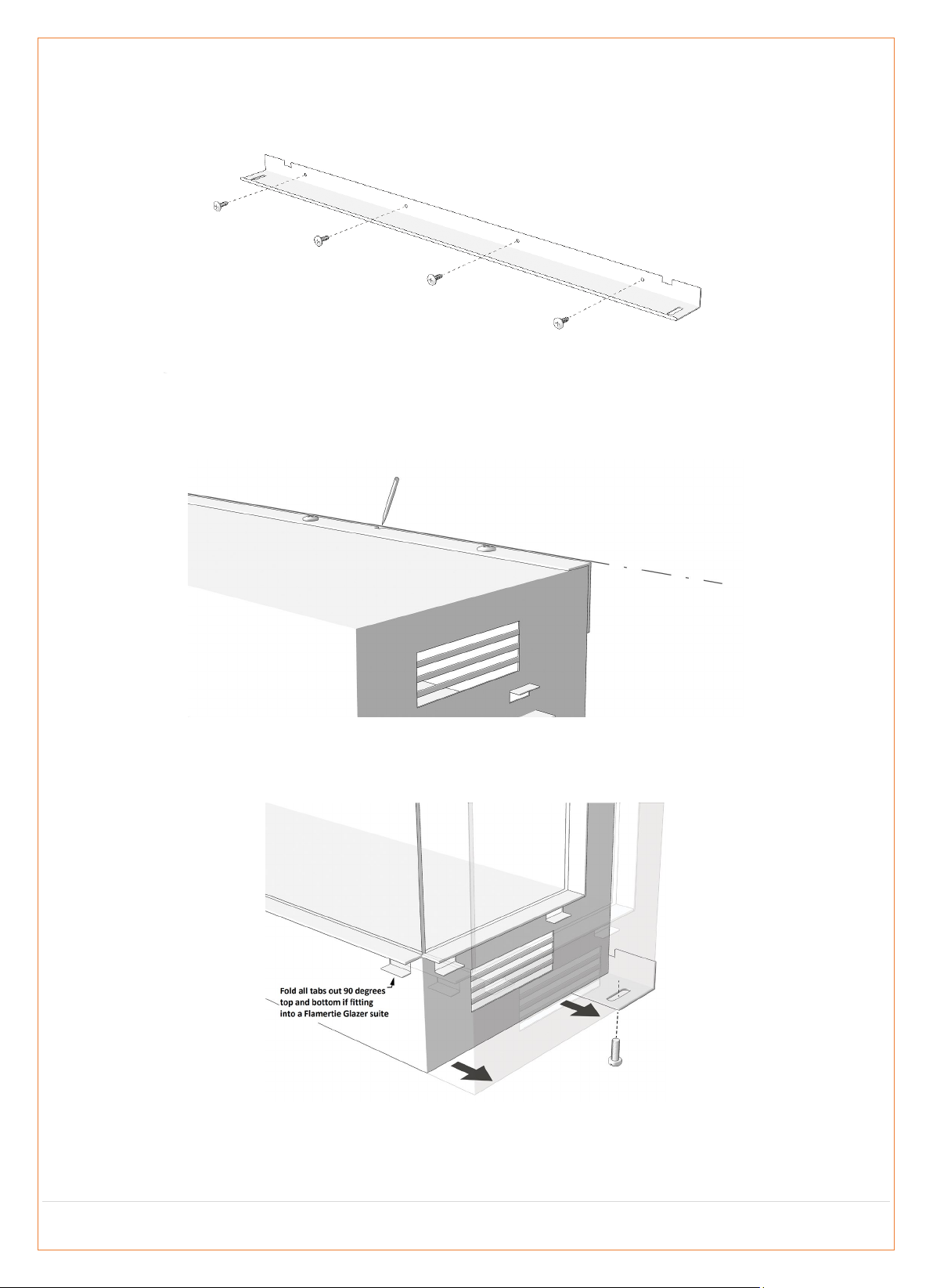
Using as Wall Mounted: The fire comes with two hanging rails, top and bottom to enable fixing the Glazer to the wall. Although your preference,
we recommend no lower than 400mm from the bottom of the fire opening to the floor so the bottom bracket should be fixed 290mm or above
from the floor. Mark the holes, drill and fit the rawl plugs using an M10 bit. Using the 60mm screws fix the bracket to the wall.
Position the fire on top of the bottom bracket making sure the corner bolts fit through the slots either side and can screw into the underside of the
fire. With the top bracket attached to the fire, mark across its length and into the slots above each hole on the back edge. Remove the fire,
remove the top bracket and 13mm screws from the fire and mark the holes on the wall, drill and fit the rawl plugs using an M10 bit. Using the
60mm screws fix the bracket to the wall.
Slide the fire into the channel created by the top and bottom brackets. Screw the top bracket back onto the fire with the 13mm self-tappers and
bolt each corner of the bottom bracket threw the slots either side into the fire using the M6 bolts and washer supplied. At this point you will be
able to level the fire accordingly at the base by loosening and tightening the bottom bolts.
Fitting the Glass:
A: Push the side glass back towards the rear of the case
B & C: You will notice there is a long gap on the underside of the opening 10mm in width that runs along and in front of the heater grills. At an
angle of approximately 45 degrees push the glass up into this void making sure the bottom of the glass clears the lower edge of the opening. Tilt
the glass back into the fire and carefully lower into the large channel that runs across the opening avoiding the dampers.
2 | Page
 Loading...