

Page 1 of 4
Flamerite Omni 2 Electric Floor Standing Fire Suite
INSTALLATION OF THE FIRE
Where a chimney is not blocked off completely it will cause the heater to cut out during use. If you are not sure that you have cut off the draw
100% from the chimney, we recommend covering the five banks of slots in the rear of the case and each bank at the top either side.
Electrical connections
Your appliance comes fitted with a plug that incorporates a 13A fuse. The replacement fuses must be 13A and ASTA approved. If the fuse cover is
lost the plug must not be used until a replacement cover, of the same colour, is obtained from an electrical retailer.
The appliance is fitted with a moulded plug, if it is necessary to cut off the plug for any reason, it must be discarded immediately with the
fuse removed. Under no circumstances should any attempt be made to reuse the plug, do not insert into any 13A socket as this could cause
a hazard. If the mains cable is damaged it must be replaced by the manufacturer or an authorised technical service centre.
WARNING THIS APPLIANCE MUST BE EARTHED
IMPORTANT
The wires in the mains lead are coloured in accordance with the following code.
Green and yellow:
EARTH
Blue:
NEUTRAL
Red:
LIVE
As the colours of the wires in the mains lead of this appliance may not correspond with the colour markings in your plug proceed as follows: -
The wire which is coloured green and yellow must be connected to the terminal in the plug which is marked with the letter E, or
coloured green or coloured green and yellow, or marked with the earth symbol
The wire which is coloured blue must be connected to the terminal in the plug which is marked with the letter N, or coloured
black.
The wire which is coloured brown must be connected to the terminal in the plug which is marked with the letter L, or coloured
red.
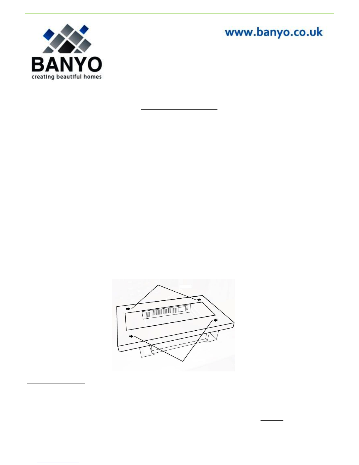
The Fire Front: is held on by four keyhole slot brackets, the corresponding screws are attached to the case. Lift the front to remove or replace it
back onto the fire. Fig.1
Fig.1
Using as a Hole in the Wall:
The inset dimensions for Hole in the Wall: depth 16cm, height 50cm and width 90.5cm. To prevent the fire from being pulled over it must be
secured into place. The height at which you may wish to fix the fire to the wall is up to you, though we recommend anywhere from 40-60cm from
the floor to the bottom of the fire. Four counter sunk holes will be visible at each corner, two on each side of the outer return. Place the fire into
the hole, mark off where the fixing holes are to be drilled. Remove fire and drill the holes. When this is done push the rawl plugs into the drilled
holes, lift and secure the fire into place. The front may be reapplied by lining up the keyhole slot brackets with their corresponding screws on the
fire and pushing it down. The screws may need to be adjusted to remove any slack and allow for a tight fit. *See fuel effect before fitting the
glass.
Page 2 of 4
Using as a Hang on the Wall.
The height at which you may wish to fix the fire to the wall is up to you, though we recommend anywhere from 40-60cm from the floor to the
bottom of the fire. The rail should be fixed to the wall with the hooks facing upward and outward. Once the rail has been fixed in place, lift and
hook the fire onto the rail. Next at the back of the case (bottom/centre) is a fold out tag. Fold this down to expose it under the fire when it is hung
in place. Mark off through the hole, remove fire, drill and fit rawl plug. Hang the fire back on the wall and secure in place using the screw provide.
The front may be reapplied by lining up the keyhole slot brackets with their corresponding screws on the fire and pushing it down. The screws may
need to be adjusted to remove any slack and allow for a tight fit. Finally slide the 6mm MDF board under the spacer on the back of the fire all the
way to the rear. *See fuel effect before fitting the glass.
Important: The fire must be positioned so that the plug socket is accessible once the fire has been installed. In the unlikely event of breakdown
access must be allowed for so that the fire may be serviced (DO NOT SEAL). This will involve the fire being removed from the wall in order to
gain access to the rear. The mains cable must therefore be long enough to allow this. If the removal of the plug is absolutely necessary for
installation, cut off in an area within 100mm only of the plug itself. Any further will affect your warranty. Where an inset fire is being used in
an existing chimney, it is important that the chimney is blocked off to prevent airflow problems with the fire.
*Fuel effect
White & Glass Pebbles: Once the fire has been installed in the correct position unpack the pebbles from the accessory box and arrange on
the orange fuel bed in a random formation. Use the long clear right angled shelf to prevent any spill of the pebbles into the glass channel
on the front Fig.2. The glass may now be fitted Fig.3.
Fig.2
Log & Embers: Once the fire has been installed in the correct position unpack the fuel effect from the accessory box. Place each piece as in
the picture below. Do not overlap the front shelf Fig.2. The glass may now be fitted Fig.3.
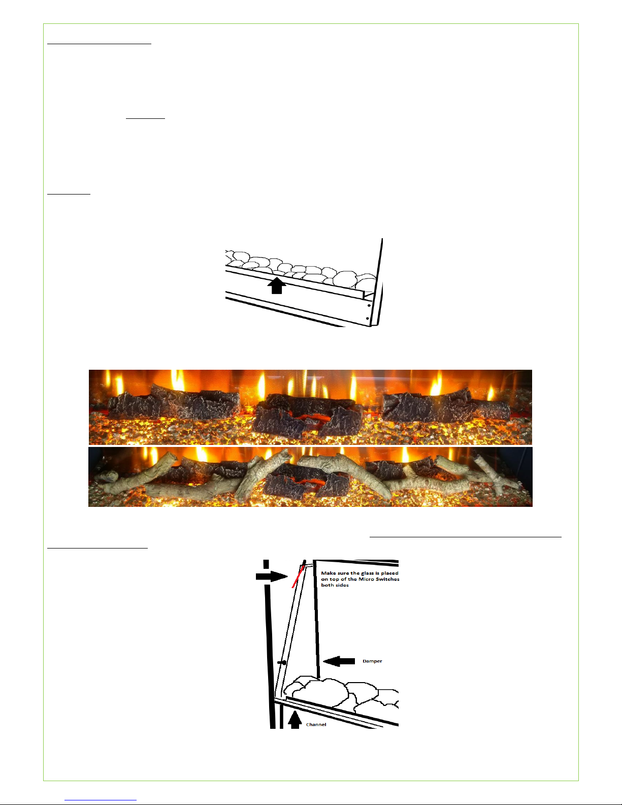
Fitting the Glass: Fig.3. Whist holding at the bottom of the glass, place the top edge through the fire opening up both sides of the interior making
sure you start after the dampers and lift over the micro switches on both sides at the top. IMPORTANT: The glass must be placed on top of the
metal arm and NOT under! Allow the bottom edge of the glass to sit into the channel in front of the fuel bed. To remove the glass, in the open fully
tilted position hold from the very top, pull out of the channel and carefully remove through the opening, bottom edge first.
Fig.3.

Page 3 of 4
OPERATING THE FIRE
Controls: The fire can be operated either by manual or remote control. There is a main on/off switch top right of the fire, this is marked
with I/O and will need to be switched to I (standby) to operate the fire. In the O position (off) you will be unable to operate the fire.
Fig 4 Fig 5
1. To turn the fire on (Fig 4 and Fig 5), simply press and release the FIRE ON button on the remote or manual keypad.
2. To set the inner flame & fuel effect to your desired brightness press + or - buttons marked DIMMER1 or 1.
3. To set the outer flame & fuel effect to your desired brightness press + or - buttons marked DIMMER2 or 2.
4. To activate or deactivate the outer flame & fuel flicker function press and release button Flicker. The flicker function will always
deactivate once the fire is turned off.
5. *For heating the fire must be switched on and the glass tilted to its back position by pushing the handle in the top right of the screen
briefly inwards. To give 1kw of heat, press then release the button marked ON/OFF HEAT O/I. To increase the temperature to 2kw
press then release button marked HI/LO or I/II. You may alternate from 1kw to 2kw by pressing HI/LO I/II at anytime. To turn
the heater off, press then release the button marked ON/OFF O/I. The heater will always start in the lower setting
6. To turn the fire to standby press then release the button marked FIRE OFF .
7. To turn the off depress the main on/off switch to the O position
Setting time on remote control: On the remote control turn the fire off so the only symbol . Hold down Flicker & lower 1 (-)
buttons at the same time for three seconds and the hour will flash. Use 2 + or – buttons to set hour noting that there is an AM /PM
suffix. Press Flicker again to move on to minutes and again use 2 + or – buttons. Finally press Flicker again to set the time.
*Important: Do not open and close the glass repeatedly while the heater is on or the cut out will activate.
Automatic safety cut out: The heater is fitted with an automatic cut out to prevent any damage due to overheating. The element
will continually and automatically cut out if the airflow is obstructed. Never cover the air inlets or outlets. To reset, switch the fire
off, disconnect from the mains supply, remove the cause of overheating and allow to cool for a suitable period then switch the fire
back on. Caution: In order to avoid a hazard due to inadvertent resetting of the thermal cut out, the appliance must not be supplied
through an external switching device, such as a timer, or connected to circuit regularly switched on and off by a utility.
Areas around the fire will become hot when activated. We strongly recommend small children be kept away from having any direct
contact with the appliance by means of fitting a fireguard. This appliance is not intended for use by persons (or children) with reduced
physical sensory or mental capabilities or lack of experience or knowledge unless they have been given supervision or instruction
concerning the use of the appliance by the person responsible for their safety. Children should be supervised to ensure they do not
play with this appliance.

Page 4 of 4
MAINTENANCE
Before any maintenance/cleaning is undertaken, always disconnect the fire from the mains power supply.
Replacing Lamps (Dimmable 240V 5W 3000k E14 LED lamps): Replacements are available from Flamerite Fires info@flameritefires.com
Allow a suitable time for the lamps to cool then remove the glass & fuel effect (see Installation). Remove the two screws from either side of the
fuel bed and lift out of place. Remove and replace the lamps, fuel bed, fuel effect and glass. Please note that replacement Lamps are only covered
from purchase by a 2 year warranty
Changing or matching remote frequency: If you receive a replacement remote in cases of loss/damage or you need to change frequency you must
follow a simple procedure to match the remote with the appliance.
1. Make sure the fire is plugged in at the mains, turned to standby (I on main on/off switch) and the LED on the manual keypad is lit Fig. 5.
2. On the manual keypad Fig. 5 on the fire press and hold the heater on & heater Hi/Low buttons together (centre buttons) for 5 seconds and the
LED will flash.
3. Press the button on the remote control Fig. 4. The fire will turn on & off twice.
The procedure is now complete and the fire is once again ready for use. (If there is no illumination, turn off main on/off switch and leave for one
minute to reset software).
Changing battery in the remote
Your remote has two batteries a CR2032 Lithium Battery and an alkaline MN21 12 Volt battery, replacements are available from Flamerite Fires
stockists, most electrical or photographic stores. Ensure battery is disposed of safely. Do not dispose of in fire, do not swallow and keep away
from children.
Cleaning
The fire can be cleaned with a soft damp cloth and none abrasive glass cleaner.
Warnings
Do not open and close the glass repeatedly while the heater is on or the cut out will activate.
Do not use the fire in the vicinity of a bath shower or swimming pool.
Never use the fire to dry laundry.
Never install the fire directly underneath a fixed main socket.
Never cover the appliance during the operation of the fire.
The use of an extension lead is not recommended.
Particular caution should be applied to ensure that children do not play with the fuel effects.
As with any electrical appliance whilst the instructions aim to cover as many eventualities as possible, caution and common
sense should be applied when operating your appliance, particularly in the vicinity of small children.
Problem solving
No power to the fire: Check the wall socket, plug, fuse and lamps.
No illumination: Make sure fire is turned on. Check heater is working, if so check lamps.
Illumination but heater blowing cold: The safety cut out may have operated. Check for obstruction around the heater. If
installed into a chimney or cavity wall is 100% of drawn air blocked off from the fire.
Noise when illuminated: Due to moving parts, the electric fire will make a noise.
Noise from the heater when in use: The sound of rushing air is normal.
 Loading...