

Flame Energy ULC-S627, UL-1482, NXT-I, XVR-I, XVR-I SE User Manual
...
FLAME E.P.A. WOOD STOVE MANUAL
US ENVIRONMENTAL PROTECTION
AGENCY PHASE II CERTIFIED
WOOD STOVE
Verified and/or tested following
ULC S627 and UL 1482 Standards by:
STOVE BUILDER INTERNATIONAL INC..
250, rue de Copenhague, Saint-Augustin-de-Desmaures (Quebec) G3A 2H3
Tel: ( 418 ) 878-3040
Fax: ( 418 ) 878-3001
This manual is available for free download on the manufac turer’s web site. It is a copyrighted
document. Re-sale is strictly prohibited. The manufacturer may update this manual from time
to time and cannot be responsible for problems, injuries, or damages arising out of the use of
information contained in any manual obtained from unauthorized sources.
READ AND KEEP THIS MANUAL FOR REFERENCE
Printed in Canada 45158A
16-11-2011

INTRODUCTION
Stove Builder International, one of the most important wood stove and fireplace manufacturers in
North America, congratulates you on your purchase and wishes to help you get maximum
satisfaction from your wood stove. In the pages that follow, we will give you advice on wood
heating and controlled combustion as well as technical specifications regarding installation,
operation and maintenance of the model you have chosen.
The instructions pertaining to the installation of your wood stove in North America comply with
ULC-S627 and UL-1482 standards.
We recommend that our woodburning hearth products be installed and serviced by professionals who
are certified in the United States by NFI (National Fireplace Institute®) or in Canada by WETT
(Wood Energy Technical Training) or in Quebec by APC (Association des Professionnels du
Chauffage).
Read this entire manual before you install and use your new stove. If this stove is not properly
installed, a house fire may result. To reduce the risk of fire, follow the installation instructions.
Failure to follow instructions may result in property damage, bodily injury, or even death.
Consult your municipal building department or fire officials about restrictions and installatio n
requirements in your area and the need to obtain a permit.
KEEP THIS INSTRUCTIONS MANUAL FOR FUTURE REFERENCE.
CAUTIONS:
THE INFORMATION GIVEN ON THE CERTIFICATION LABEL AFFIXED TO THE APPLIANCE ALWAYS
OVERRIDES THE INFORMATION PUBLISHED, IN ANY OTHER MEDIA (OWNER’S MANUAL, CATALOGUES,
FLYERS, MAGAZINES AND/OR WEB SITES).
HOT WHILE IN OPERATION. KEEP CHILDREN, CLOTHING AND FURNITURE AWAY. CONTACT MAY
CAUSE SKIN BURNS.
DO NOT USE CHEMICALS OR FLUIDS TO IGNITE THE FIRE.
DO NOT LEAVE THE STOVE UNATTENDED WHEN THE DOOR IS SLIGHTLY OPENED DURING IGNITION.
DO NOT BURN WASTE, FLAMMABLE FLUID SUCH AS GASOLINE, NAPHTHA, OR MOTOR OIL.
DO NOT CONNECT TO ANY AIR DISTRIBUTION DUCT OR SYSTEM.
ALWAYS CLOSE THE DOOR AFTER IGNITION.
2

TABLE OF CONTENTS
SECTION 1.0 - INSTALLATION 5
1.1 GENERAL INSTALLATION 5
1.2 POSITIONING THE STOVE 5
1.3 CLEARANCES TO COMBUSTIBLES AND FLOOR PROTECTOR 6
SECTION 2.0 CHIMNEY (FLUE SYSTEM) 14
2.1 DEFINITIONS 14
2.2 CHIMNEY 14
2.2.1 Step by step installation of your factory-built chimney 16
2.2.2 Typical installation through an existing masonry chimney 25
2.3 CHIMNEY CONNECTOR 28
2.5 OUTSIDE COMBUSTION AIR 30
2.6 THE ADVANTAGE OF INSTALLING A BLOWER 32
SECTION 3.0 OPERATION 33
3.1 SAFETY INFORMATION 34
3.2 FUEL 35
3.2.1 The use of manufactured logs 36
3.2.2 Simple wood moisture test 37
3.3 NOTES ABOUT FIRST FIRING 37
3.4 LIGHTING A FIRE 37
3.5 MAINTAINING THE FIRE 38
3.6 BLOWER OPERATION 39
SECTION 4.0 MAINTENANCE 40
4.1 CLEANING AND PAINTING YOUR STOVE 40
4.2 GLASS 40
4.3 GASKETING 41
4.4 ASH REMOVAL USING THE ASH DRAWER 41
4.5 CHIMNEY (FLUE) CLEANING 42
4.6 BLOWER OPERATION 42
3

SECTION 5.0 FEATURES 43
5.1 NXT-1 43
5.2 XLT-I 44
5.3 XLT-II 45
5.4 XTD 1.1 46
5.5 XTD 1.5 47
5.6 XTD 1.9 48
5.7 XVR-I & XVR-I SE 49
5.8 XVR-II 50
5.9 XVR-III 51
FLAME LIMITED LIFETIME WARRANTY 52
REGISTER YOU WARRANTY ONLINE
To receive full warranty coverage, you will need to show
evidence of the date you purchased your stove. Keep your
sales invoice. We also recommend that you register your
warranty online at
http://www.flame-intl.com/warranty-registration.aspx
Registering your warranty online will help us track rapidly
the information we need on your stove.
4

SECTION 1.0 - INSTALLATION
When installed and operated as described in these instructions, the E.P.A Flame wood stove is
suitable for use as a freestanding wood stove in residential installations. The E.P.A Flame wood
stove is not intended for installation in a bedroom or a mobile home, except for the XTD 1.1 and the
XTD 1.5
In Canada, the CSA B365 Installation Code for Solid Fuel Burning Appliances and Equipment and
the CSA C22.1 Canadian National Electrical Code are to be followed in the absence of local code
requirements. In the USA, the ANSI NFPA 70 National Electrical Code and NFPA 211 Standard for
Chimneys, Fireplaces, Vents and Solid Fuel-Burning Appliances are to be followed in the absence of
local code requirements.
In addition to the national installation and/or local building codes, fire officials (or other authorities
having jurisdiction) should be contacted to determine what restrictions and installation requirements
might apply locally.
1.1 GENERAL INSTALLATION
CAUTION:
MIXING OF APPLIANCE OR FLUE SYSTEM COMPONENTS FROM DIFFERENT SOURCES OR MODIFYING THE
DIMENSIONAL SPECIFICATION OF COMPONENTS MAY RESULT IN HAZARDOUS CONDITIONS. WHERE SUCH
ACTION IS CONSIDERED, THE MANUFACTURER SHOULD BE CONSULTED IN THE FIRST INSTANCE.
DO NOT CONNECT THIS UNIT TO ANY AIR DISTRIBUTION SYSTEM.
CRACKED AND BROKEN COMPONENTS, e.g. GLASS PANELS OR CERAMIC TILES, MAY RENDER THIS
INSTALLATION UNSAFE.
A SOURCE OF FRESH AIR INTO THE ROOM OR SPACE HEATED SHALL BE PROVIDED WHEN REQUIRED.
CONNECT THE STOVE ONLY TO A LINED MASONRY CHIMNEY CONFORMING TO NATIONAL AND LOCAL
BUILDING CODES FOR USE WITH SOLID FUEL, OR TO A LISTED FACTORY BUILT CHIMNEY SUITABLE FOR
USE WITH SOLID FUEL.
1.2 POSITIONING THE STOVE
It is very important to position the wood stove in an area that will favour the most efficient heat
distribution throughout the house. The stove should therefore be installed in the room where the
most time is spent, and in the most spacious room possible. Recall that wood stoves produce
radiating heat, the heat we feel when we are close to a wood stove. A wood stove also functions by
convection that is through the displacement of hot air accelerated upwards and its replacement with
cooler air at the floor level. The stove’s convection effect is facilitated by the installation of a
blower.
5
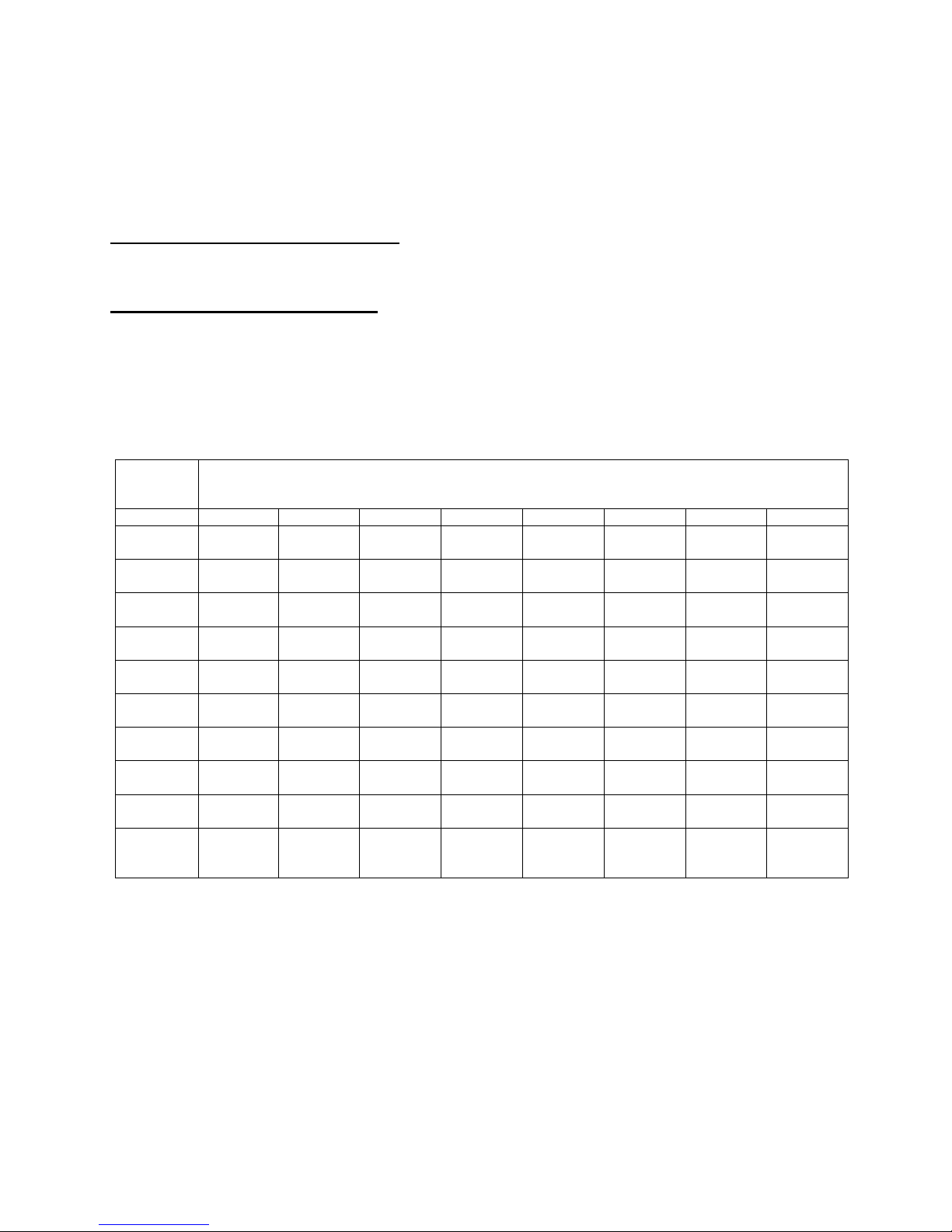
1.3 CLEARANCES TO COMBUSTIBLES AND FLOOR PROTECTOR
To install your appliance correctly, it is extremely important to respect all clearances to any
combustibles as indicated on your stove’s certification label.
Clearances to combustible materials
(see figure 1.3 to match each letter to a clearance)
For mobile home installation
Outside air kit with a listed double wall connector(CAN: ULC S641; USA: UL103) and
listed compatible chimney system(CAN: ULC S629; USA: UL103HT)
Use clearances from combustibles specified in the double wall connector installation.
MODEL A B C D E F K L
XVR-I
XVR-I SE
XVR-II
XVR-III
XLT-I
XLT-II
XTD 1.1
XTD 1.5
XTD 1.9
NXT-I
18’’
(460 mm)
18’’
(460 mm)
20’’
(510 mm)
18’’
(460 mm)
18’’
(460 mm)
20’’
(510 mm)
17’’
(435 mm)
14’’
(360 mm)
14’’
(360 mm)
14’’/10’’
(360/255
mm)
18’’
(460 mm)
18’’
(460 mm)
19’’
(485 mm)
22’’
(560 mm)
18’’
(460 mm)
19’’
(485 mm)
15’’
(385 mm)
12’’
(305 mm)
12’’
(305 mm)
14’’
(360 mm)
CLEARANCES (SINGLE WALL PIPE)
CANADA & USA
12’’
(305 mm)
12’’
(305 mm)
14’’
(360 mm)
16’’
(410 mm)
12’’
(305 mm)
14’’
(360 mm)
10’’
(255 mm)
7’’
(180 mm)
7’’
(180 mm)
7’’/6’’
(180/155
mm)
21’’
(535 mm)
21’’
(535 mm)
23’’
(585 mm)
21’’
(535 mm)
21’’
(535 mm)
23’’
(585 mm)
21’’
(535 mm)
18’’
(460 mm)
18’’
(460 mm)
18’’/14’’
(460/360
mm)
28’’
(715 mm)
28’’
(715 mm)
29’’
(740 mm)
29’’
(740 mm)
28’’
(715 mm)
29’’
(740 mm)
23’’
(585 mm)
22’’
(560 mm)
22’’
(560 mm)
23’’
(585 mm)
21’’
(535 mm)
21’’
(535 mm)
24’’
(610 mm)
24’’
(610 mm)
21’’
(535 mm)
24’’
(610 mm)
20’’
(510 mm)
18’’
(460 mm)
18’’
(460 mm)
18’’/17’’
(460/435
mm)
48’’
(1220 mm)
48’’
(1220 mm)
48’’
(1220 mm)
48’’
(1220 mm)
48’’
(1220 mm)
48’’
(1220 mm)
48’’
(1220 mm)
48’’
(1220 mm)
48’’
(1220 mm)
48’’
(1220 mm)
84’’
(213 cm)
84’’
(213 cm)
84’’
(213 cm)
84’’
(213 cm)
84’’
(213 cm)
84’’
(213 cm)
84’’
(213 cm)
84’’
(213 cm)
84’’
(213 cm)
84’’
(213 cm)
6
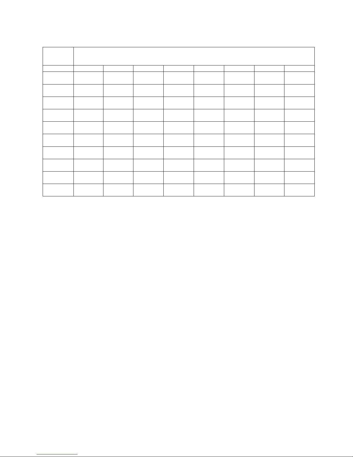
MODEL A B C D E F K L
XVR-I
XVR-I SE
XVR-II
XVR-III
XLT-I
XLT-II
XTD 1.1
XTD 1.5
XTD 1.9
NXT-I
18’’
(460 mm)
18’’
(460 mm)
20’’
(510 mm)
18’’
(460 mm)
18’’
(460 mm)
20’’
(510 mm)
12’’
(305 mm)
6’’
(155 mm)
6’’
(155 mm)
6’’
(155 mm)
18’’
(460 mm)
18’’
(460 mm)
19’’
(485 mm)
22’
(560 mm)
18’’
(460 mm)
19’’
(485 mm)
12’’
(305 mm)
11’’
(280 mm)
12’’
(305 mm)
12’’
(305 mm)
CLEARANCES (DOUBLE WALL PIPE)
CANADA & USA
12’’
(305 mm)
12’’
(305 mm)
14’’
(360 mm)
16’’
(410 mm)
12’’
(305 mm)
14’’
(360 mm)
7’’
(180 mm)
5’’
(130 mm)
5’’
(130 mm)
6’’
(155 mm)
21’’
(535 mm)
21’’
(535 mm)
23’’
(585 mm)
21’’
(535 mm)
21’’
(535 mm)
23’’
(585 mm)
16’’
(410 mm)
10’’
(255 mm)
10’’
(255 mm)
10’’
(255 mm)
28’’
(715 mm)
28’’
(715 mm)
29’’
(740 mm)
29’’
(740 mm)
28’’
(715 mm)
29’’
(740 mm)
20’’
(510 mm)
21’’
(535 mm)
22’’
(560 mm)
21’’
(535 mm)
21’’
(535 mm)
21’’
(535 mm)
24’’
(610 mm)
24’’
(610 mm)
21’’
(535 mm)
24’’
(610 mm)
17’’
(435 mm)
16’’
(410 mm)
16’’
(410 mm)
17’’
(435 mm)
48’’
(1220 mm)
48’’
(1220 mm)
48’’
(1220 mm)
48’’
(1220 mm)
48’’
(1220 mm)
48’’
(1220 mm)
48’’
(1220 mm)
48’’
(1220 mm)
48’’
(1220 mm)
48’’
(1220 mm)
84’’
(213 cm)
84’’
(213 cm)
84’’
(213 cm)
84’’
(213 cm)
84’’
(213 cm)
84’’
(213 cm)
84’’
(213 cm)
84’’
(213 cm)
84’’
(213 cm)
84’’
(213 cm)
7
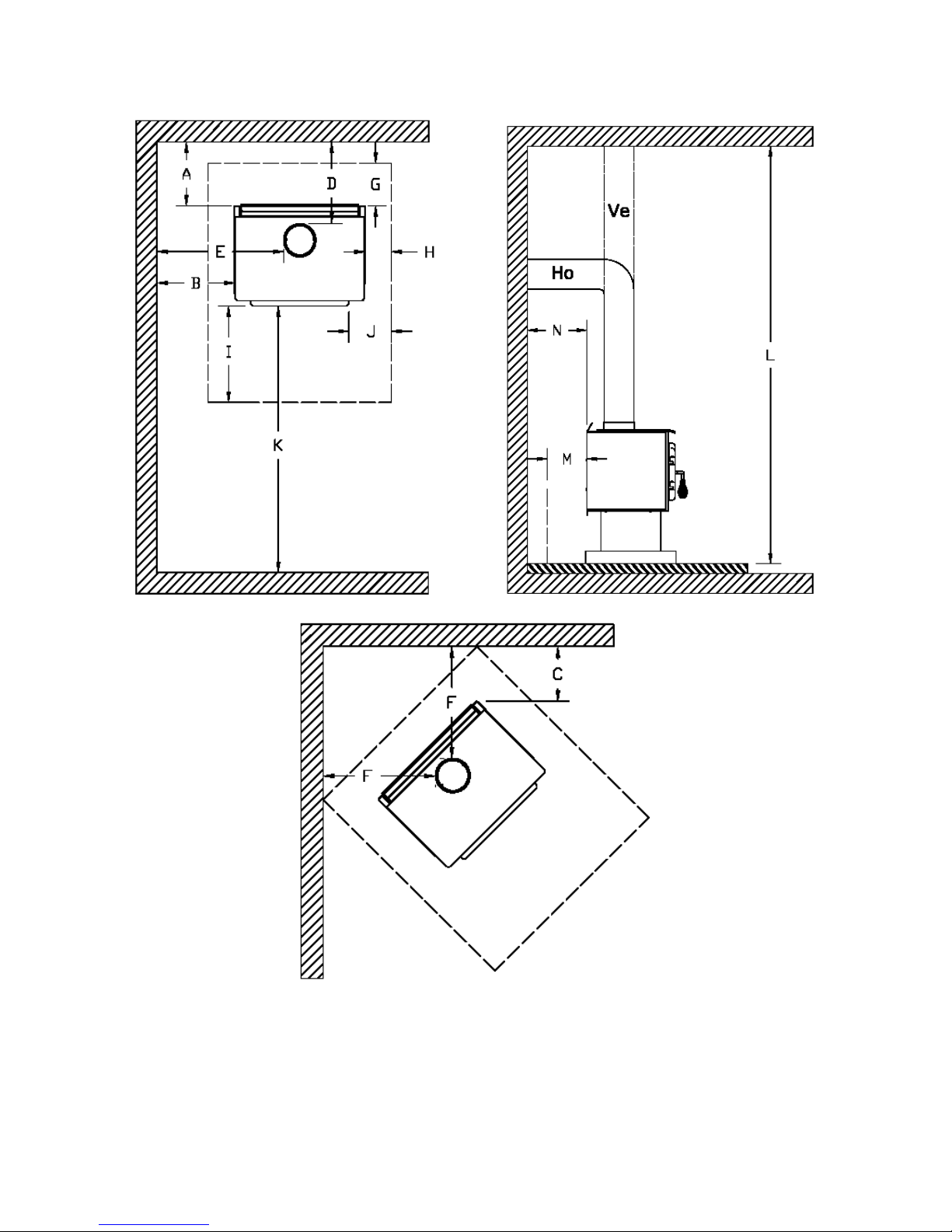
FIGURE 1.3 Clearances to combustible materials and floor protection
8
Floor protector
If the stove is to be installed on top of a combustible floor, it must be guarded by a non
combustible material as shown on figure 1.3 (see the dotted line area).
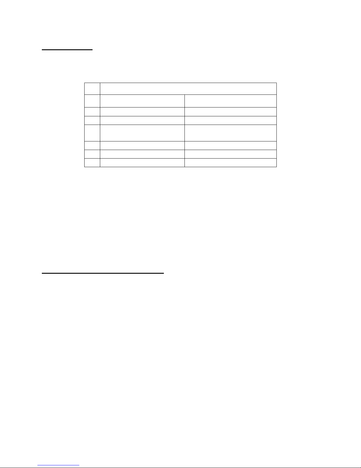
CANADA USA
FLOOR PROTECTOR*
G
H
J
M
N
8’’ (203 mm) – Note 1 N/A (Canada only)
8’’ (203 mm) N/A (Canada only)
I
18’’ (457 mm)
From door opening
16’’ (406 mm)
From door opening
N/A (USA only) 8’’ (203 mm)
8’’ (203 mm) N/A (Canada only)
N/A (USA only) Note 2
*Steel with a minimum thickness of 0.015’’ (0.38 mm) or ceramic tiles sealed together
with grout. No protection is required if the unit is installed on a non-combustible floor (ex:
concrete).
Note 1: The floor protection at the back of the stove is limited to the stove’s required
clearance if such clearance is smaller than 8 inches (203 mm).
Note 2: Only required under the horizontal section of the connector. Must exceed
each side of the connector by at least 2 inches (51 mm).
Reduced clearances using shielding
You may decrease the clearances by installing heat radiation shields between the walls or
the ceiling and the stove. These heat radiation shields must be installed permanently, and
can include sheet metal, a rigid non-combustible sheet or a masonry wall.
Clearances of not less than 1" (25 mm) and not more than 3" (76 mm) between the bottom
of the shield and the floor and not less than 3" (76 mm) between the top of the shield and
the ceiling must be respected to allow vertical air circulation behind the shield. The shield
must extend 20" (500 mm) above the stove top and 18" (450mm) to each side of the stove
(see graphic 1).
Following the installation of such a heat radiation shield, the clearances mentioned on the
stove certification plate may be reduced as stated in the following table.
9
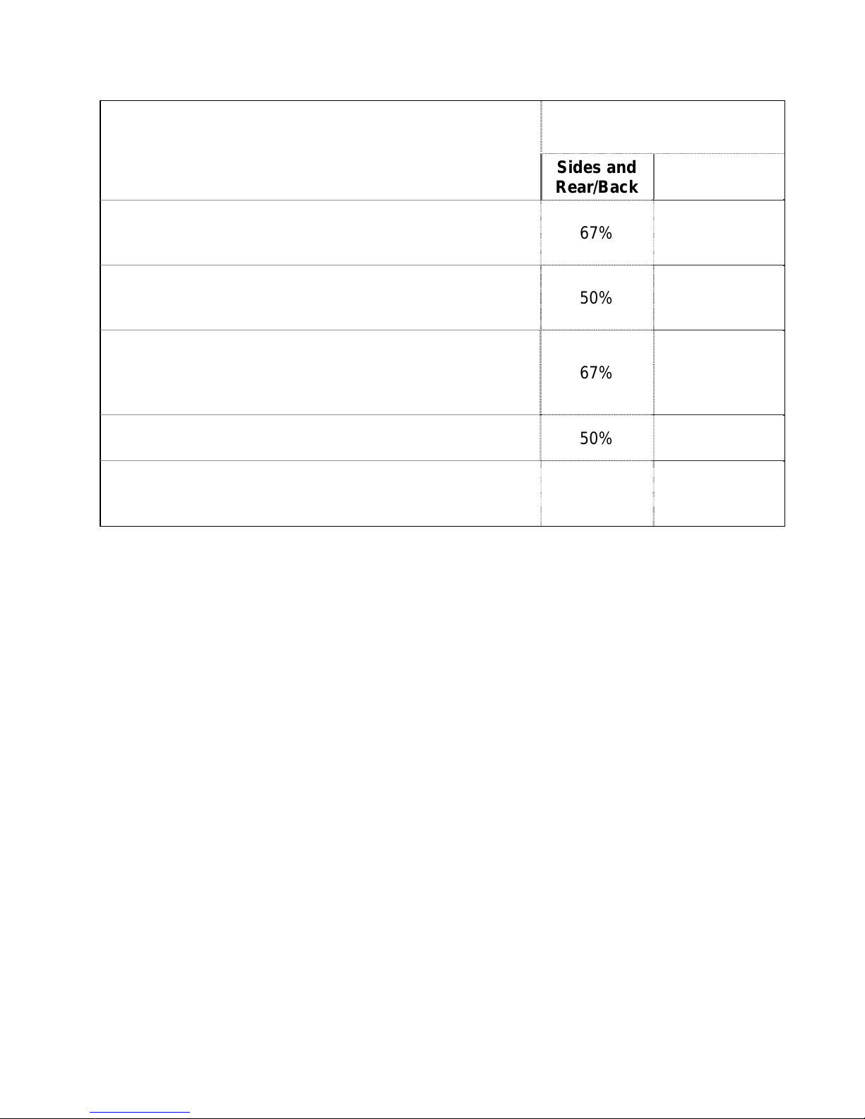
TYPE OF PROTECTION
Sheet metal, a minimum of 0,024" (0,61mm) spaced out
at least 1" (25mm) by non-combustible spacers
(see graphic 2).
Ceramic tiles, or an equivalent non-combustible material
on fire-proof supports spaced out at least 1" (25 mm) by
non-combustible spacers (see graphic 3).
Ceramic tiles, or an equivalent non-combustible material
on fire-proof supports with a minimum of 0,024" (0,61
mm) sheet metal backing spaced out at least 1" (25 mm)
by non-combustible spacers (see graphic 4)
Reducing Clearances
With Shielding
Sides and
Rear/Back
67% 50%
50% 33%
67% 50%
Top
Brick spaced out at least 1" (25 mm) by non-combustible
spacers (see graphic 5)
Brick with a minimum of 0,024" (0,61 mm) sheet metal
backing spaced out at least 1" (25 mm) by noncombustible spacers (see graphic 6).
50% N/A
67% N/A
10
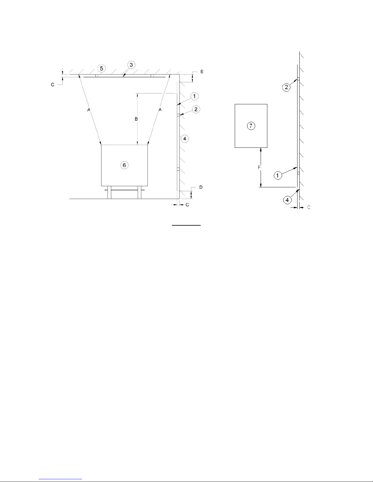
Graphic 1
A- Minimum clearance required between the appliance and an unshielded combustible
ceiling.
B- 20 in. (500 mm) minimum;
C- 1 in. (25 mm) minimum;
D- Between 1 in. and 3 in. (25 mm and 75 mm);
E- 3 in.(75 mm) minimum;
F- 18 in. (457 mm) minimum.
1- Shielding;
2- Non-combustible spacers;
3- Ceiling protector;
4- Combustible wall;
5- Ceiling;
6- Appliance (side view);
7- Appliance (top view).
11
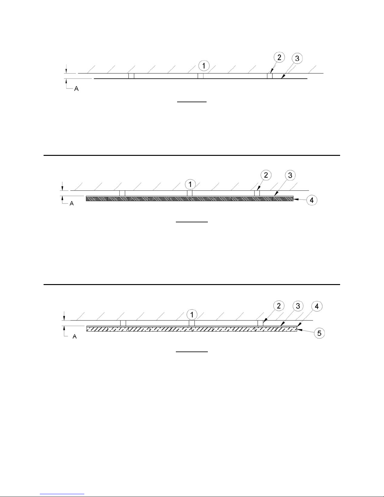
Graphic 2
A- 1 in.(25 mm) minimum;
1- Combustible wall;
2- Non-combustible spacers;
3- 0.024’’ (0.61mm) sheet metal.
Graphic 3
A- 1 in. (25 mm) minimum;
1- Combustible wall;
2- Non-combustible spacers;
3- Non-combustible support;
4- Ceramic tile or non-combustible material.
A- 1 in. (25 mm) minimum;
1- Combustible wall;
2- Non-combustible spacer;
3- 0.024’’ (0.61 mm) thick sheet metal;
4- Non-combustible support;
5- Ceramic tile or non-combustible material.
Graphic 4
12
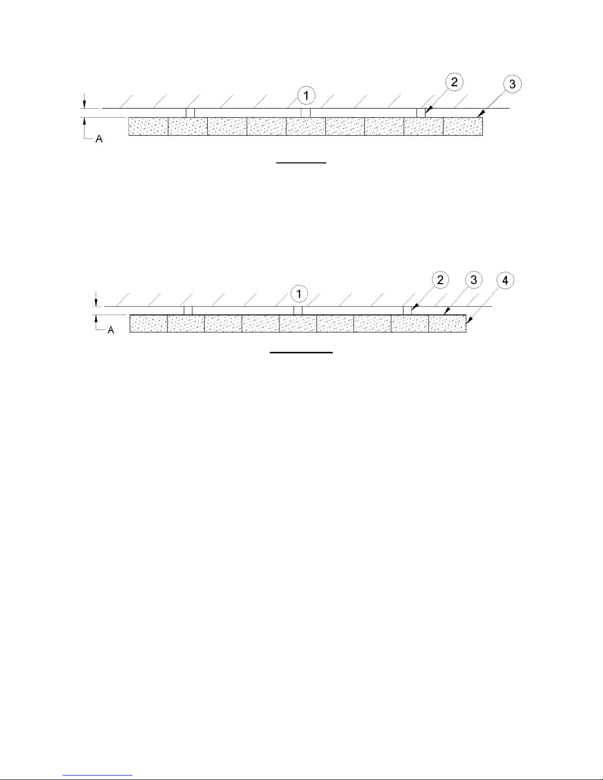
Graphic 5
A- 1 in. (25 mm) minimum;
1- Combustible wall;
2- Non-combustible spacers;
3- Brick.
__________________________________________________________________
Graphique 6
A- 1 in. (25 mm) minimum;
1- Combustible wall;
2- Non-combustible spacers;
3- 0.024’’ (0.61 mm) thick sheet metal;
4- Brick.
13

SECTION 2.0 CHIMNEY (FLUE SYSTEM)
2.1 DEFINITIONS
For clarity, the following definitions should be used with respect to these instructions:
A chimney system consists of a connector off the top of the stove, and a chimney, which
attaches to the connector and terminates outside the house.
A chimney can be a masonry chimney (of masonry construction with an inside liner), or a
factory built chimney.
A factory built chimney can be a double walled chimney (two concentric pipes with
insulation - sometimes referred to as an insulated solid pack) or an air cooled chimney
(three concentric pipes, with insulation between the first and second pipes, and air between
the second and third pipes).
A single walled connector is a single pipe.
A double walled connector has two concentric pipes, no insulation, and is an air cooled
connector.
2.2 CHIMNEY
CAUTION:
DO NOT fill any framed space around the factory-built chimney with insulation or any other
material. Insulation placed in this area could cause adjacent combustibles to overheat.
Do not use makeshift comprom ises during installation as they may be safety hazards, and a
fire could result.
Do not connect this unit to a chimney system serving another appliance.
Do not cut rafters or ceiling joists without first consulting a building official to ensure
structural integrity is not compromised.
14

Your wood stove may be hooked up with a factory built or masonry chimney. If you are using a
factory built chimney, it must comply with UL103 (USA) or ULCS629 (Canada) standards. It must
therefore be a 6” (152mm) HT Type (2100°F) chimney. It is extremely important that it be installed
according to the manufacturer's specifications. The manufacturers’ installation instructions and
specified clearances should always be followed in accordance with local and national installation
codes. In Canada the CSA B365 and the CSA C22.1 installation codes are to be followed. In the
USA the ANSI NFPA 70 and ANSI NFPA 211 installation codes are to be followed.
If you are using a masonry chimney, it is important that it be built in compliance with the
specifications of the Building Code. It must be lined with fire clay bricks, or clay tiles, sealed
together with fire cement, or have a listed solid fuel burning stainless steel liner. Round chimneys
are the most efficient.
The interior diameter of the chimney should be identical to the stove's smoke exhaust. A chimney
which is too small may cause draft problems, since it may not have the required volume to properly
evacuate the quantity of smoke resulting from the combustion. A chimney whish is too large may
also cause draft problems. In fact, a large chimney will be harder to warm-up and may not reach high
enough temperatures to create a proper draft effect. Note that it is the chimney which creates the
draft effect, not your stove. Your stove's performance is therefore directly dependent on an
adequate draft from your chimney.
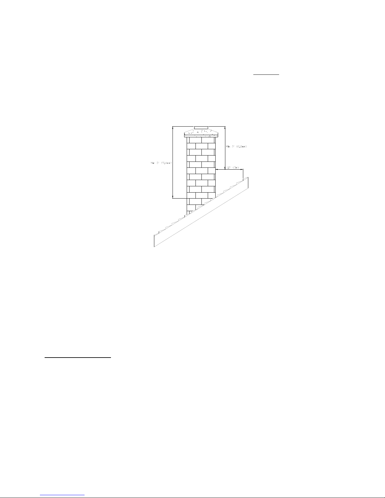
The following recommendations may be useful for the installation of your chimney:
Do not connect your stove to a chimney serving another appliance.
The chimney must rise above the roof at least 3' (0.9 mm) from the uppermost point of
contact. See Figure 2.2.
The chimney must exceed any part of the build ing or other obstruction within a 10' (3.04 m)
distance by a height of at least 2' (0.6 m). See Figure 2.2.
The minimum overall height of the chimney system, measured from the stove top to the
exterior termination cap of the chimney should be at least 12' (3.66m). A chimney which is
too short may lack the “tunnel effect” required to obtain a proper draft.
Installation of an interior chimney is always preferable to an exterior chimney. Chimneys
constructed outside of the home on an exterior wall should be avoided if possible, especially
in colder climates. The gas which circulates into an interior chimney will cool more slowly,
thus reducing the build-up of creosote and the risk of flue fires.
All else being equal, cooler chimneys will have less draft than hotter ones. This problem will
be amplified if the chimney is excessively long. A chimney which is excessively long may be
very hard to warm-up due to its higher volume. A cool chimney may even down draft
(reverse flow) due to the difficulty in heating it up to operating temperature while trying to
evacuate the stack gases.
15
If an exterior chimney is used, the best results will be obtained by using a connector
vertically off the unit to the highest possible point before elbowing off horizontally to the
exterior chimney. For efficiency and safety reasons the stove must not be installed with an
insulated chimney connected directly to the appliance.
Using a fire screen at the extremity of the chimney requires regular inspection in order to
insure that it is not obstructed, thus blocking the draft. It should be cleaned when necessary.
FIGURE 2.2 Minimum Height of the Chimney
2.2.1 Step by step installation of your factory-built chimney
The way to install your chimney may vary from one chimney manuf acturer to another. The instructions
contained in this manual are based on the recommendations of chimney manufacturers whose products
are sold at many North American retailers of wood stoves and related heating accessories.
Wall support system
If your chimney must rise along an outside wall, you need to connect it to your stove through an
adjacent wall. For this type of installation, the following items are normally required :
16
 Loading...