

Flame Energy FP-45 Owner's Manual
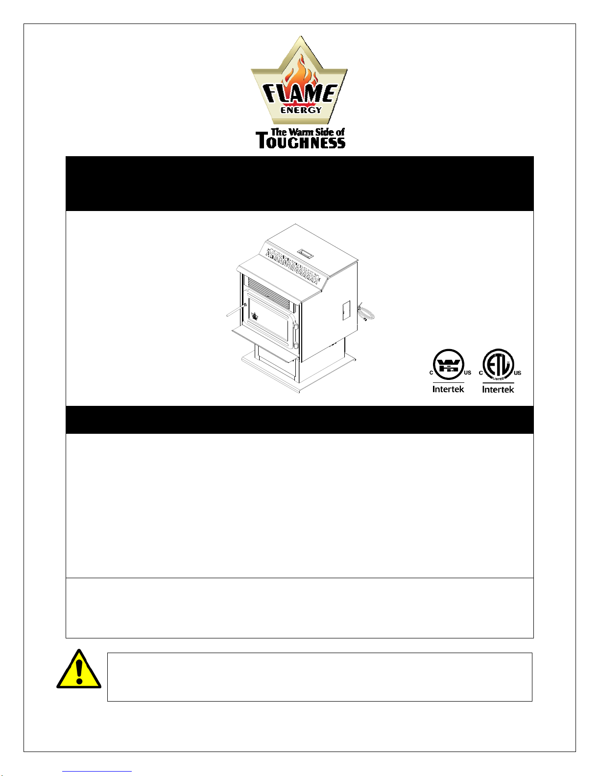
MODEL FP-45
FREESTANDING
OWNER’S MANUAL
Warning: If your appliance is not properly installed, a house fire may result. For your safety, follow the
installation directions. Contact local building or fire officials about restrictions and installation inspection
requirements in your area.
Please read this entire manual before installation and use of this pellet fuel-burning room heater. Failure
to follow these instructions could result in property damage, bodily injury, or even death.
Save these instructions.
Some surfaces become hot at higher feeding rates. To prevent potential burns, avoid contact with those
areas.
This heating appliance must serve as a supplementary heat source. An alternative heat source should be
available in the home if needed. The manufacturer cannot be responsible for additional heating costs
associated with the use of an alternative heat source.
It is highly recommended that the user buys this product from a retailer who can provide installation and
maintenance advice.
Professional installation is highly recommended
Thismanual isavailable forfree downloadonthemanufacturer’swebsite.Itisa copyrighteddocument.Re‐saleis
strictly prohibited. The manufacturer may update this manual from time to time and cannot be responsible for
problems, injuries, or damages arising out of the use of information contained in any manual obtained from
unauthorizedsources.
Manufactured by:
Stove Builder International Inc.
Quebec City (Quebec) CANADA
45259A
Printed in Canada 01-12-2011

INTRODUCTION
Thank you for purchasing the FP-45 pellet stove. You are now prepared to burn wood in the most
efficient, convenient way possible. To achieve the safest, most efficient and most enjoyable
performance from your stove, you must do three things: 1) Install it properly; 2) Operate it correctly;
and 3) Maintain it regularly. The purpose of this manual is to help you do all three.
PLEASE read this entire manual before installation and use of this pellet fuel-burning room
heater. Failure to follow these instructions could result in property damage, bodily injury or
even death.
Keep this manual handy for future reference.
Your FP-45 has been independently tested to ASTM E1509-95 Standard Specification for Room
Heaters, Pellet Fuel Burning Type 1, UL 1482-1998 and ULC-S627-00 Standard for Solid Fuel Room
Heaters, Oregon Administrative Rules for Mobile Homes (814-23-900 through 814-23-909) and
Installation as a Stove Heater.
This pellet stove, when installed, must be electrically grounded in accordance with local codes, or in
the absence of local codes, with the National Electrical Code, ANSI/NFPA 70 and CSA-C22.1.
This appliance is designed for use with pelletized wood only. Do not burn coal of any type in this
appliance. It is designed for residential installation according to current national and local building
codes as a freestanding or insert room heater. It is also approved as a mobile home heater which is
designed for connection to an outside combustion air source.
The stove will not operate using natural draft or without a power source for the blowers and fuel feed
system.
This stove is designed to provide the optimum proportions of fuel and air to the fire in order to burn
free of smoke and soot. Any blockage of the air supply to or from the stove will seriously degrade its
performance and will be evidenced by a smoking exhaust and a sooting window. For best operation,
the ash content of the pellet fuel should be less than 1% and the calorific value approximately 8,200
BTU/LB. Avoid burning high ash content fuels because this will rapidly fill up the burn pot and
eventually cut off the combustion air supply.
We recommend that our pellet hearth products be installed and serviced by professionals who are
certified in the United States by NFI (National Fireplace Institute®) or in Canada by WETT (Wood
Energy Technical Training) or in Quebec by APC (Association des Professionnels du Chauffage).
The FP-45 should not be used for commercial or industrial applications since operational control is
often not well managed in these settings
WARNING: T
HE INFORMATION GIVEN ON THE CERTIFICATION LABEL AFFIXED TO THE APPLIANCE ALWAYS
OVERRIDES THE INFORMATION PUBLISHED, IN ANY OTHER MEDIA (OWNER’S MANUAL,
CATALOGUES, FLYERS, MAGAZINES AND/OR WEB SITES).
2
SAFETY PRECAUTIONS
Do not operate your stove if you
smell smoke coming from it. Turn it off,
monitor it, and call your dealer. DO NOT
UNPLUG IT
Never use gasoline, gasoline-type
lantern fuel, kerosene, charcoal lighter fluid, or
similar liquids to start or “freshen up” a fire in
this stove. Keep all such liquids well away from
the stove while in use.
Never block free airflow through the
open vents of the stove.
Keep foreign objects out of the hopper.
Do not throw this manual away. This
manual has important operating and maintenance
instructions that you will need at a later time.
Always follow the instructions in this manual.
Do not place clothing or other
flammable items on or near the stove.
Never try to repair or replace any
part of the stove unless instructions are given
in this manual. All other work should be done
by a trained technician.
The stove will not operate during a
power outage. If an outage does occur, check
the stove for smoke spillage and open a
window if any smoke spills into the room.
Disconnect the power cord before
performing any maintenance or repairs on the
stove.
NOTE: Turning the stove “off” does not
disconnect all power from the stove.
Do not unplug the stove if you
suspect a malfunction. Turn the stove off,
inspect it, and call your dealer.
The viewing door must be closed and
latched during operation.
Do not operate the stove if the flame
becomes dark and sooty or if the burnpot overfills
with pellets. Turn the stove off, inspect it, and call
your dealer.
Do not touch the hot surfaces of the
heater. Educate all children of the danger of a
high temperature stove. Young children should be
supervised when they are in the same room as
the stove.
High ambient temperature in summer
time may cause the heat sensors on the stove to
activate the blowers, disconnect the stove when
not used for extended periods..
Contact your local building officials to
obtain a permit and information on any
installation restrictions or inspection
requirements in your area. Notify your
insurance company.
This unit must be properly installed to
prevent the possibility of a house fire. The
instructions must be strictly adhered to. Do not
use makeshift methods or compromise in the
installation.
Allow the stove to cool before
carrying out any maintenance or cleaning.
Ashes must be disposed or stored in a metal
container with a tight lid and placed on a non
combustible surface well away from the home
structure.
This stove must be connected to a
standard 120 V., 60 Hz grounded electrical
outlet. Do not use an adapter plug or sever the
grounding plug. Do not route the electrical cord
underneath, in front of, or over the stove.
The exhaust system should be
checked, at least twice a year for any build up
of soot or creosote.
The exhaust system must be
completely airtight and properly installed. All vent
connector joints must be sealed and fastened in
accordance with the pellet pipe manufacturer's
instructions to ensure consistent performance and
avoid smoke and ash spillage.
Your stove requires maintenance and
cleaning. Failure to maintain your stove may lead
to smoke spillage in your home.
This stove is designed and approved for
pelletized wood fuel only. Any other type of fuel
burned in this heater will void the warranty.
When installed in a mobile home, the
stove must be bolted to the floor, have outside air,
and NOT BE INSTALLED IN A BEDROOM (Per
H.U.D. requirements). Check with local building
officials.
Stove Builder International Inc.
grants no warranty, implied or stated, for the
installation or maintenance of your stove, and
assumes no responsibility of any
consequential damage(s).
3

TABLE OF CONTENTS
INTRODUCTION ..................................................................................................................................................................... 2
SAFETY PRECAUTIONS ....................................................................................................................................................... 3
TABLE OF CONTENTS .......................................................................................................................................................... 4
INSTALLATION ...................................................................................................................................................................... 6
FP-45 FREESTANDING PELLET STOVE ....................................................................................................... 6
PREPARATION .................................................................................................................................................. 6
CLEARANCES TO COMBUSTIBLES AND FLOOR PROTECTOR .............................................................. 6
COMBUSTION AIR SUPPLY ........................................................................................................................... 7
WHEN OUTSIDE AIR IS NOT USED .............................................................................................................. 7
VENTING ............................................................................................................................................................ 7
EQUIVALENT VENT LENGHT (EVL) ............................................................................................................ 8
INSTALLATION CONFIGURATIONS ............................................................................................................ 8
A. HORIZONTALLY THROUGH WALL (Refer to Figures 7, 8, or 10) .................................................. 8
B. VERTICALLY WITH NEW CHIMNEY SYSTEM (Refer to Figure 9 – Venting through roof) ......... 9
C. VERTICALLY INTO EXISTING CHIMNEY SYSTEM ...................................................................... 9
VERTICALLY INTO EXISTING MASONRY FIREPLACE ..................................................................... 10
INSTALLATION THROUGH SIDE OF MASONRY CHIMNEY ............................................................. 10
OPTIONAL LOG SET INSTALLATION ........................................................................................................ 11
FILTERS INSTALLATION AND CLEANING ............................................................................................... 12
OPERATION ......................................................................................................................................................................... 13
PROPER FUEL .................................................................................................................................................. 13
PRE-START-UP CHECK ................................................................................................................................. 13
BUILDING A FIRE ........................................................................................................................................... 13
LIGHTING PROCEDURE ................................................................................................................................ 13
UNIT CONTROLS ............................................................................................................................................ 13
MODE SWITCH ................................................................................................................................................ 14
FUEL FEED SWITCH ...................................................................................................................................... 14
NOISE REDUCER ............................................................................................................................................ 14
HEAT LEVEL ................................................................................................................................................... 14
RESET ............................................................................................................................................................... 14
OPENING DOOR .............................................................................................................................................. 14
CONVECTION BLOWER (ROOM AIR FAN) ............................................................................................... 14
COMBEXtm ........................................................................................................................................................ 14
IF THE STOVE RUNS OUT OF PELLETS ..................................................................................................... 15
DAMPER CONTROL ....................................................................................................................................... 15
REFUELING ..................................................................................................................................................... 15
SHUTDOWN PROCEDURE ............................................................................................................................ 15
SAFETY FEATURES ....................................................................................................................................... 15
OPERATING THE STOVE USING A THERMOSTAT ................................................................................. 16
THERMOSTAT INSTALLATION ................................................................................................................... 16
THERMOSTATIC MODE ............................................................................................................................ 16
4

OPERATING SAFETY PRECAUTIONS .............................................................................................................................. 17
MAINTENANCE .................................................................................................................................................................... 18
ASH REMOVAL ............................................................................................................................................... 18
ASH DISPOSAL ................................................................................................................................................ 18
VACCUM USE .................................................................................................................................................. 19
CLEANING ....................................................................................................................................................... 19
BLOWERS AND PRESSURE SWITCH PROBE ............................................................................................ 19
CHIMNEY CLEANING .................................................................................................................................... 20
RECOMMENDED MAINTENANCE SCHEDULE ........................................................................................ 20
REMOVAL AND REPLACEMENT OF DOOR GLASS ................................................................................ 20
TROUBLESHOOTING .......................................................................................................................................................... 21
STOVE SHUTS OFF AND SHOWS WARNING CODE “P” ......................................................................... 21
STOVE SHUTS OFF AND SHOWS WARNING CODE “E” ......................................................................... 22
STOVE FEEDS PELLETS, BUT WILL NOT IGNITE AND SHOWS WARNING CODE “L” ................... 23
STOVE FEEDS PELLETS, BUT WILL NOT IGNITE AND SHOWS WARNING CODE “I” ..................... 23
STOVE STOPS FEEDING PELLETS AND SHOWS WARNING CODE “O” ............................................. 23
STOVE STOPS FEEDING PELLETS AND SHOWS WARNING CODE “H” ............................................. 24
STOVE STOPS FEEDING PELLETS AND SHOWS WARNING CODE “d” .............................................. 24
SMOKE SMELL COMING BACK INTO THE HOME .................................................................................. 24
AUGER MOTOR STOPS FEEDING PELLETS AND COMES BACK ON .................................................. 24
GLASS SOOTS UP VERY FAST .................................................................................................................... 25
FLAME IS LAZY, DARK, AND HAS BLACK TIPS ..................................................................................... 25
AFTER STOVE HAS BEEN ON FOR A WHILE, THE BURNPOT OVERFILLS ....................................... 25
WARNING CODES .......................................................................................................................................... 26
SMOKE SMELL OR SOOT BUILD-UP .......................................................................................................... 26
ELECTRICAL DIAGRAM ..................................................................................................................................................... 27
ELECTRIC SHOCK .......................................................................................................................................... 27
REPLACEMENT PARTS ...................................................................................................................................................... 28
APPENDIX A - HORIZONTAL AND VERTICAL VENT CHART ......................................................................................... 29
APPENDIX B – INSPECTION AND REPAIR FORM ........................................................................................................... 30
FLAME LIMITED LIFETIME WARRANTY ........................................................................................................................... 32
REGISTER YOU WARRANTY ONLINE
To receive full warranty coverage, you will need to show evidence
of the date you purchased your unit. Keep your sales invoice.
We also recommend that you register your warranty online at
http://www.flame-intl.com/warranty-registration.aspx
Registering your warranty online will help us track rapidly the
information we need on your unit.
5
INSTALLATION
FP-45 FREESTANDING PELLET STOVE
Width: 25 1/2”
Height: 33”
Depth: 28”
Weight: 230lbs.
Flue size: 3” or 4”
Hopper Capacity: Up to 80 lbs.
(This can vary slightly depending on pellet size, length, and diameter)
EPA status: exempt
Burn rate: 1.3 lb. to 5.5 lbs. per hour
BTU range: 8,200 to 45000
Electrical consumption: 3.5 Amps lighting cycle
2.5 Amps. continuous duty
Control board fuses: Main: 7.5A-250V fastblow
Igniter: 5A-250V fastblow
Electrical requirement: 120VAC 15A
Approved installations: mobile home, conventional
PREPARATION
Factory packaging must be removed, and some minor assembly work is
required prior to installation:
The black knob must be attached to heat exchanger rod;
The coil handle must be attached to the handle rod;
Filters may be inserted between finger guard and convection
blower (see “filters installation and cleaning” section).
CLEARANCES
Figure 1
CLEARANCES TO COMBUSTIBLES AND FLOOR PROTECTOR
The FP-45 has been tested and listed for installation in regular and mobile
homes.
In the USA, the unit must be installed on a non-combustible floor pad
extending at least 6 inches (155 mm) in front of the door opening and at
least 6 inches (155 mm) on each side of the door opening. In Canada, the
unit must be installed on a noncombustible floor pad extending at least 18
inches (460 mm) in front of the door opening and at least 8 inches (205
mm) at the back and on each side of the unit. The floor pad must have a
thickness of at least 0.015'' (0.38mm). NOTE: ceramic tile, or any tile, must
be laid on a continuous non combustible sheet to prevent the possibility of
embers falling through to the combustible floor if cracks or separation
should occur in the finished surface.
DO NOT USE MAKESHIFT MATERIALS OR COMPROMISES IN THE
INSTALLATION OF THIS UNIT.
INSTALL VENT WITH CLEARANCES SPECIFIED BY THE VENT
MANUFACTURER.
We recommend leaving 24’’ on each sides of the appliance in order to
facilitate access for maintenance.
A 2’’ (55 mm) 2’’ (55 mm)
B 6’’ (155 mm) 6’’ (155 mm)
C 2’’ (55 mm) 2’’ (55 mm)
D 3’’ (80 mm) 3’’ (80 mm)
CLEARANCES TO COMBUSTIBLES
CANADA USA
Figure 2
FLOOR PROTECTION
Dooropening
Figure 3
E 18’’ (460 mm) 6’’ (155 mm)
F N/A (USA only) 6’’ (155 mm)
G 8’’ (205 mm) N/A (Canada only)
H 8’’ (205 mm) N/A (Canada only)
FLOOR PROTECTION*
CANADA USA
6
COMBUSTION AIR SUPPLY
For a mobile home installation the stove must be connected to an outside
source of combustion air. A 3” inside diameter metallic pipe, either flexible
or rigid, may be attached to the inlet at the stove’s rear (refer to figures 4, 5
& 6). A rodent guard (minimum ¼” wire mesh) must be used at the
terminus (refer to figure 5). All connections must be secured and airtight by
either using the appropriately sized hose clamp and/or UL-181-AP foil tape.
For mobile home installations only: combustion air supply conduit may
not exceed 10 feet.
Sources of Outside Combustion Air
A hole in the wall behind the stove.(Figure 5)
A hole in floor near stove rear terminating only in a ventilated
crawl space.(Figure 6)
35
INTAKE
11
16
AIR
1
25
8
EXHAUST
7
1
9
2
11
8
WHEN OUTSIDE AIR IS NOT USED
If outside air is not used, it is important that combustion air be easily
available to the air inlet. A closable outside air register can be used in
tightly insulated homes.
VENTING
The FP-45 is certified for use with a vent certified to UL-103 or ULC S629M
and a chimney type vent certified to UL-641 or ULC-S-609-M89 and
ULC/ORD C441-M90, with 3” or 4” inner diameter. In Canada, we
recommend that you usea listed pellet vent that meets the ULC S-609-M89
and ULC/ORD C441-M90 Standards. For the United States, we
recommend that you use a listed pellet vent that meets the UL-641, 7
edition Standard. This unit can be vented in an existing chimney with the
addition of a liner if the chimney is more than 4” in diameter. Class “A”
chimney is not required. Refer to the instructions provided by the vent or
chimney manufacturer, especially when passing through a wall, ceiling or
roof.
Your venting system should have at least one foot of vertical rise for
each foot of horizontal run. The total vertical rise should ne ve r be
less than 3 feet (see Appendix A).
This is a pressurized exhaust system. All vent connector joints must be
sealed and fastened in accordance with the pellet pipe manufacturer's
instructions to ensure consistent performance and avoid smoke and ash
spillage.
DO NOT CONNECT THIS UNIT TO A CHIMNEY FLUE SERVING
ANOTHER APPLIANCE.
th
1
7
16
3
8
4
3
7
16
Figure 4
Rear view
TRIM
COLLAR
RODENT
GUARD
Figure 5
Fresh air supply
DO NOT INSTALL A FLUE DAMPER IN THE VENTING SYSTEM OF
THIS UNIT.
INSTALL VENT AT CLEARANCES SPECIFIED BY THE VENT
MANUFACTURER.
WARNING: DO NOT INSTALL IN BEDROOM
CAUTION: THE STRUCTURAL INTEGRITY OF THE MANUFACTURED
HOME FLOOR, WALL, AND CEILING/ROOF MUST BE MAINTAINED
7
VENTILATED
CRAWL SPACE
Figure 6
Ventilated crawl space
EQUIVALENT VENT LENGHT (EVL)
The longer the run of pipe in your installation, the greather the restriction in
the system. Therefore, larger diameter pipe should be used for longer
runs.
Use 4” pipe if you have more than 15 feet of Equivalent Vent Leng th
(EVL).
Horizontal runs shall not exceed 10 feet of EVL.
To calculate EVL, use the following conversions table:
Qty Type of pipe EVL equivalent(ft)
1 90° elbow or “T” 5
FOLLOW CHIMNEY OR
VENT MANUFACTURER'S
INSTRUCTIONS
WALL
THIMBLE
90 DEGREE ELBOW
45 DEGREE ELBOW
TERMINATION
COLLAR
WALL
STRAP
CLEAN OUT
TEE
1 45° elbow 3
1 ft Horizontal pipe run 1
1 ft Vertical pipe run 0.5
NOTE: At altitudes above 3,000 feet, we suggest the use of 4” diameter
vent at an EVL of 7 feet or more.
Here is an example on how to calculate the EVL of your installation. (See
Figure 8)
(3 x 4’ of vertical length = 12’ x 0.5 = 6 EVL) + (1 x elbow or "T" = 5 EVL) +
(2 x 1’ of horizontal length = 2 EVL)
Total EVL = (6 + 5 +2) = 13. So 3” diameter vent is acceptable.
Note: Do not count the outside termination (goose neck) in the EVL
calculation.
INSTALLATION CONFIGURATIONS
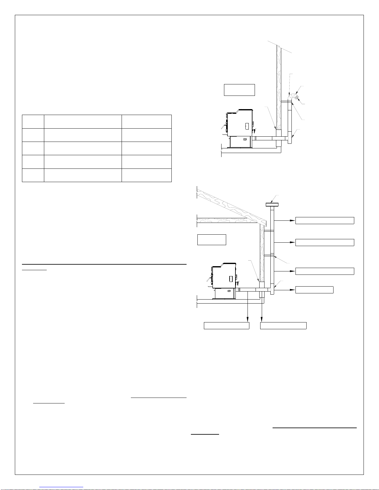
A. HORIZONTALLY THROUGH WALL (Refer to Figures 7, 8, or 10)
NOTE: Follow Vent chimney manufacturer’s instructions.
1. Position stove, adhering to clearances shown in Figures 1 & 2.
2. Determine position of hole in wall; directly behind stove exhaust vent
(refer to figure 4).
3. Always maintain 3” clearance from combustible materials.
4. Install Vent wall thimble per Vent manufacturer’s instructions.
5. Attach enough piping to penetrate and extend at least 6 inches
beyond the exterior wall. There should always be at least one foot of
vertical rise for each foot of horizontal run (see Appendix A). At least
3 feet of vertical rise are needed in all cases. A longer vertical rise
will favour a better exhaust.
6. To reduce the risk of smoke spillage, never terminate with a
horizontal run. If your system terminates with a horizontal run, add at
least 3 feet of vertical rise (see Appendix A).
7. Attach cap and seal outside wall thimbles with non-hardening
waterproof mastic.
Termination should not be located so that hot exhaust gases can ignite
trees, shrubs, or grasses or be a hazard to children. Exhaust gases can
reach temperatures of 500ºF and cause serious burns if touched.
Figure 7
Venting through wall
VERTICAL ROOF VENT
VERTICAL LENGTH 4' EVL = 4 X 0.5' = 2'
FOLLOW CHIMNEY OR
VENT MANUFACTURER'S
INSTRUCTIONS
1' HORIZONTAL RUN EVL = 1'
WALL
THIMBLE
1' HORIZONTAL RUN EVL = 1'
VERTICAL LENGTH 4' EVL = 4 X 0.5' = 2'
WALL
STRAP
VERTICAL LENGTH4' EVL = 4 X 0.5' = 2'
CLEAN OUT
TEE
90° ELBOW "T" LEE = 5'
Figure 8
Venting trough wall
Locate terminations: a) not less than 3 feet above any forced air inlet
located within 10 feet; b) not less than 4 feet below or horizontally from,
or one foot above, any door, window or gravity air inlet into any building;
c) not less than two feet from an adjacent building and not less than 7 feet
above grade when located adjacent to a public walkway. Mobile home
installations must use a spark arrester. Other restrictions may apply, such
as the need to maintain a minimum distance to a gas meter. US and
Canadian Standards may vary. Consult the vent manufacturer’s
instructions.
8

B. VERTICALLY WITH NEW CHIMNEY SYSTEM (Refer to Figure 9 –
Venting through roof)
NOTE: Follow Vent chimney manufacturer’s instructions.
OPTION: To achieve a centered vertical installation, a 45º elbow and a
clean-out tee can be used to offset the pipe from the exhaust outlet to the
rear center of the stove.
OPTION: Install Vent elbow in place of clean-out tee. Locate stove. Drop
plumb bob to center of tee outlet, mark point on ceiling. Install ceiling
support and Vent pipe per Vent manufacturer’s instructions.
1. Always maintain 3” clearance from combustible materials. When
passing through additional floors or ceilings, always install firestop
spacer.
2. After lining up for hole in roof, cut either a round or square hole in roof,
always 3” larger all the way around pipe. Install upper edge and sides
of flashing under roofing materials, nail to the roof along upper edge.
Do not nail lower edge. Seal nail heads with flexible waterproof
sealant.
3. Apply flexible, waterproof sealant where the storm collar meets the
vent. Slide storm collar down until it sits on the flashing. Seal and
install cap. Mobile home installations must use a spark arrester.
C. VERTICALLY INTO EXISTING CHIMNEY SYSTEM
As an alternative, 3” or 4” Vent can be run inside existing chimney to
termination (Figure 11). This is the preferred method.
Follow guidelines for equivalent vent length.
Figure 9
Venting through roof
FOLLOW CHIMNEY OR
VENT MANUFACTURER'S
INSTRUCTIONS
WALL THIMBLE
FOR BASEMENT INSTALLATION
A 4" PIPE IS RECOMMANDED
Figure 10
WALL
STRAP
CLEAN OUT
TEE
CLEAN OUT
TEE
Figure 11
Venting through existing chimney
Basement installation
9
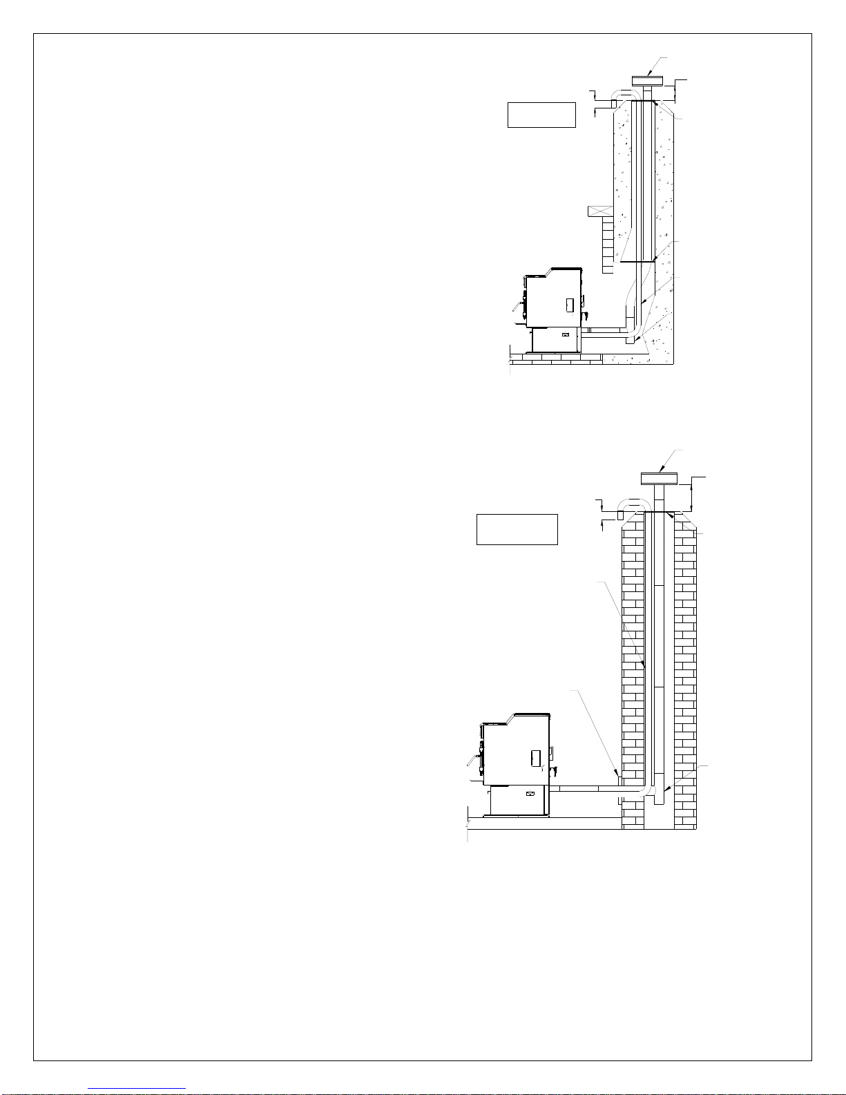
VERTICALLY INTO EXISTING MASONRY FIREPLACE
NOTE: Follow Vent chimney manufacturer’s instructions.
1. Have the masonry chimney inspected by a qualified chimney sweep
or installer to determine its structural integrity.
2. You must run a pipe from the stove outlet to 18 inches above the top
of the chimney.
3. Install a blanking plate and the chimney pipe, and if used the outside
air pipe, as shown in Figure 12.
4. Attach the DuraVent adapter, a section of pipe and clean out tee,
making sure the clean out tee is centered in the chimney flue area.
Use RTV, metallic tape, and a minimum of three self-taping screws at
all joint connections to ensure a tight seal.
5. Position the stove, adhering to the clearances in Figures 1 & 2.
Measure and build chimney top plate. Cut out holes for chimney pipe, and
if used the outside air pipe. Install and seal with flexible waterproof sealant
to prevent water leakage. Install vent cap.
INSTALLATION THROUGH SIDE OF MASONRY CHIMNEY
NOTE: Follow Vent chimney manufacturer’s instructions.
1. Position the stove, adhering to the clearances in Figures 1 & 2. Mark
the center of the hole where the pipe is to pierce the masonry
chimney.
2. It will be necessary to cut out the masonry around the location of the
pipe center mark. Cut a 4-inch diameter hole for 3-inch pipe and 5inch diameter hole for 4-inch pipe.
3. Measure and build chimney top plate. Cut out holes for chimney pipe,
and if used the outside air pipe.
4. Install the tee on the bottom of the vertical pipe system and lower it
down the chimney until the center branch of the tee is level with the
center of the hole in the masonry, as shown in Figure 13.
5. Install and seal the top plate from step 3 with flexible waterproof
sealant. Slip the storm collar over the pipe, and while holding the pipe
at the proper elevation, affix the collar with a minimum of three 1/4”
stainless steel sheet metal screws. Seal all joints and seams around
the collar.
6. Connect the horizontal pipe by pushing it through the hole in the
masonry and lining it up with the branch in the tee. Push the pipe into
the tee while twisting it to lock it into the tee.
7. If desired, once the horizontal pipe is in place, the space between the
pipe and masonry may be filled with high-temperature grout.
Install the trim collar. An adjustable pipe length and adapter may be
needed to align and complete the connection to the stove.
FOLLOW CHIMNEY OR
VENT MANUFACTURER'S
INSTRUCTIONS
Venting through masonry
FOLLOW CHIMNEY OR
VENT MANUFACTURER'S
INSTRUCTIONS
THIMBLE
Venting through side of
3"
Figure 12
chimney
3"
OPTIONAL
OUTSIDE AIR
WALL
Figure 13
masonry chimney
VERTICAL ROOF VENT
18"
TOP PLATE
BLANKING PLATE
OPTIONAL
OUTSIDE AIR
CLEAN OUT
TEE
VERTICAL ROOF VENT
18"
TOP PLATE
CLEAN OUT
TEE
10
 Loading...