

Flame XTD1.5-I, XTD1.9-I Owner's Manual
OWNER`S MANUAL
XTD1.5-I & XTD1.9-I Inserts
US ENVIRONMENTAL PROTECTION
AGENCY PHASE II CERTIFIED
WOOD INSERTS
Verified and tested following
ULC S628 and UL 1482 Standards
by:
Manufactured by : STOVE BUILDER INTERNATIONAL INC..
READ AND KEEP THIS MANUAL FOR REFERENCE
1700, Léon-Harmel, Québec (Québec) G1N 4R9
Tel : (418 ) 527-3060
Fax : (418 ) 527-4311
www.flame-intl.com
45272
INTRODUCTION
SBI INC., one of the most important wood stove and fireplace manufacturers in Canada,
congratulates you on your purchase and wishes to help you get maximum satisfaction from your
wood insert. In the pages that follow, we will give you advice on wood heating and controlled
combustion as well as technical specifications regarding installation, operation and maintenance of
the model you have chosen.
The instructions pertaining to the installation of your wood stove comply with ULC-S628 and UL1482 standards.
Read this entire manual before you install and use your new insert. If this insert is not
properly installed, a house fire may result. To reduce the risk of fire, follow the installation
instructions. Failure to follow instructions may result in property damage, bodily injury, or
even death.
Consult your municipal building department or fire officials about restrictions and
installations requirements in your area and the need to obtain a permit.
Keep and save this instructions manual for future references.
CAUTIONS:
• HOT WHILE IN OPERATION. KEEP CHILDREN, CLOTHING AND FURNITURE AWAY. CONTACT MAY CAUSE
SKIN BURNS.
• DO NOT USE CHEMICALS OR FLUIDS TO START THE FIRE.
• DO NOT LEAVE THE STOVE UNATTENDED WHEN THE DOOR IS SLIGHTLY OPENED.
• DO NOT BURN WASTES, FLAMMABLE FLUID SUCH AS GASOLINE, NAPHTHA OR MOTOR OIL.
• DO NOT CONNECT TO ANY AIR DISTRIBUTION DUCT OR SYSTEM.
• ALWAYS CLOSE THE DOOR AFTER THE IGNITION.
REGISTER YOUR WARRANTY ONLINE
To receive full warranty coverage, you will
need to show evidence of the date you
purchased your stove. Keep your sales
invoice. We also recommend that you
register your warranty online at
www.flame-intl.com Registering your
warranty online will help us track rapidly
the information we need on your stove.
1

TABLE OF CONTENTS
INTRODUCTION
...................................................................................................................................... 1
Section 1.0 Pre-Installation Requirements ............................................................................................. 5
1.1 Masonry & Zero Clearance Requirements .................................................................................. 5
1.2 Venting Requirements .................................................................................................................... 6
Section 2.0 Installation ............................................................................................................................. 7
2.1 Clearances To Combustibles (Measured From Insert Body) ..................................................... 7
2.1.1 Hearth Requirements .................................................................................................................. 8
2.2 Suitable Fireplace Dimensions ....................................................................................................... 8
2.3 Safety Information .......................................................................................................................... 9
2.4 Installation Instructions ............................................................................................................... 10
2.5 Air control plate, faceplate and fan Assembly Instructions..................................................... 11
2.6 Adapter for fresh air kit - installation instructions ................................................................... 12
Section 3.0 Operation ............................................................................................................................. 13
3.1 Safety Information ........................................................................................................................ 13
3.2 Fuel ................................................................................................................................................. 14
3.2.1 Simple Wood Moisture Test ...................................................................................................... 15
3.3 Notes About First Firing .............................................................................................................. 15
3.4 Lighting A Fire .............................................................................................................................. 15
3.5 Maintaining The Fire .................................................................................................................... 17
3.6 Fan Operation ............................................................................................................................... 17
Section 4.0 Maintenance ......................................................................................................................... 18
4.1 Care And Cleaning ....................................................................................................................... 18
4.1.1 Glass Cleaning and maintenance .............................................................................................. 18
4.2 Ash Removal .................................................................................................................................. 19
4.3 Chimney Cleaning ......................................................................................................................... 19
4.4 Baffle Installation for XTD1.5-I & XTD1.9-I ............................................................................. 20
4.5 Secondary Air Tube Replacement ............................................................................................... 22
4.6 Fan Maintenance & Care ............................................................................................................. 23
4.7 Removal instructions .................................................................................................................... 23
Section 5.0 Specifications ....................................................................................................................... 24
5.1 XTD1.5-I Model .......................................................................................................................... 24
5.2 XTD1.9-I Insert Model ............................................................................................................... 25
FLAME LIMITED LIFETIME WARRANTY ...................................................................... 26
2
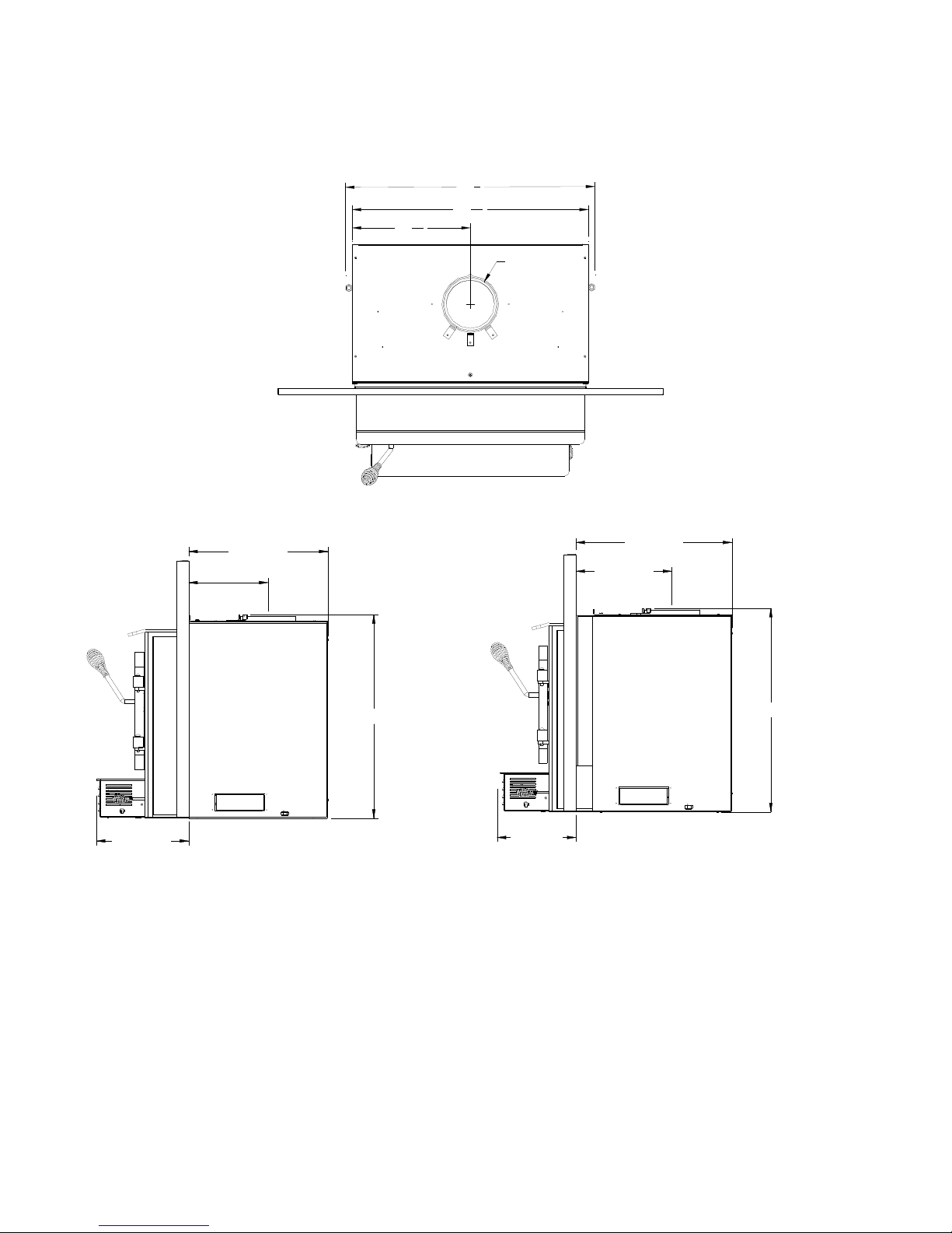
XTD1.5-I Dimensions
13
16
3
28
8
15
26
7
16
Ø6.000
15-1/32"
8-9/64"
20-31/32"
9-61/64"
13 3/8"
6-31/64"
20-31/32"
8-9/32"
Faceplate fully extended toward the back Faceplate fully extended toward the front
3
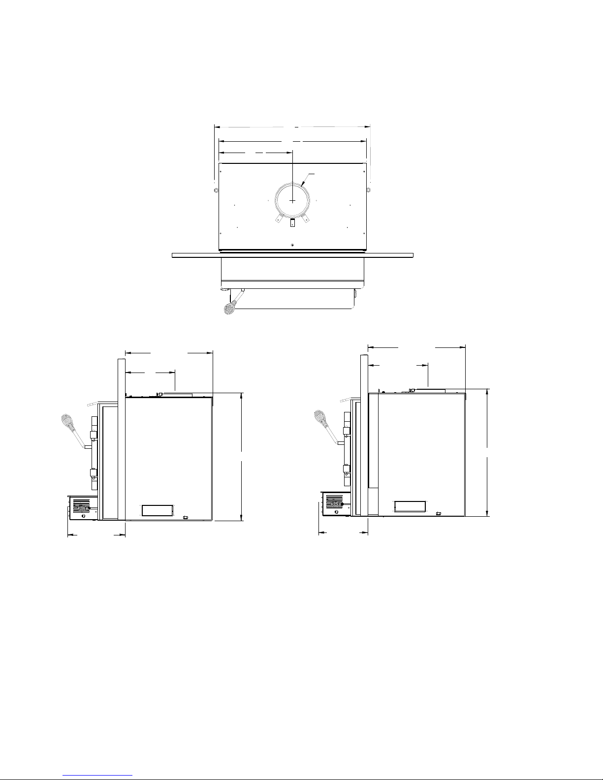
XTD1.9-I Dimensions
13
16
3
28
8
15
26
7
16
Ø6.000
17 11/16"
10 57/64"
23 3/64"
10 49/64"
15 13/16"
9"
23 1/32"
8 61/64"
Faceplate fully extended toward the back Faceplate fully extended toward the front
4

Section 1.0 Pre-Installation Requirements
1.1 Masonry & Zero Clearance Requirements
The masonry fireplace must meet the minimum code requirements, or NFPA 211 or the equivalent for a
safe installation. Contact your local Building Inspector for requirements in your area. An inspection of
the fireplace should include the following:
1. CONDITION OF THE FIREPLACE AND CHIMNEY: Examine the masonry fireplace and
chimney prior to installation to determine that they are free from cracks, loose mortar, creosote
deposits, blockage, or other signs of deterioration. If evidence of deterioration is noted, the fireplace
or chimney should be upgraded prior to installation.
2. ZERO CLEARANCE OR METAL HEATFORM FIREPLACE: These fireplaces and chimneys
must meet the conditions above, and the factory built zero clearance fireplace must be listed. They
must be suitable for use with solid fuel. The chimney must be at least 1" (25m m) larger in diameter
to accommodate a required continuous stainless steel liner running from the flue collar to the top of
the chimney termination.
Only readily detachable parts that are easily replaced, such as damper parts, screens, doors, and side
and back refractory panels, are to be removed from the fireplace. These parts must be stored nearby
and available for retrofit if the insert is ever removed. Removal of any parts which render the
fireplace unfit for use with solid fuel requires the fireplace to be permanently labeled by the installer
as being no longer suitable for solid fuel until the removed parts are replaced and the fireplace is
restored to its original certified condition.
3. CHIMNEY CAPS: Mesh type chimney caps must have provision for regular cleaning, or the mesh
should be removed to eliminate the potential of plugging.
4. LINER: The chimney must have an acceptable masonry liner suitable for solid fuel, otherwise a
continuous stainless steel liner must be installed.
5. ADJACENT COMBUSTIBLES: The fireplace should be inspected to make sure that there is
adequate clearance to combustibles, both exposed combustibles to the top, side, and front as well
as concealed combustibles, in the chimney and mantel area. Your local inspector should have
information on whether older fireplaces are of adequate construction.
6. OPENING SIZE: Refer to “Suitable Fireplace Dimensions” (Sec. 2.2) for suitable size fireplace
openings.
NOTE:
OF THE FIREPLACE IF THE FIREPLACE HAS BEEN MODIFIED TO ACCOMMODATE
THE INSERT.
A METAL TAG IS PROVIDED AND IS TO BE FASTENED TO THE BACK WALL
5

1.2 Venting Requirements
The flue is a critical component to a satisfactory installation. Your Flame insert will attain its best
performance if installed with a chimney that generates its own draft. The minimum requirement of a
flue will be the installation of a flue connector (the liner must conform to UL1777 chimney liners) from
the insert into the first flue tile of the chimney (USA), see Figure 2.3 , or a continuous stainless steel
liner (the liner must conform to the Class 3 requirements of CAN/ULC-S635) directly connected to the
flue outlet (Canada), see Figure 2.2. A continuous 6" (152mm) stainless steel liner from the top of the
chimney is the optimum system and will provide the best performance, as well as com pensate for poor
draft situations caused by large cross-sectional chimneys. The insert will not work without a positive
seal in the chimney.
Chimneys constructed outside of the home, on an exterior wall, should be avoided if possible, especially
in colder climates. Outside chimneys may not draw as well and may downdraft due to the difficulty in
heating them up to operating temperature. Cooler chimneys will result in increased creosoteing, less
draft, and poorer performance. Draft is proportional to overall chimney height as well as to stack
temperature. Draft can be increased by increasing chimney height, and by reducing heat loss from the
chimney through an insulated liner.
Ensure that all joints in the flue systems are tightly sealed, since any leaks will result in reduced
performance as well as a possible safety hazard.
6
Section 2.0 Installation
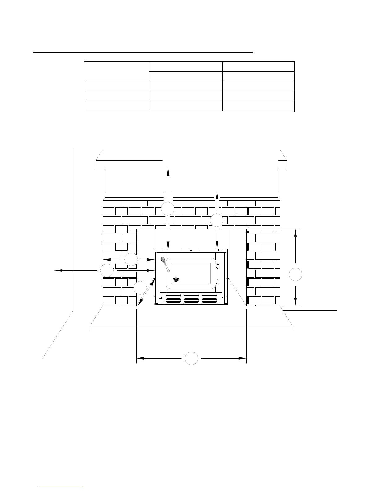
2.1 Clearances To Combustibles (Measured From Insert Body)
Sidewall (A) 13” (330 mm) 13” (330 mm)
Shelf (B) 22” (559 mm) 22” (559 mm)
Side mantle (C) 10” (254 mm) 10” (254 mm)
Top mantel (D) 29” (737 mm) 29” (737 mm)
XTD1.5-I XTD1.9-I
Table 2.1
CLEARANCES
COMBUSTIBLE SHELF
TOP MANTLE
D
B
SIDE MANTLE
A
C
F
H
ADJACENT SIDEWALL
G
Figure 2.1
Note: If side mantle protrudes more than 1.5” (38mm) in front of face of fireplace, then use
sidewall clearance.
7
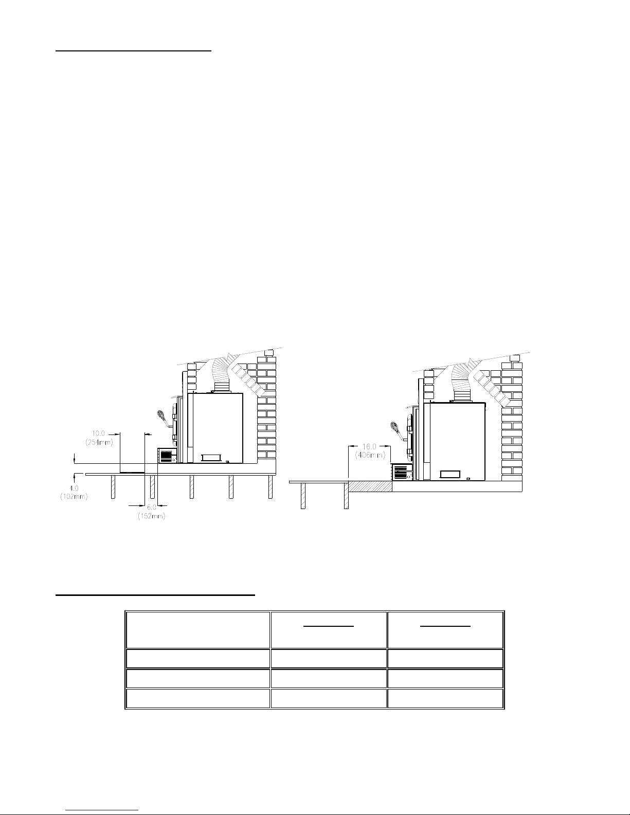
2.1.1 Hearth Requirements
If the non-combustible hearth is flush with the floor, then the hearth must be 16”/406mm
(18”/450mm in Canada) in front of the fan housing (see Figure 2.1.2). If the noncombustible hearth is a minimum of 4” (102mm) above the floor, then the hearth can be 6”
(152mm) out from the fan housing with a 10” (254mm) floor protection (sparks) extended
beyond the hearth (see Figure 2.1.1). The non-combustible hearth must be a minimum of 8”
(203mm) on each side of the unit (Canada & USA).
Convert specification to R-value:
k-factor is given with a required thickness (T) in inches: R=1/k x T
C-factor is given: R=1/C
Example:
If the floor protector is 4” brick with a C-factor of 1.25 over 1/8” mineral board with a k
factor of 0.29 the total R-value of the system is:
4” brick C=1.25, R=1/1.25=0.8
1/8” mineral board K=0.29, R=1/0.29 x 0.125=0.431
Total R = Rbrick + Rmineral = 0.8 + 0.431 = 1.231
Total R is greater than 1.0, the system is acceptable.
2.2 Suitable Fireplace Dimensions
Figure 2.1.1 Figure 2.1.2
Measurement for :
Opening Height (F) 21½” (546 mm) 24” (610 mm)
Opening Width (G) 29” (737 mm) 29” (737 mm)
Opening Depth (H) 14” (356 mm) 16.5” (420 mm)
XTD1.5-I
Minimum
Table 2.2
8
XTD1.9-I
Minimum
 Loading...