

Page 1

QUAD CV RECORDER
MANUAL
Version 1.00
FLAME
Page 2

Manual FLAME 4CVREC Version 1.00
Index
1. Short description ..................................................................... 3
2. Hardware / Connections ........................................................... 4
Connection to the modular system (Doepfer Bus) 4
Module frontpanel overview 5
3. Quick start ................................................................................ 6
First steps: Put in backup battery 6
First steps: POT-RECORDER 7
4. Operation .................................................................................. 8
Basic operations 8
Example: Source of track 1 = potentiometer 8
5. Functions .................................................................................. 9
SOURCE 9
ZOOM 9
RANGE (Offset) 10
RECORD 11
PUNCH IN/OUT RECORDING 12
PLAY MODE: LOOP, SINGLE, GATE, SCAN 13
PLAY funktions: SPEED, START, LENGHT 14
LINK (multitrack functions) 15
CLOCK - external synchronisation via Analog Clock 16
CLOCK - external synchronisation via MIDI Clock 17
Firmware update 18
Exchange backup battery 19
List of basic settings 20
6. Appendix .................................................................................. 21
2
Page 3

1. Short description
The module is a four-channel CV recorder/looper that records and plays back voltage curves
from very slow speeds to faster speeds by moving the controllers.
You can record control voltage courses from analogue sequencers, LFOs, envelope generators,
joysticks etc..
The input/output CV of each channel can range from -5v..+5v or 0..+9v.
SOURCE is the CV source of the track for the recordings. This can be the CV input, the potentiometer or both.
ZOOM is a two stage fine adjust function of the control ruler.
Synchronization via clock or MIDI and "punch-in" recordings are possible.
The output is a smoothed voltage without audible increments (algorithm with 16 bit resolution).
While the Clock/MIDI Synchronisation is used, they have two different levels (HARD/SOFT) for
the CV interpolation.
Independent of selected sync mode, the recording time per channel is up to one hour (such us
MIDI clock).
Function LINK: All four channels can be used individually or in groups of two or four tracks at
any one time (for multitrack or joystick recording).
There are different playback modes and several functions for the playback controls.
The different modes include: one-shot, triggered by a gate, a push-button or by MIDI-start/stop.
The sample can be looped as well.
Using the SCAN mode, the recorded sample can be scanned via CV input or the pot of the channel. It is possible to play manually the track velocity and direction (feasible effects: reverse, randomized, stuttering).
The start point, end point and the speed of playback or of the loop is set with the CVs or pot
(functions: START, LENGHT, SPEED).
The memory is non-volatile, as such the recordings and settings remain unchanged when the
modular system is powered down.
Software updates are possible via MIDI sysex dump.
MIDI adapter is included with the unit.
3
Page 4

4
Connection to the modular system (Doepfer bus)
+12v
ground
ground
ground
-12v
The module is delivered with a connected ribbon cable for the Doepfer bus. The red lead marks
-12 volt. Connecting the module please note the right polarity!
If the module is poled accidentally wrong safety diodes avoid the immediate destruction of the
module but further damages cannot be excepted. So please pay attention: Check the connection various times before switching on!
Advice: Please check the correct connection several times before switching-on the module!
Attention! Please avoid doing electrostatic voltages (don’t touch the pins of the chips or the
electronic). Please touch the modul frontpanel only for installation in your rack.
2. Hardware / Connections
Page 5
5
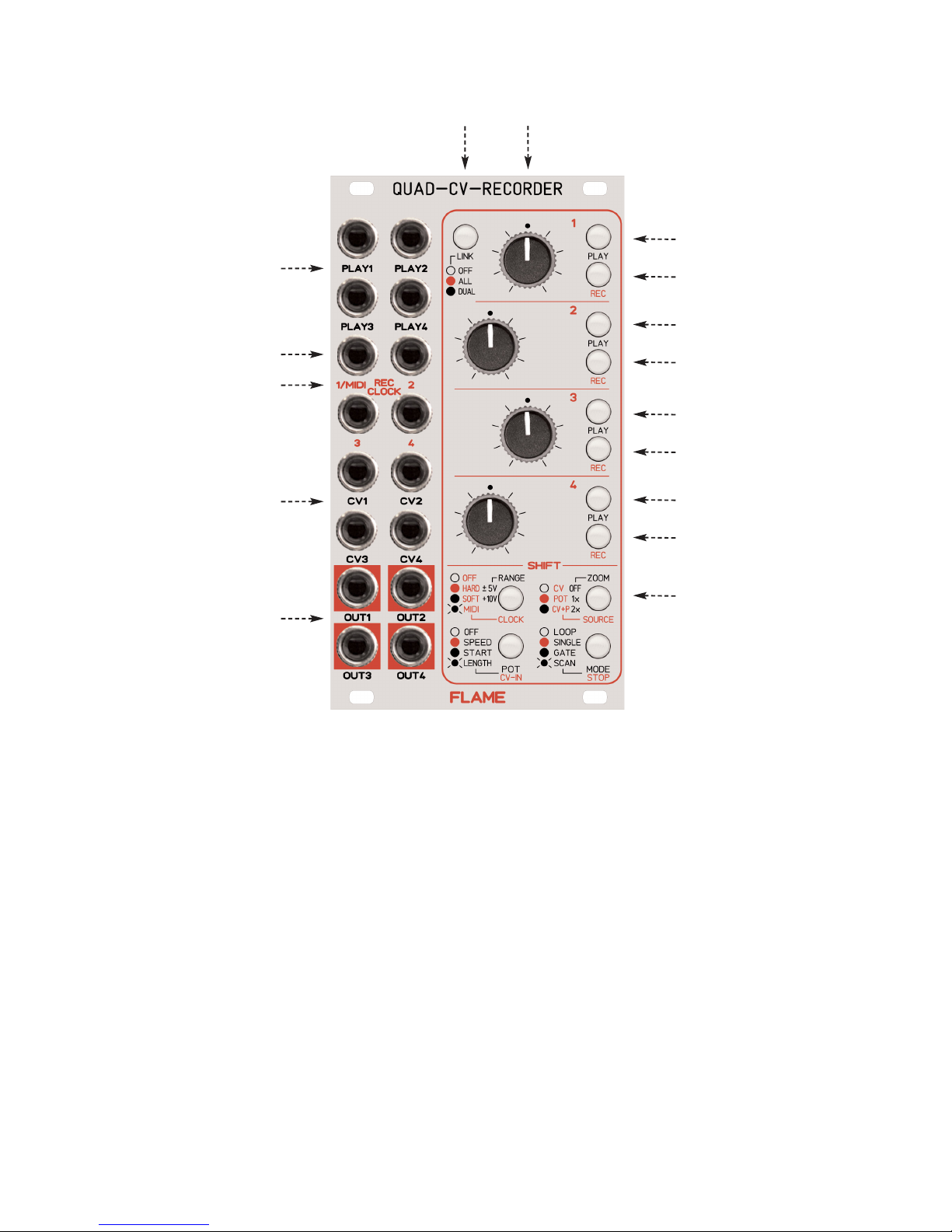
Module frontpanel overview
PLAY button track 1
Potentiometer tracks 1-4LINK push button
Gate/Trigger inputs
for PLAY tracks 1-4
POTENTIOMETER 1-4 Individual programable potentiometer tracks 1-4 either
as CV source during recording or
as controller pot during play back
INPUTS CV 1-4 Individual programable CV inputs tracks 1-4 with selected range: -5..+5v, 0..+9v
as CV source during recording or
as CV during play back
INPUTS PLAY 1-4 Gate/Trigger inputs PLAY (playback start/stop) tracks 1-4 : 0/+5v
INPUTS REC 1-4 Trigger inputs RECORD / CLOCK tracks 1-4 : 0/+5v
Additional option: Input REC-1 = MIDI-INPUT (via MIDI adapter)
OUTPUTS CV 1-4 CV outputs tracks 1-4 with selected range: -5..+5v, 0..+9v
SHIFT BUTTONS Shift buttons (functions) in combination with Play/Record buttons
SHIFT+PLAY --> black printed functions
SHIFT+RECORD --> red printed functions
LINK BUTTON Selector switch for LINK modes
RECORD button track 1
PLAY button track 2
RECORD button track 2
PLAY button track 3
RECORD button track 3
PLAY button track 4
RECORD button track 4
4 SHIFT buttons
CV inputs
for tracks 1-4
CV outputs
for tracks 1-4
Gate/Trigger inputs
for RECORD or CLOCK
tracks 1-4
MIDI input
Page 6

3. QUICK START
FIRST STEPS
1. Put in the backup battery before you start the module first time
Put in the memory-backup-battery! Please use the provided 3v lithium
backup battery (type CR2032) or a standard comparably battery.
Please note the correct polarity: Positive pole outwards!
After the first power-on the module starts automatically with the basic settings.
6
Page 7

FIRST STEPS
POT RECORDER
After the first startup you can use the module easily like a pot-recorder. You can record and play
back the movements of the ruler separately of each track.
Example Pot Recorder track 1 for control filter frequency:
1. Connect the output CV-1 with the CV input (filter frequency) of your
external filter module.
2. Set SOURCE of track1 to POT: While hold down the button SHIFT
SOURCE press the button REC-1 (as the case may be several
times) until the REC-1 LED is red.
3. Turn the ruler 1 in order to hear the filter.
4. Push the button REC-1 for setting the track in record standby
mode (blinking REC-1 LED red).
5. Push the button PLAY-1 for starting the recording
(PLAY-1 and REC-1 are constant red).
6. Turn the ruler over a period of time.
7. Push again the button PLAY-1 for stop the recording.
Now the playback begins automatically (PLAY-1 is constant green).
8. Stop the play back with buttons SHIFT STOP + REC-1.
The output holds on the last sample voltage. If you turn the pot,
then the output voltage switches to the voltage of the pot.
7
Page 8
4. OPERATION
8
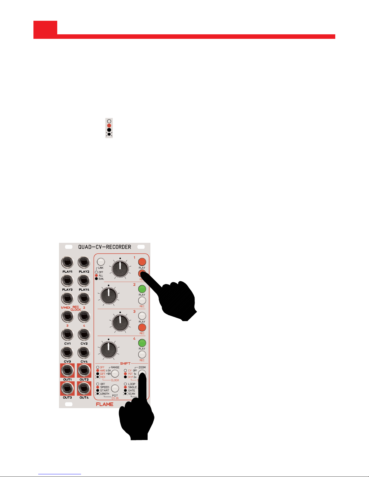
How you can change and display the settings:
Make settings by means of a combination of buttons SHIFT + PLAY or REC.
While you push down a button SHIFT the LEDs of buttons PLAY and REC display the settings
via the LED colors.
You find the color codes of the functions besides the SHIFT buttons.
Change the black functions with buttons SHIFT + PLAY.
Change the
red functions with buttons SHIFT + REC.
You can change the LINK modes directly with the button LINK.
Example:
Set the SOURCE of track 1 to POT :
While you hold down the button SHIFT “SOURCE/ZOOM” push the button REC-1 (as the case
may be several times) until the LED of button REC-1 is red.
1. while hold down
2. edit
LED aus
LED rot
LED grün
LED grün blinkend
ADVICE:
The memory is non-volatile, as
such, the recordings and settings remain unchanged when
the modular system is powered
down (only with included backup
battery.
Page 9

9
SOURCE
SOURCE is the CV source of the track for the recordings. This can be the CV input, the potentiometer or both.
If the track is stopped, then the output holds on the last sample voltage. If you move the pot,
then the output voltage switches to the voltage of the pot/input (SOURCE).
The CV output has the voltage of SOURCE if the track is in record standby (REC is blinking red)
and during the recording (PLAY+REC are constant red).
SOURCE can be set seperatly for each track and each LINK mode.
ZOOM
ZOOM is a two stage fine adjust function of the control ruler. A small range around the current
pot position is stretched over the complete pot range.
ZOOM is available only if the pot is used as CV source.
5. FUNCTIONS
POT
CV-Input
POT
+CV-Input
CV-out
Page 10

10
RANGE (OFFSET)
You can set the voltage range of each track to bipolar or unipolar:
RANGE can be:
bipolar: -5v ... +5v (calibrated)
unipolar: 0,1v ... +9v (calibrated)
Input and output of the track have the same RANGE setting.
It’s possible to reset the Range setting after recording.
Input voltages outside of the range are ignored.
RANGE +/-5v
(bipolar -5v..+5v)
RANGE +10v
(unipolar 0,1v..+9v)
POT OUT
-5v
+5v
-5v...+5v
CV-IN
-5v...+5v
0...+9v
CV-IN POT OUT
0v
+9v
0..+9v
Page 11

RECORD (externe CLOCK=OFF)
Before recording you have to stop the track and then you have to set the track in record standby mode. You can make it manually with the button REC or external via REC-input trigger.
If the track is in record standby mode the button REC is blinking red. If you wish to disable the
record standby mode, push the button REC again.
You start the recording either manually with the button PLAY or external via the PLAY-input trigger. Both buttons REC and PLAY are constant red.
You stop the recording either with pushing again the button PLAY or via the next PLAY-input trigger. The maximal recording time is 66 seconds (mode Clock=OFF). After the maximal time the
recording is stoped automatically and the play back begins.
EXAMPLE
Manually record an external CV with internal Clock (mode external CLOCK=OFF):
1. Before you begin set the track parameters CLOCK=OFF and SOURCE=CV.
(Use the button combinations CLOCK+REC and SOURCE+REC)
2. Push the button REC for setting the track in record standby mode
(blinking REC LED red).
3. Push the button PLAY to start the recording
(PLAY and REC are constant red).
4. Now the recording is on the run.
5. Push again the button PLAY to stop the recording.
Now the playback begins automatically (PLAY is constant green)
11
Page 12

PUNCH IN/OUT RECORDING
While the track is played you can manually overwrite parts of the track. The old parts of the track
are modified with the new recorded parts.
Please note: the punch-in/out procedure is irreversible.
You can use the punch in/out recording only manually via REC buttons!
Also you can use PUNCH IN/OUT recording with slower or faster SPEED.
12
PLAY
(play back of the original track)
PUNCH IN
push REC once only
(new record begins)
RECORD
(overwriting runs - old record
area is changed)
PUNCH OUT
push REC once again
(punch record is finished)
PLAY
(play back of the modified track)
Page 13

PLAY MODE
You have four different play back modes of the track:
LOOP
The play back runs endless (auto reset).
START: Button PLAY, Trigger PLAY-Input or MIDI-START-command
RESET: Button PLAY, Trigger PLAY-Input
STOP: Button STOP+REC or MIDI-STOP-command
SINGLE
The play back runs once only and is stoped by end of the track.
START: Button PLAY, Trigger PLAY-Input or MIDI-START-command
STOP: End of sample, Button STOP+REC or MIDI-STOP-command
GATE
While hold down button PLAY or the GATE-input is high the play back runs endless.
START: Pressed key PLAY or PLAY-Input=high oder MIDI-START-command
STOP: Unpressed key PLAY or PLAY-Input=off or MIDI-STOP-command
SCAN
Manually scan of the recorded sample with CV or movement of the pot. Internal or external
clock are disabled.
Voltage=zero (or the pot position min) are equivalent to the first value of the sample.
Voltage=max (or the pot position max) are equivalent to the last value of the sample.
It’s necessary to set the function of POT or CV-IN to SPEED !
The shorter the sample, the better the resolution of the play back.
13
Page 14
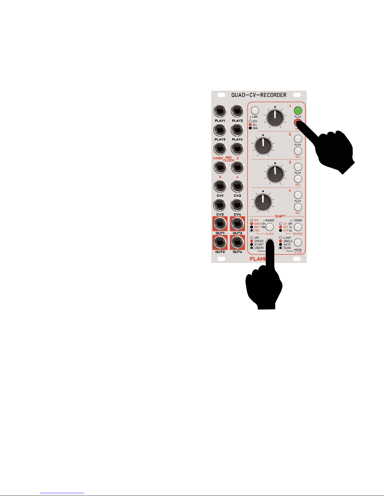
PLAY FUNCTIONS
While the track is played you can control the parameters SPEED, START, LENGHT with pot or
external CV input. You can set the functions separately for each track.
Please note: it’s not possible to set the same function to pot and CV input.
While you hold down the button SHIFT POT/CV
push the button PLAY or REC (of the channel).
For setup the pot use the keys SHIFT+PLAY
For setup the pot use the keys SHIFT+REC
OFF
Pot`s and/or CV inputs have no play functions
SPEED
.. is the speed of the play back.
The speed is not carried out with sample rate
modifications, but interpolation of the samples.
Therefore the output is a smoothed voltage
without audible increments especially if the
speed is slow.
if CLOCK=OFF (internal clock):
continuous control of the speed
if CLOCK=ON (HARD, SOFT, MIDI):
quantized control of the speed
(incremental duplets and triplets - for example half time oder double time)
if MODE=SCAN:
Not an automatically speed per clock. Using the SCAN mode, the recorded sample can be scanned via CV input or the pot of the channel
START
start position of the sample track
LENGHT
end position of the sample track
14
1. while hold down
2.
edit
example
track 1
Page 15

LINK
All four channels can be used individually or in groups of two or four tracks at any one time (for
multitrack or joystick recording).
Stepping the mode directly with the key LINK.
Please note: You can change the mode only in stop mode.
The settings of functions SOURCE, CV-IN/POT and CLOCK can be independent for all three
LINK modes OFF, ALL, DUAL.
OFF LINK LED off -->
LINK mode is off.
All four tracks work independently.
ALL LINK LED red -->
All four tracks are linked. Each PLAY/REC keys control all tracks similarly.
For external control you have to use the PLAY/REC inputs of channel 2
(The Inputs of channels 1,3 and 4 are inactive.)
This mode is used as multitrack recorder because you can record/play simultaneously all four
tracks. The functions SPEED, START and LENGHT control simultaneously all four tracks.
DUAL LINK LED green -->
The tracks 1+2 are linked and the tracks 3+4 are linked.
The PLAY/REC keys of track 1 or 2 control manually the tracks 1+2 similar.
But for external control you have to use only the PLAY/REC inputs of channel 2
(The Inputs of channel 1 are inactive.)
The PLAY/REC keys of track 3 or 4 control manually the tracks 3+4 similar.
But for external control you have to use only the PLAY/REC inputs of channel 4
(The Inputs of channel 3 are inactive.)
You can use the DUAL mode for joystick recordings (linked recording of x- and y- axis).
It’s possible to apply two joysticks independently.
The functions SPEED, START and LENGHT control simultaneously the linked tracks.
15
Page 16

CLOCK (external synchronization)
1. ANALOG CLOCK HARD/SOFT
Synchronization via analog clock (per REC/CLOCK inputs) or MIDI clock is possible.
One value is sampled per clock. The more clocks the merrier the resolution of the sample.
If you set the clock to “SOFT” then the output is a smoothed voltage without audible increments.
Sometimes it is usefull to set the output without smoothing (example for notes). In this case
choose the clock setting “HARD”.
While you hold down the button SHIFT CLOCK
push the button REC (of the channel) to set the
CLOCK (Sync modes).
HARD for direct voltage output (REC=rot)
SOFT for smoothed voltage output (REC=grün)
ATTENTION! If you use MIDI-Clock then also
automatically the clock mode of track 1 is activated
to MIDI clock mode because the REC input 1 is
also the MIDI input !
16
1. while hold down
2. edit
RECORD / PLAY with ANALOG CLOCK
Connect the clock out of the external analog sequencer with the REC/ClOCK input of the channel.
Connect the start/stop gate/trigger output of the
sequencer with the PLAY input of the channel.
1. Push the button REC for setting the track in record standby mode
(alternate blinking REC LED red-green, if analog clock is detected).
2. Start the external analog sequencer (sequencer send PLAY
trigger and the clocks) . Now the recording begins.
(Keys REC+PLAY of the track are red).
3. Stop the external analog sequencer.
The recording is finished. (REC+PLAY LED’s are off)
4. Start again the external analog sequencer to play back the track.
(PLAY LED is green)
5. Stop the external analog sequencer to stop the play back.
(PLAY LED is off)
Page 17

2. MIDI CLOCK HARD/SOFT
Synchronization via analog clock (per REC/CLOCK inputs) or MIDI clock are possible.
One value is sampled per one MIDI tick (96 values per measure).
If you set the clock to “SOFT” then the output is a smoothed voltage without audible increments.
Sometimes if desired to set the output without smoothing (example for notes). In this case choose the clock setting “HARD”.
While you hold down the button SHIFT CLOCK
push the button REC (of the channel) to set the
CLOCK (Sync modes).
MIDI (SOFT) for direct voltage output (REC is blinking green)
MIDI (HARD) for smoothed voltage output (REC is blinking red)
ADVICE: There are printed only ONE “blinking MIDI” symbol on the front panel.
But its possible to configure booth MIDI-Sync-Modes “HARD” and “SOFT” !
ATTENTION! If you use MIDI-Clock then also automatically the clock mode of track 1 is activa-
ted to MIDI clock mode because the REC input 1 is also the MIDI input !
17
RECORD / PLAY with external MIDI CLOCK
Connect the MIDI OUT of you external sequencer with the MIDI IN of the module (CLOCK input
of channel 1). Therefore you have to use the provided MIDI adapter accessory.
1. Push the button REC for setting the track in record standby
mode (blinking REC LED red).
2. Start the external MIDI sequencer.
(The sequencer sends MIDI start command and MIDI clocks) .
Now the recording begins. (Keys REC+PLAY of the track are red).
3. Stop the external MIDI sequencer.
Now the recording is finished. (Keys REC+PLAY of the track are off)
4. Start again the external MIDI sequencer.
(The sequencer sends MIDI start command and MIDI clocks) .
Now the play back begins. (Key PLAY of the track is green).
5. Stop the external MIDI sequencer to stop the play back.
(PLAY LED is off)
Page 18

FIRMWARE UPDATE
You can easily update the firmware with a MIDI sysex dump. To do so, use a MIDI-sysex-dumploader for example the freeware MIDI-OX or Electron C6 (win or mac).
1. Load the firmware sysex file to your computer.
2. Connect the MIDI interface of the computer with the MIDI input of the modul
(jack REC-1/MIDI). Therefore you have to use the provided MIDI adapter accessory.
3. Hold down both keys LINK and STOP while you power on the module.
The key LINK is blinking red.
4. Now send the Sysex firmware file to the module. While the update runs you can see the
progress indicator (green PLAY LED’s and red REC LED’s bar). The upload during time is
for instance 1,5 minutes.
5. If no error message is displayed the update is succesfull finished.
The module reboots automatically
ERROR CODES
PLAY 1 LED blinking green Wrong SysexID
PLAY 1 LED blinking red Packet Checksum Error
PLAY 2 LED blinking green Firmware Checksum Error
PLAY 2 LED blinking red Flash Error
PLAY 3 LED blinking green Timeout
PLAY 3 LED blinking red Interface Check Failed
ADVICE:
Sometimes it’s necessary to set the parameter “Delay” or “Timeout” to higher values (such as
80ms) from your used dumploader software.
18
Page 19

19
EXCHANGE BACKUP BATTERY
Please use a standard 3v lithium backup battery (type CR2032).
Please note the correct polarity: Positive pole outwards!
ADVICE:
You can conserve your data if the old battery is not complete empty. In this case exchange the
battery while the module is power on.
Otherwise the module starts automatically with the basic settings and clear the memory.
Page 20

20
LIST OF BASIC SETTINGS
Function Track 1 Track 2 Track 3 Track 4
ZOOM OFF OFF OFF OFF
SOURCE OFF OFF OFF OFF
RANGE +/-5v +/-5v +/-5v +/-5v
CLOCK OFF OFF OFF OFF
POT OFF OFF OFF OFF
CV-IN OFF OFF OFF OFF
MODE LOOP LOOP LOOP LOOP
LINK OFF
The basic setting of SOURCE from modes LINK ALL and DUAL for all tracks is POT.
Page 21

5. Appendix
Technical details
Current consumption: ca. +160mA / -50mA
Size: Euro format 3U / 14HP 70,5 x 128,5 x 42mm
Warrenty
Beginning from the date of purchase a 2-year warranty is guaranteed for this device in case of
any manufacturing errors or other functional deficiencies during runtime.The warranty does not
apply in case of:
- damage caused by misuse
- mechanical damage arising from careless treatment (dropping, vigorous shaking, mishandling, etc)
- damage caused by liquids penetrating the device
- heat damage caused by overexposure to sunlight or heating
- electric damage caused by improper connecting
(wrong power supply/ jacks/ MIDI connections/ voltage problems).
If you have any complaints please contact your dealer or send an e-mail to:
service@flame.fortschritt-musik.de
Terms of production
conformity: CE, RoHS, UL
Disposal
The device is produced with RoHS-conformity (subject to the regulations of the European Union)
and is free of hazardous substances (like mercury, plumb, cadmium and hexavalent chrome).
But electronical scrap is hazardous waste. Please don't add this to consumer waste. For an
environment friendly disposal of waste please contact your distributor or specialist dealer.
Support
Updated and additional informations, updates, downloads and more see:
http://flame.fortschritt-musik.de
Acknowledgment
For help and assistance big thanks to: Alex4 Berlin, Shawn Cleary (Analogue haven), Robert
Junge, Anne-Kathrin Metzler, Lena Bünger, Baron, Ebotronix and FX Gueule Cassée.
Hardware + Concept: Per Salzwedel, Sebastian Preller
Software: Sebastian Preller
21
 Loading...