

Page 1

Shut-off poppet valve,
Ň
designed to operate with gas detectors
2/2 way type ZB
Class
A - DN20¸DN65
klasa B
B - DN80 i DN100
Group 1
Diameters range DN
Media
threaded connection
Rp 3/4 ¸ Rp 2 1/2 (DN20 ¸ DN65) DN50 ¸ DN100
gas fuels (gases as per PN-EN 437)
FEATURES:
poppet valve
!
! simple design
! unidirectional, uniform flow
! triggered elecromagneticly
! available with two types of solenoid triggers:
WE (12V DC) or EZB-12,6G (230V AC)
! low weight (mass)
! bistable - in lack of voltage condition the valve could stay in one of stable
position: open or close.
Control voltage is necessary or valve closing only.
! opened only manualy (“memory” function)
! closed with electrical impulse
! has the option for manual closing with botton
! permanent strainer built-in
! adapted for external application
! conforms to
!
meets applicabe requirments of Regulation (UE) 2016/426 (GAR) from
PN-EN 161:2011+A3:2013
9 march 2016 y. and Directives UE:
2014/35/UE (LVD); 2014/30/UE (EMC)
APPLICATION:
in Gas Safety Systems installed: gas boiler rooms, industrial facilities,
!
public utility buidings, domestic installations (i.e.one family houses and
multi-family houses, farmsteads, private use recreational buildings),
reducing -measuring stations, biogas plants, etc. itp. - as an actuator
that surely and effectively cuts off the gas supply to faulty installations
when a gas presence is detected in supervised by System compartments
! in gas installations supplied in conformance with appropriate regulations
from low pressure gas grid
! additionally valve can be used as manual stopcock, however it can not act
as gas installation main stopcock
! together with gas detection system, valve can perform a function of lock-
up for devices that burn gas fuels and are intended for use inside the
buildings and utility compartments. Such a lock-up prevents from
accumulation of burning gas in mentioned buildings and compartments
TECHNICAL DATA
Valve
maximum operating pressure......... P = 0,25 bar
safe static pressure ........................ P = 5 bar
closing time ................................... < 1s
ambient and media temperature ... -25 C ¸ 60 C
pipe threaded connection .............. Rp - internal straight thread
pipe flanged connection ................
mounting direction ......................... any
Solenoid trigger
trigger type..................................... WE EZB-12,6G
control voltage....................... ........ 12V DC 230V AC
voltage tolerance ........................... -15%; +10%
power consumption........................ 26 W 46 VA
coil resistance ............................... 5,5 W 134 W
safety class ................................... III I (earthing)
impulse minimum time duration..... 0,2s -0,3s
(necessary for closing the valve)
operation type ............................... S1 continuous 100%
ambient temperature .................... -30 C ¸ 60 C
electrical connection ..................... tri-contact terminal block
degree of protection (acc. PN-EN 60529) IP65
design (integrated) ............................ resin-molded coil
MAX
S
o o
compliant with PN-EN 10226
keeps compatibility of flange
connection dimensions [PN16, 01, B]
in acc. with PN-EN 1092-1
o o
flanged connection
1015
Schematic symbol
A
P
ELECTRICAL TERMINATION
coil connection
12
plug-in socket
21
The plug can be fixed in 3
positions towards the socket
(each 90 )
AC
2
1
L
N
PE
max
3x1,5
Conductor wires polarization-indifferent (apart from PE);
recommended - as on figure
Connection wire size depends on the distance to
control module - see Service Manual of applied
control module.
Size and allowable lenght could be also
determined assuming as admissible10% voltage
drop on conductor (calculated from rated voltage
12 V)
PG11
O
AC, DC
1
DC
2
1
Mp
max
2
P
3x1,5
page 1/4ZB - data sheet release 02/2019/KK
Page 2
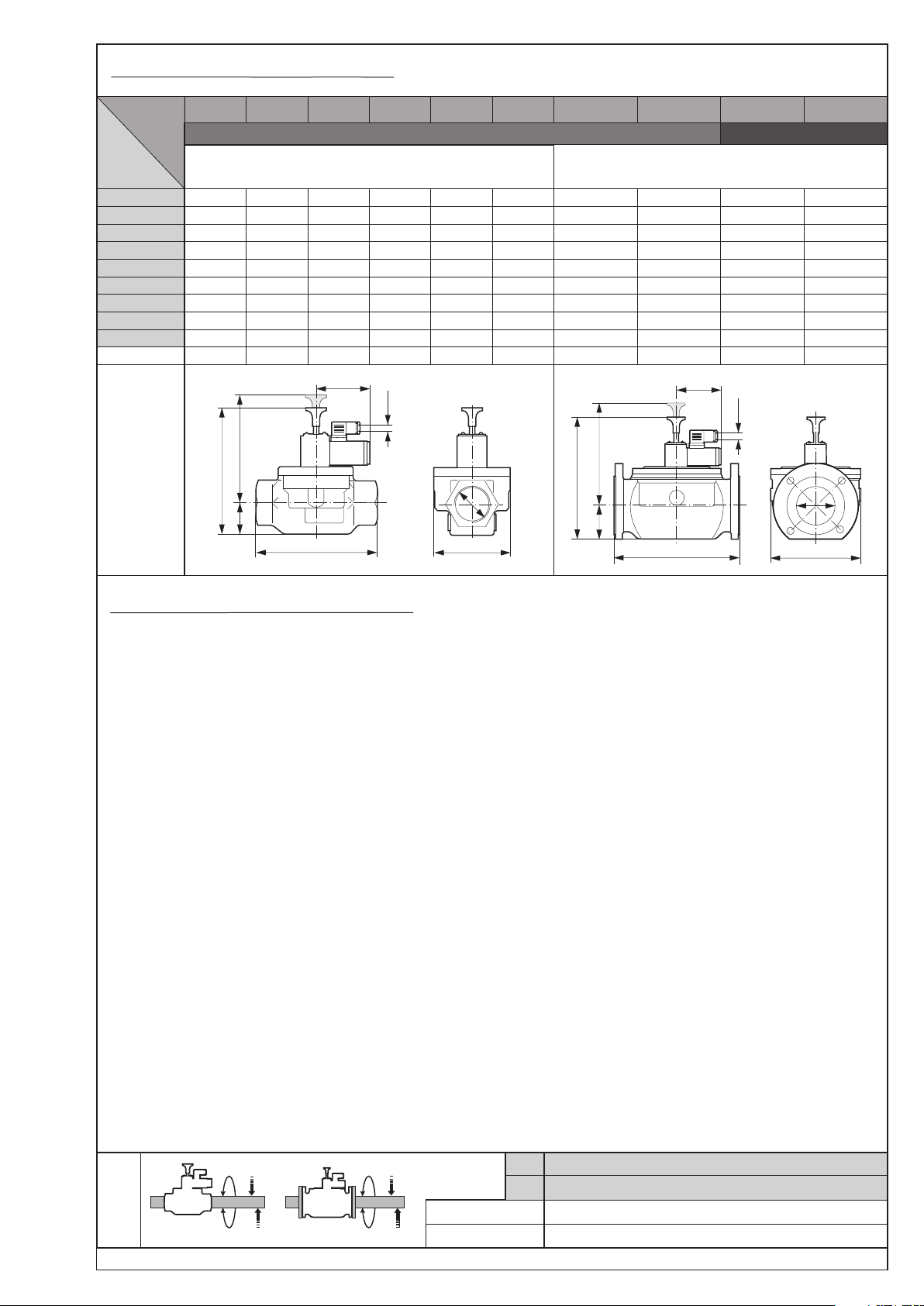
OVERALL DIMENSIONS (mm), WEIGHT (kg)
DN
Rp
A
B
(1)
C
E
L
P
Pg
Weight
ZB-20Type
ZB-25 ZB-32 ZB-40 ZB-50 ZB-65 ZB-50k ZB-65k ZB-80k ZB-100k
valves with threaded connection
(internal straight thread in acc. with PN-EN 10226)
20
3/4
127
22
112
77
105
92
11
1,20
A
25 32 40 50 65 50 65 80 100
1 1 1/4 1 1/2 2 2 1/2
137 155 180 188 218 225 243 307 318
28 37 48 40 61 78 83 94 103
116 126 143 158 170 157 171 231 239
79 100 112 142 170 165 185 200 222
115 144 178 193 240 230 270 310 350
92 92 92 92 92
11 11 11 11 11 11
1,35 1,96 2,62 3,18 4,81
P
Pg
C
B
L
valve class A
Rp
E
valve class B
valves with flanged connection [PN16, 01, B]
(conforms to PN-EN 1092-1)
92 92 95 95
11 11 11
4,06 5,82 9,80 11,82
P
Pg
C
A
DN
B
L
E
INSTALLATION - basic assembly requirments:
! valve can be installed:
Ř outside the buildings - in the junction box protecting
against direct influence of atmospheric factors
Attention! Valve is not waterproof!!!
It should be installed in such a box and in such a
way that it is completely protected against
dripping water during rain and snowfall.
Ř inside the buildings
! install downstream the main tap, upstream or downstream
the gas meter (according to the gas flow arrow on the valve)
! it is necessary to anticipate and take into account the
pressure surplus that may occure at the valve inlet in case of
failure to components in the system located upstream the
valve
! mounting position - any
! direct contact of the valve with wall, ground, etc. is
unacceptable; keep the minimum distance - about 1 cm
! location of the valve should be selected so as to ensure free
access needed to its operation (for persons authorized to do
so)
! attention should be paid so that after valve installation there
is enough space left (maneuvering area) for ease coil
replacemet
! ensure proper rigidity of the installation in the place where
the valve is installed (Group 1 valve).
This can be achieved by using rigid supports to the bending
and torsional stress exerted by the piping system in the
installation (eg due to the lack of alignment of the of the
pipeline at the inlet and outlet of the valve)
! maximum moments: turning T and bending M
cannot exceed the values given in TABLE 1
MAX MAX
! ensure that valve is mounted rigidly so as to avoid any
vibration
in valves with threaded connections pipe should be screw in
!
that way so that 10 second torque not exceed values of
T given in TABLE 1
MAX
use appropriate thread sealant to esure tightness of the
!
connections
! tighten the flange screws crosswise Attention: maximum
torque of 50 Nm (~5 kGm)
! a strainer which protects from mechanical impurities should
be fitted upstream the valve in the gas installation.
Maximum dimension of strainer openings should not
exceed 0,2 mm
! valve’s assembly should be finalized with carrying out an
leaktightness test of installation including ZB valve using
compressed air or inert gas (oxygen use is forbidden)
Test pressure cannot exceed P = 5 bar
! during operation valve
S
- cannot be exposed to dilatation nor dynamic forces
- need to have ensured correct operating temperature
(ambient and media)
- should be protected against strong dustiness and
water flooding
TABLE 1
DN
20
25
32
40
50
65
80
400
780
100
400
950
page 2/4ZB - data sheet release 02/2019/KK
M
MAX
M
T
MAX
MAX
M
MAX
Rp
3/4
T
MAX
M
T
MAX
MAX
M
MAX
Ł
[Nm] t 10s
[Nm] t Ł10s
85
90
1
125
160
1 1/4
160
260
1 1/2
200
350
2
250
520
2 1/2
325
630
Page 3

CONSTRUCTION
valve manual open hand grip
1.
pilot sleeve
2.
3.
poppet pin
4.
slide rings
5.
pull spring
6.
sealing ring (o-ring)
7.
bonnet
8.
sealing ring (o-ring)
9.
pressing spring
10.
filter
11.
poppet
12.
poppet gasket
13.
valve seat
14.
valve body
15.
fastening screw
16.
plug-in socket
17.
impedance coil Pg11
18.
power supply socket
19.
trigger movable core
20.
valve manual close button
21.
solenoid trigger
22.
interlock ball
23.
seating stud
24.
plug G1/8 lub G1/4
25.
limit switch for example K01/1type from DUNGS
26.
impedance coil Pg11
27.
obique bush
28.
limit switch push rod
29.
pushing ball
1
2
3
4
5
6
7
8
9
10
15
16
17
18
19
20
21
22
23
PP A
11
12
13
14
Valve head* position sensor
(valve closing)
Switchning function
25 26 27 28 29 3
1
24
3
2
F
Constructional materials
valve body aluminium alloy
poppet pin stainless steel
pilot sleeve aluminium alloy
springs galvanized or
stainless steel
poppet body aluminium alloy
poppet gasket NBR (nitrile-butadiene rubber)
valve seat aluminium alloy
sealings NBR (nitrile-butadiene rubber)
slide rings PTFE
filter stainless steel - filter gauze
solenoid coil copper
(*) - valve head: movable part of valve which shuts-off gas fow
page 3/4ZB - data sheet release 02/2019/KK
Page 4

Dp
FLOW CHARACTERISTIC
[mbar]
80
60
2 3 4 10865 20 30 40
1
2 3 4 10865
Base conditions
O
+15 C
1,013 bar
dry
ZB - 20
ZB - 25
ZB - 32
ZB - 40
20 30 40 100806050 200 300 400 800600
air dv =1
ZB - 50
ZB - 65
ZB - 80
ZB - 100
Q [m /h]
3
3 4 865
2 3 4 10865 20 30 40 100806050 200 300 400 600
10
20 30 40 100806050
natural gas (methane) dv =0,65
propane-butane dv =1,56
200 300 400 800600
ACCESSORIES - options (available upon request)
! plugs G1/8 or G1/4 (position 24) with gaskets
Note that standard version does not have holes for
above plugs.
! counterflages with connector pipe (for valves with flanged
connection)
! stub pipe for inlet and/or outlet pressure measurment
(Ć 9, G1/8 lub G1/4 together with gaskets)
- used alternatively with plugs
! gas pressure sensor (at the inlet anr/or outlet of a valve)
Pressure sensors are assembled as marked on figure,
position 24
! valve head position sensor (position 25) from DUNGS type
K01/1
! plug with voltage presence indicator
! colour
ORDERING
Necessary information for ZEG valve order:
! valve type
! control voltage
! possible option and accessories
Example:
ZB-32/12V DC
it means:valve with threaded connection DN32
control voltage DC 12V
standard design
3
Q [m /h]
3
Q [m /h]
FLAMA-GAZ ELEKTROZAWORY S.C.
43-418 Pogwizdów k/Cieszyna, ul. Szkolna 3
phone +48 33 856-85-70, fax +48 33 856-85-62, www.flamagaz.com, e-mail: firma@flamagaz.com
release 02/2019/KK
Modification without prior notice of technical specification reserved
page 4/4ZB - data sheet
 Loading...