

FlaktWoods STRA-14 Installation And Maintenance Manual

STRA-14 Room controller. Installation and maintenance manual.
Fläkt Woods 8710 GB 2016.09.08
1 (12)
Specifications are subject of alteration without further notice.
STRA-14 for chilled beams
STRA-14 is the room controller for the motorised energy control
(MEC) and constant air volume chilled beams
It is possible to set different parameter values in a parameter menu
in the display, using the buttons on the controller. You change
parameter values with the INCREASE and DECREASE buttons and
confirm changes with the Function button.
Technical data
Supply voltage 18...30 V AC, 50...60 Hz
Internal consumption 2.5 VA
Ambient temperature 0...50°C
Storage temperature -20...+70°C
Ambient humidity Max 90% RH
Protection class IP20
Communication RS485 (EXOline or Modbus) with automatic detection/change-over
Modbus - Bacnet - MSTP 8 bits, 1 or 2 stop bits. Odd, even (FS) or no parity.
Communication speed 9600 bps (not changeable)
Built-in temperature sensor NTC type, measuring range 0...50°C, accuracy +/-0.5°C at 15...30°C
Material, casing Polycarbonate, PC
Weight 110 g
This product conforms with the requirements of European EMC standards CENELEC EN 61000-6-1 and EN
61000-6-3, and the requirements of European LVD standard IEC 60 730-1. It carries the CE mark.
Inputs
External room sensor PT1000-sensor, 0…50°C. Suitable sensor is Fläkt Woods STRZ-05
Occupancy detector Closing potential-free contact. Suitable occupancy detector is Fläkt Woods STRZ-09.
Condensation detector alt.
window contact
Fläkt Woods condensation detector STRZ-16 alt. window contact STRZ-38 resp.
potential-free contact
CO 2 sensor
STRZ-18 (0-10V).
Outputs
Forced ventilation 24 V AC actuator, max 0.5 A
Valve actuator alt. thermal
actuator
2 outputs
Valve actuator 0…10 V DC, max 5 mA
Thermal actuator 24 V AC, max 2.0 A
Control Heating or cooling
Actuator exercise FS = 23 hours interval
Terminal blocks So-called lift type for cable cross-section 2.1 mm2
STRA-14 Room controller. Installation and maintenance manual.
Fläkt Woods 8710 GB 2016.09.08
2 (12)
Specifications are subject of alteration without further notice.
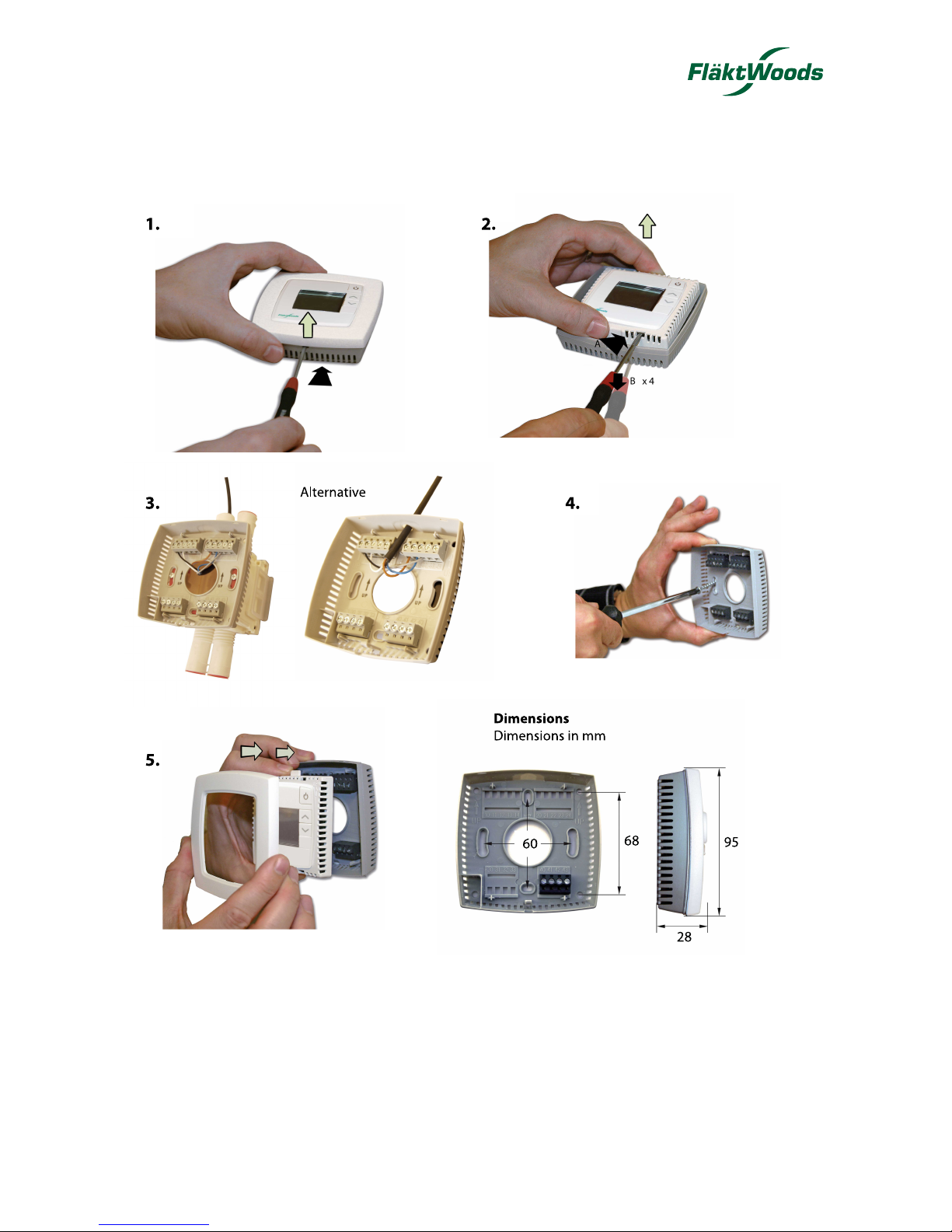
Installation instructions
Ensure that the installation complies with local safety regulations. Information about commissioning of the product can
be found in the manual ”STRA Manual”, which is available for download from www.flaktwoods.com.
STRA-14 Room controller. Installation and maintenance manual.
Fläkt Woods 8710 GB 2016.09.08
3 (12)
Specifications are subject of alteration without further notice.
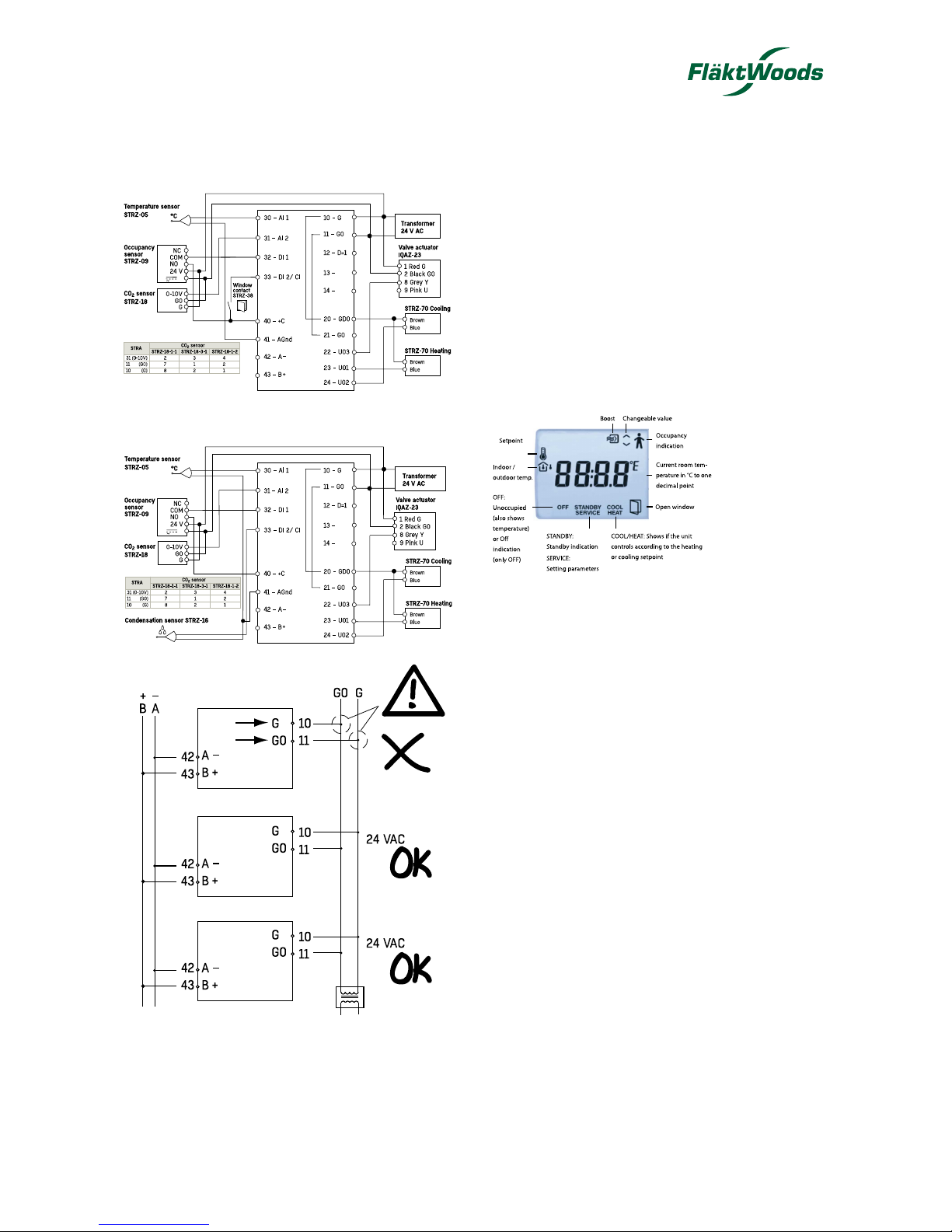
Wiring diagrams
Connection diagram for STRZ-05, STRZ-18, STRZ-09,
STRZ-70, IQAZ-23 and window contact STRZ-38
Connection diagram for STRZ-05, STRZ-18, STRZ-09,
STRZ-70, IQAZ-23 and condensation sensor STRZ-16
Controller handling
In Occupied mode, the controller operates from a heating
setpoint (FS = 22°C), or a cooling setpoint (FS = 24°C) that
can be changed using the INCREASE and DECREASE
buttons.
Pressing on INCREASE increases the current setpoint by
0.5°C with each press up to the max. limit (FS = +3°C).
Pressing on DECREASE decreases the current setpoint by
0.5°C with each press down to the min. limit (FS = -3°C).
Switching between heating and cooling setpoints is done
automatically in the controller depending on the heating
and cooling requirement.
Display handling
The display has the following indications:
Function button
By pressing the Function button for less than 5 seconds
when the controller STRA-14 is in the preset operating
mode (parameter 45, F5 = 3 = Occupied), the controller
changes the operating mode to Boost. If you press the
button for less than 5 seconds when the controller is in
Boost, it changes operating mode to the preset operating
mode.
When the Function button is held pressed down for more
than 5 seconds, the controller changes operating mode
to ”Unoccupied”, regardless of the current operating
mode. If you press the button for less than 5 seconds in
Unoccupied mode, the controller returns to Boost (for
60 minutes, which is a preset time that can be changed
though adjusting parameter 12).
Operating modes for chilled beams STELLA,
WEGA and NOVA
• Bypass = Boost mode
• Occupied = Normal mode
• Unoccupied = Energy saving mode

STRA-14 Room controller. Installation and maintenance manual.
Fläkt Woods 8710 GB 2016.09.08
4 (12)
Specifications are subject of alteration without further notice.
Wiring
STRA-14 has been constructed to be as compact as possible. Therefore, the controller’s communication input is not
galvanically separated from the supply voltage. This means that it is important to keep G and G0 in order, as well as the
communication input’s A and B.
All units that share the same transformer and communication loop must use the same transformer-pole for G (terminal
10) and G0 (terminal 11). On the communication loop the A-terminal (terminal 42) should only be connected to another
A-terminal and the B-terminal (terminal 43) to another B-terminal. Otherwise, there is great danger of short-circuit with
damaged components as a result.
Terminal Designation Operation
10 G Supply voltage 24 V AC
11 G0 Supply voltage 0 V
12 - 14 No function.
20 GDO 24 V AC out common for DO. Internally connected to terminal 10, G.
21 G0 0 V common for UO. Internally connected to terminal 11, G0.
22 UO3
Control output ventilation.
3 put analog (FS). The valve actuator’s 0…10 V control signal terminal is connected to terminal 22 and its supply
terminals to terminals 10 and 11. Make sure that the reference pole G0 is connected to the correct terminal on
the actuator.
23 UO1
Control of heating.
For 0...10 V DC valve actuator, max 5 mA. The valve actuator’s 0…10 V control signal terminal is connected to
terminal 23 and its supply terminals to terminals 10 and 11. Make sure that the reference pole G0 is connected
to the correct terminal on the actuator.
alternative
For 24 V AC thermal actuator, max 2,0 A (FS). The thermal actuator is connected between terminals 23 and 20,
GDO.
24 UO2
Control output cooling.
For 0...10 V DC valve actuator, max 5 mA. The valve actuator’s 0…10 V control signal terminal is connected to
terminal 24 and its supply terminals to terminals 10 and 11. Make sure that the reference pole G0 is connected
to the correct terminal on the actuator.
alternative
For 24 V AC thermal actuator, max 2,0 A (FS). The thermal actuator is connected between terminals 24 and 20,
GDO.
30 AI1
For external room sensor, PT1000. Measuring range 0...50°C. Sensor is connected between terminals 30 and
41, AGnd.
31 AI2
For 0-10V CO 2 sensor input.
32 DI1
Occupancy detector. A potential-free contact is connected between terminals 32 and 40, +C. Closed contact
corresponds to occupancy.
See also section Occupancy detector in the chapter Operating modes.
33 DI2/CI
Fläkt Woods condensation detector STRZ-16 (FS). The sensor is connected between terminals 33 and 41, AGnd.
alternative
Window contact (DI). A potential-free contact is connected between terminals 33 and 40, +C. Closed contact
indicates closed window.
40 +C 24 V DC out common for DI and UI (with digital function)
41 AGnd Analogue ground, reference for AI and UI (with analogue function)
42 A RS485-communication A 43 B RS485-communication B +
 Loading...