

flakt woods STRA-07 R Installation And Maintenance Manual

STRA-07 Room Controller. Installation and maintenance manual.
Fläkt Woods 8713 GB 2014.04 1
Specifications are subject of alteration without further notice.
Content STRA-07 for Fancoils
Installation preparations................................2
Controller/Display handling.........................5
Technical data..................................................5
Installation.......................................................6
Configuration..................................................6
Operating modes............................................7
Activation operating modes.........................7
Control states..................................................8
Actuators.........................................................9
Fan control.......................................................9
Forced ventilation/Condensation detector/
Frost protection..............................................10
Parameter settings.........................................10
STRA-07 Room Controller. Installation and maintenance manual.
Fläkt Woods 8713 GB 2014.04 2
Specifications are subject of alteration without further notice.
STRA-07 for Fancoils
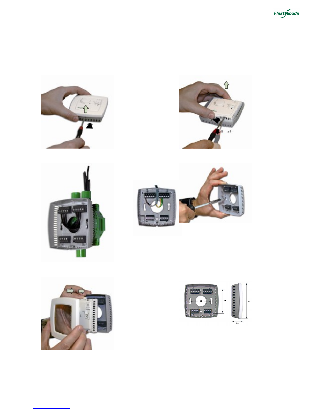
Installation instruction
Ensure that the installation complies with local safety regulations. Information about commissioning of the product can
be found in the manual ”STRA Manual”, which is available for download from www.flaktwoods.com.
1.
2.
3.
alt.
4.
5.
Dimensions
Dimensions in mm
STRA-07 Room Controller. Installation and maintenance manual.
STRA-07 for Fancoils
Fläkt Woods 8713 GB 2014.04 3
Specifications are subject of alteration without further notice.
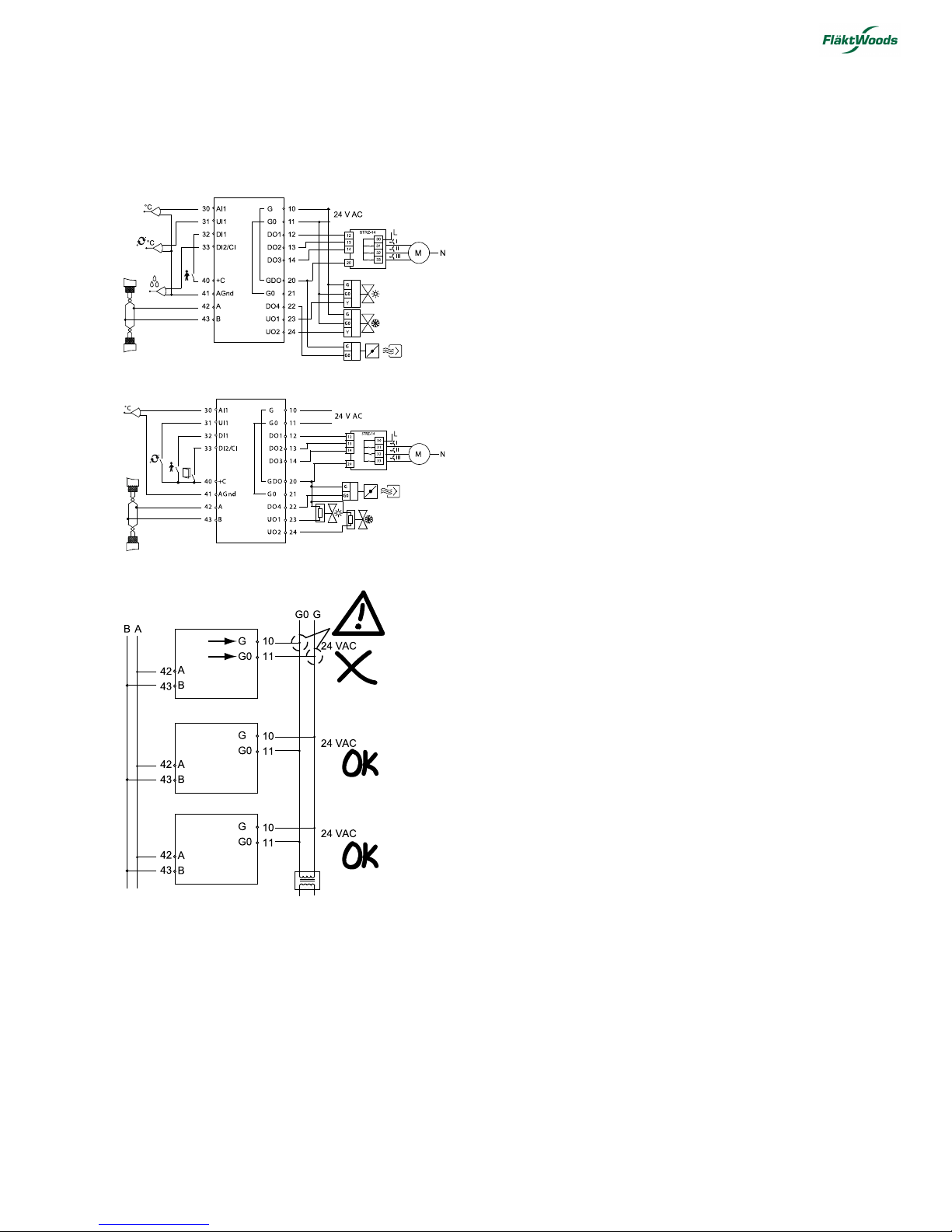
Wiring
STRA-07 has been constructed to be as compact as
possible. Therefore, the controller’s communication input
is not galvanically separated from the supply voltage.
This means that it is important to keep G and G0 in order,
as well as the communication input’s A and B.
All units that share the same transformer and
communication loop must use the same transformerpole for G (terminal 10) and G0 (terminal 11). On the
communication loop the A-terminal (terminal 42) should
only be connected to another A-terminal and the Bterminal (terminal 43) to another B-terminal. Otherwise,
there is great danger of short-circuit with damaged
components as a result.
Inputs
AI PT1000-sensor, 0...50°C, accuracy +/- 0.1°C
UI AI: PT1000-sensor, 0...100°C, accuracy +/- 0.2°C or
DI: see DI below
CI Fläkt Woods’s condensation detector, STRZ-16
DI Closing potential-free contact connected to +C in
one end
Outputs
DO 24 V AC, max 0,5 A
UO DO:24 V AC, max 2.0 A or AO:0.5...10 V DC, max
5 mA +C, power output for DI only...24 V DC,
max 10mA, short circuit protected

STRA-07 Room Controller. Installation and maintenance manual.
Fläkt Woods 8713 GB 2014.04 4
Specifications are subject of alteration without further notice.
Terminal Designation Operation
10 G Supply voltage 24 V AC
11 G0 Supply voltage 0 V
12 D01 For forced ventilation, low speed. 24 V AC output, max 0,5 A. 24 V AC actuator is connected between t erminal 12
and terminal 20, GDO.
13 DO2 For forced ventilation, average speed. 24 V AC output, max 0,5 A. 24 V AC actuator is connected between terminal
13 and terminal 20, GDO.
14 D03 For forced ventilation, high speed. 24 V AC output, max 0,5 A. 24 V AC actuator is connected between t erminal 13
and terminal 20, GDO
20 GDO 24 V AC out common for DO. Internally connected to terminal 10, G.
21 G0 0 V common for UO. Internally connected to t erminal 11, G0.
22 D04 For forced ventilation, 24 V AC output, max 0,5 A. 24 V AC actuator is connected between t erminal 22 and terminal
20, GDO
23 UO1 Control of heating (FS) or cooling via change-over.
For 0...10 V DC valve actuator, max 5 mA (FS). The valve actuator’s 0…10 V control signal terminal is connected to
terminal 23 and its supply terminals to t erminals 10 and 11. Make sure that the reference pole G0 is connect ed to
the correct terminal on the actuator.
alternative
For 24 V AC thermal actuator, max 2,0 A. The thermal actuator is connected between terminals 23 and 20, GDO.
On the display, go into the parameter menu and change parameter 20 to thermal actuator.
24 UO2 Control output heating or cooling (FS).
For 0...10 V DC valve actuator, max 5 mA (FS). The valve actuator’s 0…10 V control signal terminal is connected to
terminal 24 and its supply terminals to t erminals 10 and 11. Make sure that the reference pole G0 is connect ed to
the correct terminal on the actuator.
alternative
For 24 V AC thermal actuator, max 2,0 A. The thermal actuator is connected between terminals 24 and 20, GDO.
On the display, go into the parameter menu and change parameter 20 to thermal actuator.
30 AI1 For external room sensor, PT1000. Measuring range 0...50°C. Sensor is connected between terminals 30 and 41,
AGnd.
31 UI1 For switching between heating and cooling on a two-pipe system (Change-over). PT1000-sensor is connected
between terminals 31 and 41, AGnd. Measuring range: 0...100°C. alternatively For potential-free contact. A pot ential-
free contact is connected between terminals 31 and 40, +C.
32 DI1 Occupancy detector. A potential-free cont act is connected between terminals 32 and 40, +C. Closed contact
corresponds to occupancy.
See also section Occupancy detector in the section Operating modes.
33 DI2/CI Fläkt Woods’s condensation detector, STRZ-16 (FS). The sensor is connected between ter minals 33 and 41, AGnd.
alternative
Window contact (DI). A potential-free cont act is connected between terminals 33 and 40, +C. Closed contact
indicates closed window.
40 +C 24 V DC out common for DI and UI (with digital function)
41 AGnd Analogue ground, reference for AI and UI (with analogue function)
42 A RS-485-Communication
43 B RS-485-Communication
STRA-07 Room Controller. Installation and maintenance manual.
STRA-07 for Fancoils
Fläkt Woods 8713 GB 2014.04 5
Specifications are subject of alteration without further notice.
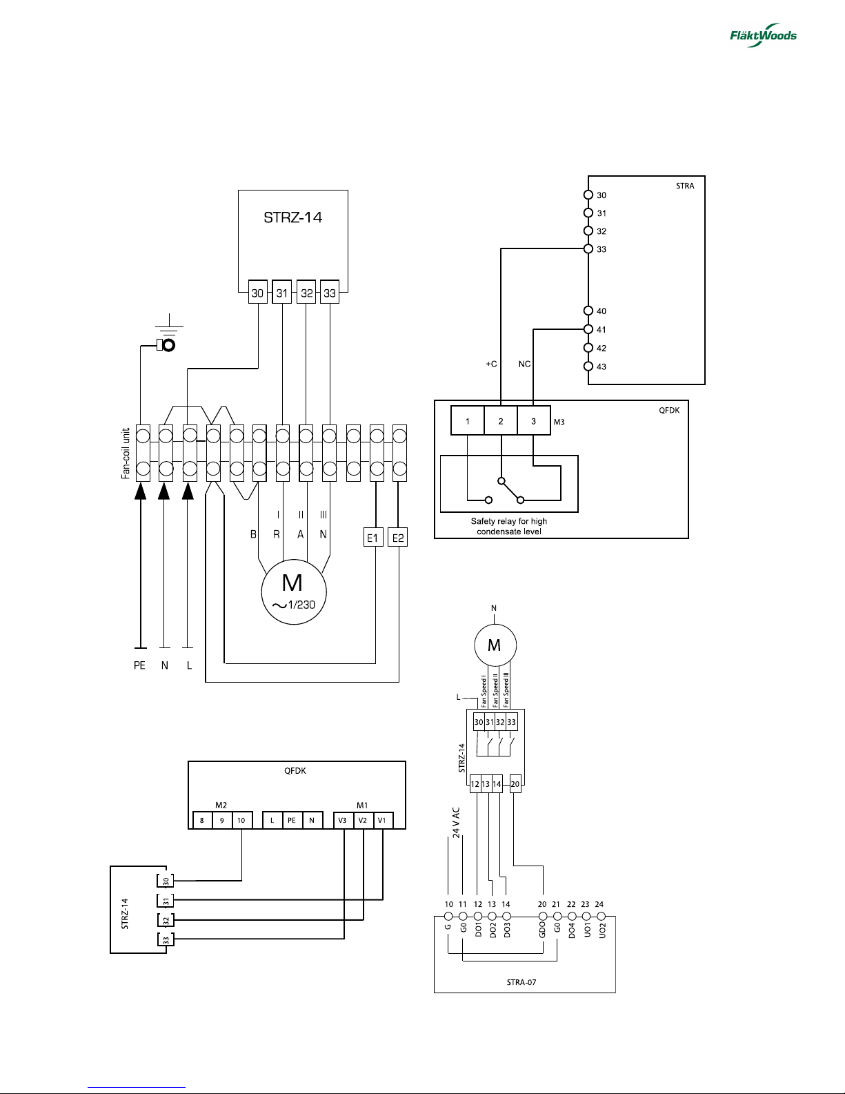
Plug-in of relay-box STRZ-14 to fan coil unit
QFDK, mounted in ceiling
Plug-in of condensation detector
Plug-in of relay-box STRZ-14 to STRA-07
 Loading...