

flakt woods STRA-04 Installation & Maintenance Manual

STRA-04 Room controller. Installation and maintenance manual.
Fläkt Woods
8790 GB 2016.03
1
Specifications are subject of alteration without further notice.
Contents STRA-04 for Optivent
Installation instructions........................................................................2
Controller................................................................................................3
Display handling...................................................................................3
Technical data........................................................................................4
Configuration........................................................................................4
Operating modes..................................................................................6
Control...................................................................................................7
Condensation detector/Window contact/Frost protection.............8
Parameter settings................................................................................9
Function key........................................................................................11
STRA-04 Room controller. Installation and maintenance manual.
Fläkt Woods 2
Specifications are subject of alteration without further notice.
STRA-04 for Optivent
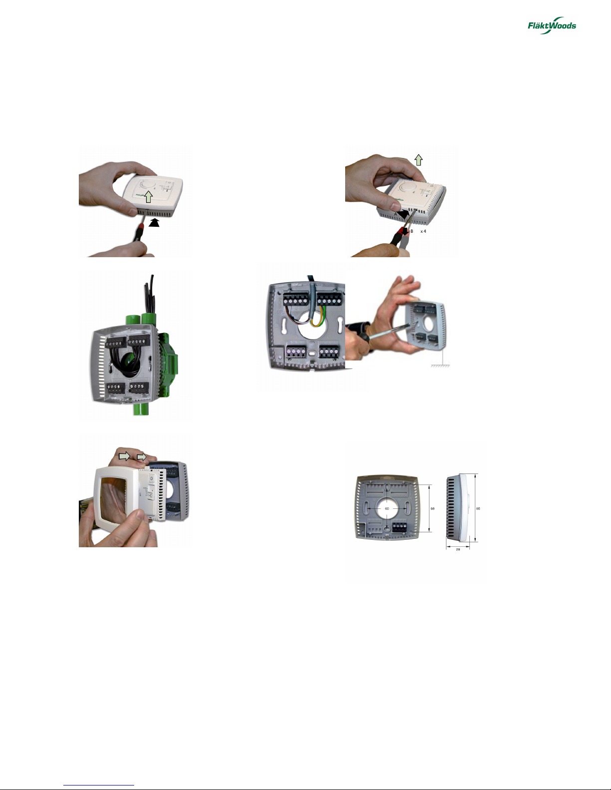
Installation instructions
Follow local safety regulations when installing the product. For information on putting the product into operation, see
the manual "STRA Manual", which can be downloaded from www.flaktwoods.com.
1. 2.
3.
or
4.
5. Dimensions
Dimensions given in mm
8790 GB 2016.03
STRA-04 Room controller. Installation and maintenance manual.
STRA-04 for Optivent
Fläkt Woods 3
Specifications are subject of alteration without further notice.
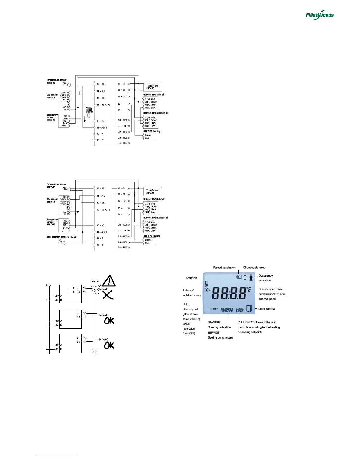
Connection diagram for STRZ-05, STRZ-18, STRZ-09,
STRZ-70, EMSS and window contact STRZ-38
Connection diagram for STRZ-05, STRZ-18, STRZ-09,
STRZ-70, EMSS and condensation sensor STRZ-16
Setpoint adjustment
In Occupied mode, the controller operates from a heating
setpoint (FS = 22°C), or a cooling setpoint FS = 24°C) that
can be changed using the INCREASE and DECREASE
buttons.
When the INCREASE button is pressed, the current
setpoint is raised by 0.5°C per press up to the maximum
limit (FS = +3°C). When the DECREASE button is pressed,
the current setpoint is reduced by 0.5°C per press down to
the minimum limit (FS = -3?).
Switching between heating and cooling setpoints is done
automatically in the controller depending on the heating
and cooling requirement.
Function button
If the Function button is pressed briefly (less than 5
seconds) when the controller STRA-04 is in the Preset
operating mode (Parameter 45, FS = 3 = Occupied), the
controller switches to the Bypass operating mode. If the
button is pressed briefly when the controller is in Bypass
mode, it will switch to Preset mode.
If the Function button is pressed and held for more than
5 seconds, the controller switches to Unoccupied mode,
regardless of the current operating mode. If the button is
pressed briefly in Unoccupied mode, the controller will
return to Bypass (for 60 minutes – this is a preset time that
can be changed via setting of parameter 12).
Display handling
The display on the controller STRA-04 has the following
indications:
8790 GB 2016.03

STRA-04 Room controller. Installation and maintenance manual.
STRA-04 for Optivent
Fläkt Woods 4
Specifications are subject of alteration without further notice.
Different parameter values can easily be set in a
parameter menu shown on the display, using the buttons
on the controller. The parameter value is changed using
the INCREASE and DECREASE buttons, and the change
is confirmed with the Function button.
Technical data
Supply voltage 18...30 V AC, 50...60 Hz
Internal consumption 2.5 VA
Ambient temperature 0...50°C
Storage temperature -20..+70?
Ambient humidity Max 90% RH
Protection class IP20
Communication RS485 (EXOline or Modbus) with
automatic detection/change-over
Modbus - Bacnet 8-bit, 1 or 2 stop bits. Odd, even (FS) or
no parity.
Communication speed 9600 bps (not changeable)
Built-in temperature sensor NTC type, measuring range, 0...50°C,
measurement accuracy +/-0.5°C at
15...30°C
Material casing Polycarbonate, PC
Weight 110 g
The product meets requirements for
prevailing European EMC standards
CENELEC EN 61000-6-1 and EN
61000-6-3 and prevailing European
LVD standard IEC 60 730-1. The
product is CE marked.
Inputs
External room sensor PT1000 sensor, 0…50°C. A suitable
sensor is Fläkt Woods STRZ-05.
Occupancy detector Closing potential-free contact. A
suitable occupancy detector is Fläkt
Woods STRZ-09.
CO 2 sensor STRZ-18-1-1 CO 2 sensor (0-10V).
Outputs
Forced ventilation 24 V AC actuator, max. 0.5 A
Valve actuator, thermal actuator
or Optivent 2 outputs
Valve actuator 0…10 V DC, max. 5 mA
Thermal actuator 24 V AC, max. 2.0 A
Control Heating or cooling
Exercise FS = 23 hour intervals
Terminal block Lift-type for max. cable cr oss-section
2.1 mm
2
Connection
To keep the unit as compact as possible, the
communication input on the STRA-04 is not galvanically
separated from the supply voltage. This means that it is
vital to be able to distinguish clearly between G and G0,
as well as the communication input's A and B.
All STRA regulators that share a transformer and
communication loop must use the same transformer pole
for G (terminal 10) and G0 (terminal 11), respectively. On
the communication loop, the A terminal (terminal 42)
may only be connected to another A terminal, and the B
terminal (terminal 43) to another B terminal. Otherwise
there is a high risk of short circuiting, which would ruin
the components.
Configuration
Use the parameter menu in the display to configure the
electronic unit. See the Parameter Settings section.
8790 GB 2016.03
 Loading...