

flakt woods PM Installation And Maintenance Instructions Manual
AIR COMFORT
AIR TREATMENT
9191 GB 2015.09.29
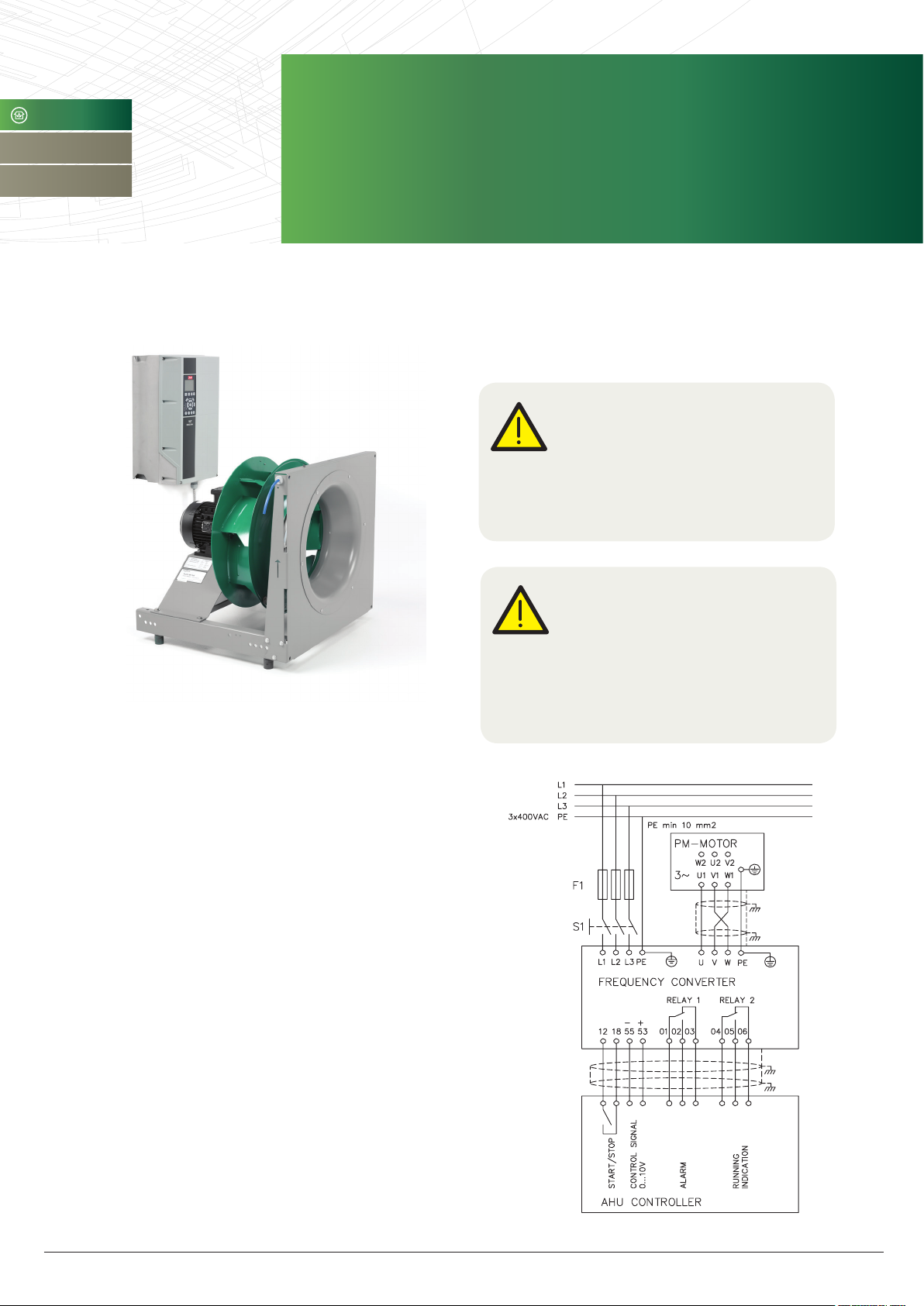
FLÄKT WOODS PM-MOTOR
WITH SUPPLIED FC 102 FREQUENCY CONVERTER
» INSTALLATION AND MAINTENANCE INSTRUCTIONS
INSTALLATION
Warning!
The motor is designed exclusively for
operation with the supplied speed control
(frequency converter).
Direct on-line connection to the mains is not
possible for PM-motors.
GENERAL
• Admissible environmental temperature: from -15 °C up to
+40 °C, with altitudes 1000 m above sea level
• Mounting: IM B3, B5
• Drive operating voltage: 400 VAC
• Insulation class: "F"; temperature rise to class B
(TEFC execution)
• IP55 degree of protection for the whole range
• Reduced dimensions
• Rare earth permanent magnets
Speed controller and motor shall be installed by a qualified
electrician with adequate knowledge how to install speedcontrolled drive systems (frequency inverters) and EMC safety.
All cabling must comply with national and local regulations on
cable cross-sections and ambient temperature.
Warning!
Risk of electric shock:
Motor terminals may still be live if the impeller
is rotating, even when the main incoming
supplied has been isolated.
Ensure the impeller is kept stationary before
opening and whilst the terminal box is open.
Fläkt Woods 9191 GB 2015.09.24 Specifications are subject to alteration without notice

Installation and maintenance instructions
Fläkt Woods PM-Motor
With suPPlied FC 102 FrequenCy Converter
2
SUPPLY CABLE
Mount mains supply to terminals L1, L2 and L3 and ground
wires to earth terminal and tighten.
Short circuit protection:
The speed controller must be protected against shortcircuit to
avoid electrical or fire hazard. The fuses mentioned below are
recommended to use to protect service personnel and equipment in case of an internal failure in the speed controller. Speed
controller provides full short circuit protection in case of a short
circuit on the motor output.
Over current protection:
Provide overload protection to avoid fire hazard due to overheating of the cables in the installation. The speed controller
is equipped with an internal over-current protection that can
be used for upstream overload protection (UL-applications
excluded). See par. 4-18
Current Limit. Moreover, fuses or circuit breakers can be used
to provide the over-current protection in the installation. Overcurrent protection must always be carried out according to
national regulations.
Leakage Current (>3,5mA)
EN/IEC61800-5-1 (Power Drive System Product Standard)
requires special care if the leakage current exceeds 3,5 mA.
Earth grounding must be reinforced in one of the following
ways:
• Earth ground wire of at least 10 mm
2
• Two separate earth ground wires both complying with the
dimensioning rules
Isolation switch
All speed controllers may be used with an isolated input source as well as with ground reference power lines.
RECOMMENDED PRE-FUSES
Power 0,75 1,5 2,2 3 4 5,5 7,5 11 15
3x380-
400V
UL (A) 10 10 15 15 15 25 25 50 50
IEC (A)
type gG
10 10 16 16 16 25 25 50 50
MOTOR CABLE
Motor and speed controller is delivered with 3,5 m long motor
cable. If it should be replaced with longer one or disconnected
at the other end.
Following rules should be meet and considered:
• Motor cable should be shielded type.
• Shield should be grounded 360° at both ends of cable.
• Motor cable should be no longer than 20 meters.
• Motor is connected to star inside the motor.
• Phase wires are connected to terminals U1, V1, W1.
• Terminal connectors are not needed.
CONTROL CABLE
Control cable should be shielded. Keep control cable distance
min 200 mm from mains and motor cable.
CONTROL SIGNALS
Fan is started with potential free switch connected between
terminals 12 and 18. The circuit voltage is 24 VDC. AUTO-mode
should be selected from operation panel.
Speed reference can be given from with 0…10 V signal
connected in terminals 53(+) and 55(-). Alarm signal is available in relay1 (terminals 01, 02 and 03).
Running indication is available in relay 2 (terminals 04,
05 and 06).
Single speed operation:
Set constant speed reference (rpm) in parameter 411.
Only external start signal is needed.
Two speed operation:
Lower speed reference (rpm) is set in parameter 411 and
higher speed reference (rpm) in parameter 319. Lower speed
is activated with start signal (terminals 12-18). Higher speed is
activated by closing terminals 12-29. Speed controller can be
controlled via Modbus RTU. RS-485 cable is connected to the
terminals 68 (P), 69 (N) and 61 (COM). If speed controller is last
unit in line, it should be terminated by setting switch S801 in
ON position. Modbus operation is described in speed controller
operation instructions.
START UP AND FUNCTIONAL TESTING
After power up test check motor rotation:
Set speed controller to Hand on mode from operation panel.
Motor will start to the minimum or speed set in operation panel.
To change the direction of rotation:
• Remove power to the speed controller and wait for power to
discharge.
• Reverse the connection of any two of the three motor cables
on the motor or frequency converter side of the connection.
When direction of rotation is right set speed controller to Auto
on mode. Then speed controller will follow control signals.
PARAMETERS
Speed controller parameters are set at the factory providing
for optimal performance of fan and motor. This includes motor
parameters, ramp times, starting and stopping methods and
speed limitations. Changing of these parameters may result
in unstable operation or motor won’t start. Original parameter
values can be downloaded from operation panel in case of
losing them.
Fläkt Woods 9191 GB 2015.09.24 Specifications are subject to alteration without notice
 Loading...