

FlaktWoods ECONOVENT – PUM Technical Handbook
ECONOVENT®– PUM
Rotary heat exchanger
Technical Handbook

Fläkt Woods 3099 US 03.02 2 Specifications are subject to alteration without notice
PUMA (A–F) Rotary heat exchanger TECHNICAL HANDBOOK
CONTENTS
Design . . . . . . . . . . . . . . . . . . . . . . . . . . . . . . . . . . . . . . . . . . . . . . . . 3,4
Design – Description – Accessories
. . . . . . . . . . . . . . . . . . .5,6
The process in the psychrometric chart
. . . . . . . . . . . . .7,8,9
Rotor selection
. . . . . . . . . . . . . . . . . . . . . . . . . . . . . . . . . . . . . . . .10
Selection of heat exchanger type and size
. . . . . . . . . . . . .11
Efficiency
. . . . . . . . . . . . . . . . . . . . . . . . . . . . . . . . . . . . . . . . . . . . .12
Design chart
. . . . . . . . . . . . . . . . . . . . . . . . . . . . . . . . . . . . . . . . . .
13
Project design advice
. . . . . . . . . . . . . . . . . . . . . . . .14,15,16,17
Control Systems
. . . . . . . . . . . . . . . . . . . . . . . . . . . . . . . . .17,18,19
Installation
. . . . . . . . . . . . . . . . . . . . . . . . . . . . . . . . . . . . . . . . .20,21
Dimensions and weights
. . . . . . . . . . . . . . . . . . . . . . . . . . .22,23
Ordering key
. . . . . . . . . . . . . . . . . . . . . . . . . . . . . . . . . . . . . . .24,25
Sample specification
. . . . . . . . . . . . . . . . . . . . . . . . . . . . . . . .26,27
Fläkt Woods 3099 US 03.02 3 Specifications are subject to alteration without notice
PUMA (A–F) Rotary heat exchanger TECHNICAL HANDBOOK
Design
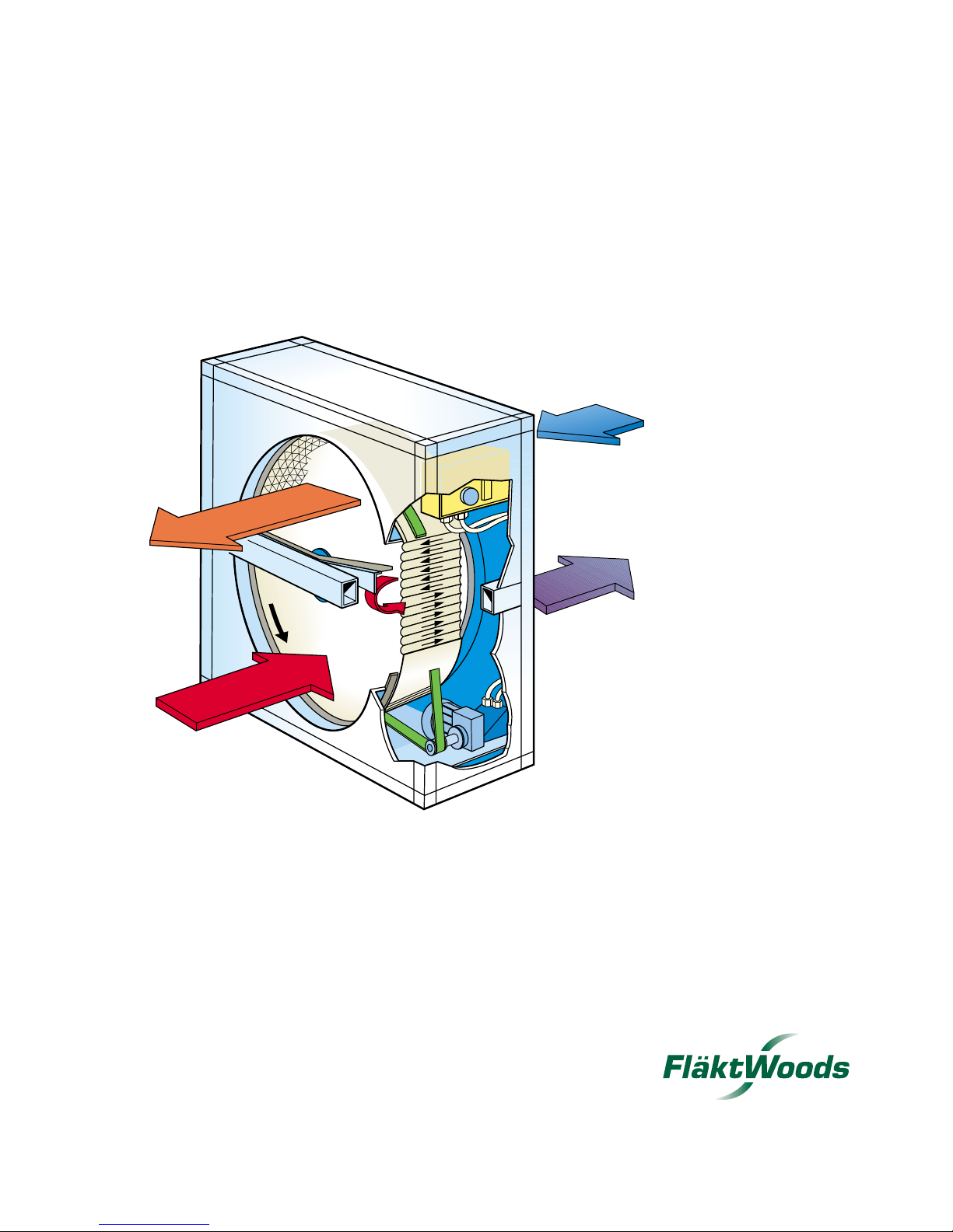
The ECONOVENT unit is a regenerative heat
exchanger comprising a rotor which transfers heat and
moisture from the exhaust air to the supply air as it
rotates.
The supply air flows through one half of the heat
exchanger, and the exhaust air flows in counterflow
through the other half. Supply air and exhaust air thus
flow alternately through small passages in the rotor in
opposite directions.
Most important benefits:
Reduced heat demand which, in turn, reduces the size
and thus also the investment cost for the boiler station
or the connection charge for tariff-linked heat, such as
electric power and heat from the district heating system.
In addition, the sizes and thus the investment costs for
air heaters, pipes and pumps are reduced.
Reduced heat energy demand, which reduces the
operating costs, i.e. the oil consumption or the con-
umption charge for electrical energy or heat from the
district heating system.
Reduced energy consumption for humidification
(hygroscopic rotors) of the air, since moisture is also
recovered.
Reduced cooling power demand (hygroscopic rotors)
which reduces the size and thus also the investment
cost for the refrigeration system (compressor, cooling
tower, etc.), air coolers, pumps and pipes.
Reduced energy consumption for refrigeration
(hygroscopic rotors).
General reduction in environmental pollutants.
ECONOVENT is a complete product range of rotary
heat exchangers for air handling systems in various types
of environments and plants. ECONOVENT is available
with six different materials for the rotor, and the right
material can therefore always be specified to suit most
environments.
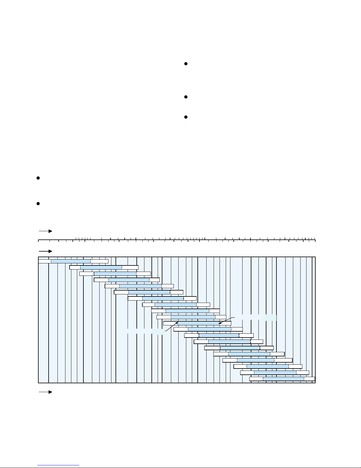
2000 3000 4000 5000 10 000 20 000 30 000 50 000
Air flow, m
3
/h
Air flow, m
3
/s
100 000 150 000
0.4 0.5 1 2 3 4 5 10 20 30 40 500.30.2
Air flow, CFM
500 1000 2000 3000 4000 5000 10 000 20 000 30 000 50 000 100 000
060
080
095
110
135
150
170
190
200
215
240
265
290
320
350
380
420
460
500
120
Size
Air velocity 400 FTM
Air velocity 900 FTM
FPM
FPM
Fläkt Woods 3099 US 03.02 4 Specifications are subject to alteration without notice
PUMA (A–F) Rotary heat exchanger TECHNICAL HANDBOOK
Design
General
The heat exchanger consists of a casing, a rotor of hygroscopic or non-hygroscopic type, and a rotor drive unit.
Adjustable seals are fitted between the casing and the
rotor on both sides, in order to minimize the leakage of
air. The heat exchanger can be ordered either with or
without purging sector.
The purging sector is adjustable and prevents the carryover of exhaust air to the supply air.
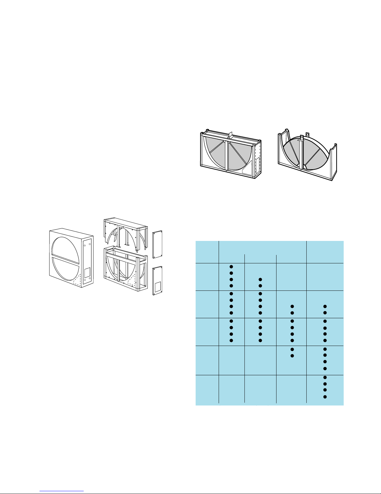
Casing for sizes 060–240
The casing is of single-skin design and is made as one
unit. An inspection panel (2 panels for size 190 and larger sizes) is located on the end wall or front (optional) of
the casing as shown in Fig. 1. The drive motor and speed
controller (for a variable speed unit) are fitted and tested
at the factory. Note that a split casing as shown in Fig. 2
is available for size 150 and larger sizes.
Casing for sizes 265–500
The casing is of single-skin design and is delivered split,
as shown in Fig. 3. Size 265 and 290 units can also be
ordered assembled at the factory. Inspection panels are
located on the front or on the end wall (optional) of the
heat exchanger as shown in Fig. 3. The drive motor is
installed on the inside of the inspection panel. Access
panels are provided on the front of the casing for installation of the rotor sector.
Fig. 1
Fig. 2
Inspection panel
standard
Inspection panel, optional
Inspection panel
standard
Inspection panel, optional
Fig. 3.
Delivery
The ECONOVENT PUM(A-F) Heat exchanger is delivered as shown in Table 1.
● Standard. 1) A composite rotor (PUMF) is always sectorized.
One factory-assembled unit Split casing
Split casing ( 2 units)
Size One-piece Sectorized Sectorized Sectorized
bbb rotor
1)
rotor rotor rotor
060
080
095 ●
110
120 ●
135
150
170
190
200
215
240 ●
265
290
320
350
380
420
460
500
Delivery form in split version.

Fläkt Woods 3099 US 03.02 5 Specifications are subject to alteration without notice
PUMA (A–F) Rotary heat exchanger TECHNICAL HANDBOOK
Design - Description - Accessories
Drive system
The drive system consists of an electric motor (constant
speed or variable speed) with reduction gear, driving the
rotor by means of a jointed V-belt. The V-belt is kept
automatically tensioned by the spring-mounted motor
bracket.
Temperature limit
The heat exchanger is suitable for use at temperatures up
to +165°F.
The temperature in the motor compartment must not
exceed +100°F. If the supply or exhaust air temperature
exceeds +100°F, see further under Temperature limit on
page 19.
Materials and finish
Frame Sizes 060–240: galvanized sheet metal
Sizes 265–500: rotor support steel beams
primed with anti-corrosion
paint.
Cover panels, inspection panels and purging sector: galvanized sheet metal.
Hub (one-piece rotor): aluminum
Hub (sectorized rotor): steel, primed with anti-
corrosion paint.
Rotor material
ALUMINUM ROTORS (A, C and E rotors) are nonhygroscopic, i.e. they recover only sensible heat, as long
as condensation does not occur.
ALUMINUM ROTORS (B and D rotors) are hygroscopic and recover both sensible heat and latent heat
(on changing moisture content).
COMPOSITE ROTORS (F) rotors are hygroscopic, i.e.
they recover both sensible heat and latent heat. The composite material is incombustible and contains no metals,
which means that the material cannot corrode.
The material is treated with silica gel-based substances.
GENERAL SURVEY OF ROTORS
ECONOVENT
Material Property
Max temperature -
rotor designation
range, °F
A Aluminum Non-hygroscopic 165
B Aluminum Hygroscopic 165
C Edge-reinforced aluminum Non-hygroscopic 165
D Edge-reinforced aluminum Hygroscopic 165
E Epoxy-coated aluminum Non-hygroscopic 165
F
Composite Hygroscopic 165
1)
Heating and cooling energy recovery in air handling systems
- without moisture transfer.
Heating and cooling energy recovery in air handling systems
- with moisture transfer.
Heating and cooling energy recovery in air handling systems
- without moisture transfer in a corrosive environment.
Heating and cooling energy recovery in air handling systems
- with moisture transfer in a corrosive environment.
Heating and cooling energy recovery in air handling systems
- without moisture transfer in corrosive environment.
Heating and cooling energy recovery in air handling systems
- with moisture transfer in corrosive, city, marine and
coastal environments.
Application
1) Available for a max. temp. of 275°F. Get in touch with Munters International Inc.

Fläkt Woods 3099 US 03.02 6 Specifications are subject to alteration without notice
PUMA (A–F) Rotary heat exchanger TECHNICAL HANDBOOK
Design - Description - Accessories
Accessories
PUMZ-17 Duct connection frames
Slip joint connection, made of galvanized sheet metal and
fitted to the heat exchanger at the factory.
PUMZ-20 Speed detector
Used for continuous monitoring of the rotor speed, with
automatic alarm if the rotor should stop when heat recovery is needed.
An alarm relay and sensor unit are needed for a constantspeed exchanger. Only the sensor unit is needed for a
variable-speed exchanger.
PUMZ-21 Differential thermostat
In cooling energy recovery, used for switching the heat
exchanger to maximum speed when the outdoor temperature is higher than the exhaust air temperature. Two sensors are included for fitting in the outdoor air and
exhaust air ducts upstream of the heat exchanger.
PUMZ-27 Cleaning equipment
For automatic purging of the air passages in the rotor.
With compressed air nozzle which is moved by means of
a pneumatically actuated cylinder in a radial direction
along the face of the rotor. Nozzle, cylinder and control
unit are included.
For assistance in selecting the variant and locating the
equipment, please get in touch with Munters
International Inc. representative.
PUMZ-28 Condensate tray
For collecting and disposal of the condensate from the
rotor.
Fläkt Woods 3099 US 03.02 7 Specifications are subject to alteration without notice
PUMA (A–F) Rotary heat exchanger TECHNICAL HANDBOOK
The process in the psychrometric chart
35
70
105
140
175
-20 -10 0 10 20 30 40 50 60 70 80 90
Dry Bulb Temperature°F
Humidity Ratio
grains/lb
100 110 120
0
5
10
15
20
25
30
35
40
45
50
20%
40%
60%
12.0
12.5
14.5
14.0
13.513.0
80%
Chart 1
Non-hygroscopic rotors - type A, C and E
In type A, C and E NON-HYGROSCOPIC rotors, only
sensible heat exchange takes place as long as there is no
condensation in the rotor. As soon as condensation
occurs, the condensate will evaporate in the supply air.
The graphic presentation of the process in the psychrometric chart when condensation takes place varies with
the operating conditions and can therefore not be specified generally.
Outdoor air summer
Exhaust air summer
Exhaust air winter
Outdoor air winter
Fläkt Woods 3099 US 03.02 8 Specifications are subject to alteration without notice
PUMA (A–F) Rotary heat exchanger TECHNICAL HANDBOOK
The Process in the psychrometric chart
35
70
105
140
175
-20 -10 0 10 20 30 40 50 60 70 80 90
Dry Bulb Temperature°F
Humidity Ratio
grains/lb
100 110 120
0
5
10
15
20
25
30
35
40
45
50
20%
40%
60%
12.0
12.5
14.5
14.0
13.513.0
80%
Chart 2
Hygroscopic rotors - type B, D and F
In type B, D and F HYGROSCOPIC ROTORS, the
moisture and temperature efficiencies at full speed are
equal. As a result, the process in the psychrometric chart
runs along the interconnecting line between the inlet
conditions for the supply and exhaust air
Outdoor air summer
Exhaust air summer
Exhaust air winter
Outdoor air winter

Fläkt Woods 3099 US 03.02 9 Specifications are subject to alteration without notice
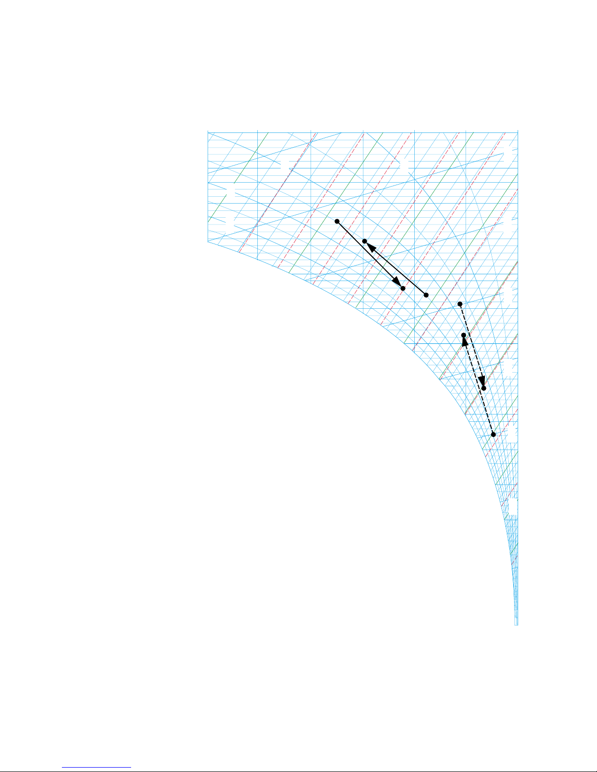
PUMA (A–F) Rotary heat exchanger TECHNICAL HANDBOOK
The Process in the psychrometric chart
Summer operation
Charts 1 and 2 show summer conditions in which the outdoor air is warmer and more humid than the exhaust air.
The hygroscopic rotor (Chart 2) lowers both the moisture
content and the temperature to the vicinity of the exhaust
air conditions, and gives an enthalpy efficiency of 75%. The
nonhygroscopic exchanger (Chart 1) lowers the temperature
by the same amount, but does not change the moisture content. In this case the supply air enthalpy efficiency will be
only about 25%. The example illustrates the significance of
the high moisture efficiency of the hygroscopic rotor, above
all in humid, warm climates.
Winter operation
Charts 1 and 2 show a winter case with moderately low
outdoor temperatures. No condensation takes place in the
nonhygroscopic rotor, (Chart 1) which therefore does not
contribute to the moisture content of the supply air. On
the other hand, the hygroscopic rotor (Chart 2) raises the
moisture content of the supply air by almost 11 Gr/lb of
air, which usually offers welcome humidification of the
supply air. The nonhygroscopic rotor can operate without
risk of freezing even when condensation takes place at
temperatures below 32°F.
Frosting - Defrosting
Rotor temperatures below 32°F need not necessarily cause
frosting in the rotor. Moisture transfer then takes place by
the moisture, which has been deposited as frost on the
rotor surface, being evaporated on the supply air side. For
frosting to occur, there must also be excess water in the
rotor. This will take place if the supply air is not capable
of absorbing the moisture that has condensed out of the
exhaust air.
The frosting process, which causes an increase in pressure
drop across the rotor, normally takes many hours. The
frosting problem is therefore often relieved by the outdoor temperature varying over a 24 hour period, or
because the heat exchanger is in operation during only
part of the 24-hour period.
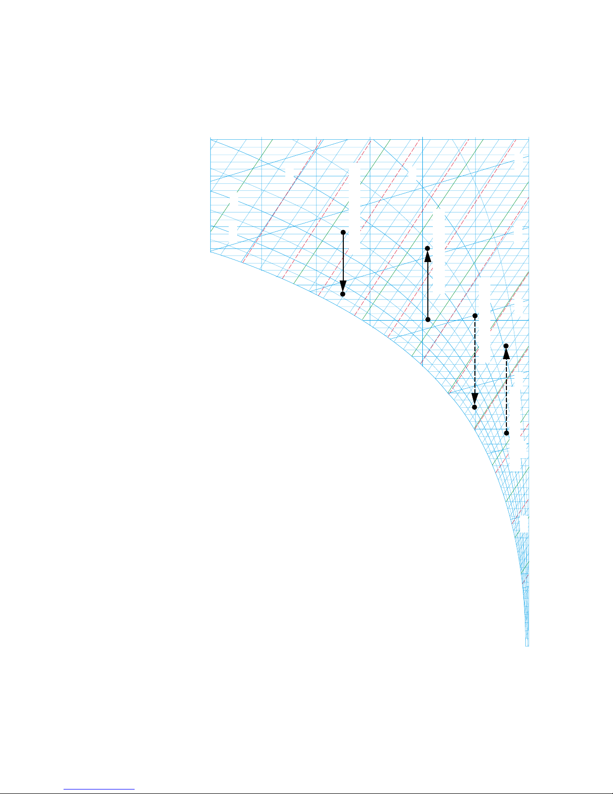
Frosting limit
Frosting will occur if excess water should occur, at the
same time as the supply air inlet temperature is below
14ºF. This temperature applies with relatively good accuracy at different airflow rates, full speed and typical
exhaust air temperatures occurring in comfort ventilation
systems.
Excess water will occur in the hygroscopic rotor as soon
as the interconnecting line between the inlet conditions
for the two air streams intersects the saturation line in the
psychometric chart (see Chart 3).
In the case of a nonhygroscopic rotor, excess water will
form when the interconnecting line between the supply
air condition and the exhaust air dewpoint plus approximately 7ºF, as shown in Chart 4, intersects the saturation
line in the psychometric chart.
Frosting time
As an example, it will take about 8 hours for the pressure
drop to increase by 50% if the saturation curve is intersected as shown in Chart 3, and about 4 hours if the saturation curve is intersected as shown in Chart 4.
Note that the frosting time will be as above if the temperature and moisture conditions are constant throughout
the frosting time. But since the temperature often varies,
the frosting time may be appreciably longer. As a result of
factors such as operating time and supply air temperature
variations, experience shows that a minor intersection of
the saturation curve is permissible without significant
frosting occurring, even if the design outdoor temperature is below 14°F.
Defrosting - avoidance of frosting
Frosting can be totally avoided by preheating the outdoor
air to a temperature so that the line connecting indoor
and outdoor conditions in the psychometric chart falls
below the saturation line. Heating to 14ºF is normally
adequate. The rotor can be defrosted, normally within
5–10 minutes, in several ways.
– By reducing the rotor speed to around 0.5 r/min (see
example 5 page 22).
– By preheating the incoming outdoor air to around
23°F.
– By bypassing a sufficient amount of supply air across
the rotor so that the outlet temperature on the
exhaust air side will be at least around 41°F. As an
example, the supply air flow rate would have to be
reduced to around half for defrosting to take place at
the normal exhaust air temperature, at a 75%
temperature efficiency and an outdoor temperature
of about –4°F.
All three methods can be used for a variable speed rotor
drive, while the last two can be used with constant speed
drive.around half for defrosting to take place at the normal exhaust air temperature, around 75% temperature
efficiency and an outdoor temperature of about –4°F.
All three methods can be used for a variable-speed rotor,
while the last two can be used at constant speed.
 Loading...