

Page 1
HEAT RECOVERY UNIT
MINIMASTER RDKS
INSTALLATION, OPERATION, MAINTENANCE AND SPARE PARTS
Page 2

2
CONTENTS
OPERATION AND MAINTENANCE (FOR USER)
Functions, system design, electrical data, energy class ............................................... 3
ISYteq Basic control panel
Operation .................................................................................................................................... 4
Overview of symbols and functions ................................................................................ 5
ISYteq Touch 3.5 control panel .....................................................................................................
General information ................................................................................................................6
Cleaning of the display .........................................................................................................6
General buttons and symbols ............................................................................................6
Home screen ............................................................................................................................ 7
Operation ....................................................................................................................................8
Maintenance and cleaning of heat exchanger and fans ..............................................10
Filter alarm and filter replacement .........................................................................................11
Overheating protection, impeller alarm, temperature alarm, other alarms .......... 12
INSTALLATION (FOR INSTALLER AND SERVICE PERSONNEL)
Dimensions, installation measurements 13
Wiring and connection diagram.............................................................................................. 14
Duct connection, duct insulation .............................................................................................15
Installation options and duct definitions .............................................................................. 16
Installation of unit with accessories .......................................................................................17
Heat recovery unit RDKS - Technical manual
ADJUSTMENT, COMMISSIONING (FOR INSTALLER AND SERVICE PERSONNEL)
Settings, date/time, language ................................................................................................. 22
Login, settings ................................................................................................................................ 23
Adjustment .......................................................................................................................................24
Control panel operation, commissioning ............................................................................ 25
Parameter list ................................................................................................................................. 28
MISCELLANEOUS
Spare parts ..................................................................................................................................... 33
EC Declaration of Conformity ....................................................................................................34
Disposal of products and packaging materials ............................................................... 35
Declaration of Conformity .......................................................................................................... 36
WARNING! THE APPLIANCE MAY BE USED BY CHILDREN OVER THE AGE OF 8, PERSONS (INCLUDING CHILDREN) WITH PHYSICAL,
SENSORY OR MENTAL DISABILITIES OR LACK OF KNOWLEDGE OR EXPERIENCE, PROVIDED THEY HAVE RECEIVED INSTRUCTION
OR INFORMATION ON SAFE USE OF THE APPLIANCE AND UNDERSTAND THE POTENTIAL RISKS. CHILDREN MAY NOT PLAY WITH
THE APPLIANCE. CHILDREN MAY NOT CLEAN OR PERFORM MAINTENANCE ON THE APPLIANCE WITHOUT SUPERVISION.
IN THESE INSTRUCTIONS MUST BE CARRIED OUT BY AN INSTALLER OR SERVICE PERSONNEL.
FläktGroup DC_9295GB_20190326_R5
NOTE! INSTALLATION, ADJUSTMENT AND COMMISSIONING AS DESCRIBED
We reserve the right to make changes without prior notice
Page 3
Heat recovery unit RDKS - Technical manual
6, 10541
121311
7
OPERATION AND MAINTENANCE – FUNCTIONS, SYSTEM DESIGN, ELECTRICAL DATA, ENERGY CLASS
3
FANS
The fans are powered by energy-efficient EC motors. They are easy to
remove for service and maintenance. The speed of the fans can be ad
-
justed independently of each other.
HEAT RECOVERY AND SUPPLEMENTARY HEATING
In climates where the temperature seldom drops below -10 °C, there is
usually no need for supplementary heating. This is because the rotary
heat exchanger recovers enough thermal energy from the extract air (≤
temp
).
85% h
When the outdoor temperature is below -10 °C and the desired supply
air temperature cannot be achieved, a postheater is required, which is
controlled to maintain the set supply air temperature. In very cold are
as, the unit can also be supplemented with a heater that preheats the
outdoor air. This heater starts preheating the air when the outdoor
temperature falls below -12 °C.
The electric heaters have an integrated overheating protection function.
NOTE! THE ELECTRIC POSTHEATER IS ONLY ACTIVATED IF THE
IMPELLER IS IN OPERATION.
FILTER
As standard the unit is fitted with a class (M5) ISO Coarse 85% bag filter. For filter replacement, see page 11.
ETHERNET CONNECTION (OPTIONAL)
This function can be used to connect the unit to an existing network.
In that case, the unit is equipped with an integrated web server, which
makes it possible to read and change certain parameters via a web
browser. The connection can also be used for connection to a superior
system via Modbus TCP/IP.
To optimize the performance of communication, please follow the rec
ommendations below.
- Minimize the number of general broadcasts.
- Only send dedicated traffic to the controller.
- Do not attempt to access the web server when using Modbus TCP-IP.
- Maximum of one Modbus message per second is recommended.
Avoid data bursts.
- Only write to Modbus registers when values have been changed.
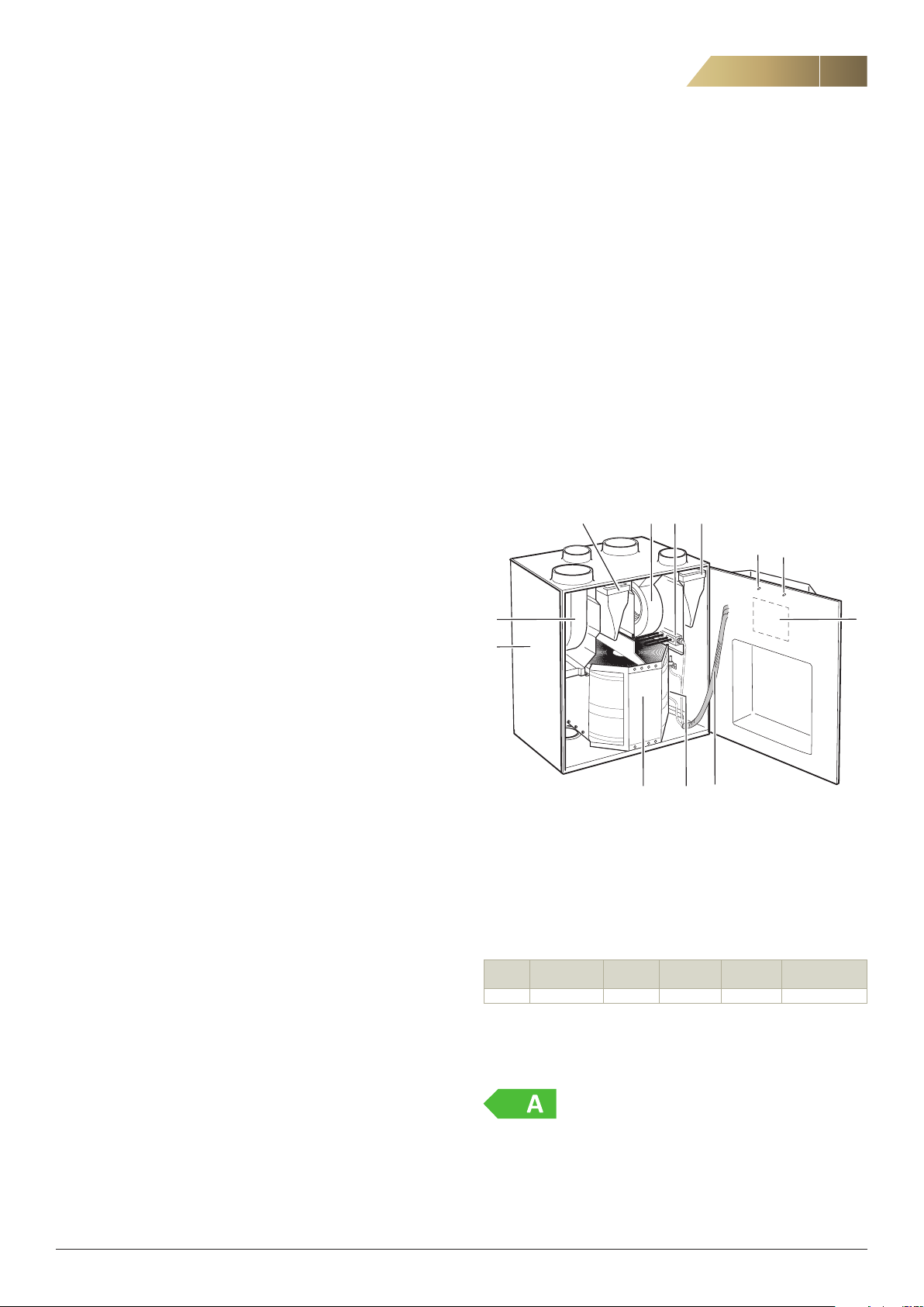
THE UNIT’S MAIN COMPONENTS
3
2
-
8
DEFROSTING
During cold periods, when frost may form in the impeller, the integrated control unit automatically activates a defrosting function. The unit
defrosts for 15 minutes every 6 hours if the outdoor temperature is
below -10 °C. The supply air fan stops and the impeller moves forward
in sections.
COOLING RECOVERY
In the summer, if the extract air is cooler than the outdoor air, the rotary heat exchanger starts to recover cooling from the cooler extract air.
This primarily applies if there is some type of cooling appliance in the
house.
ALARMS
The ISYteq Basic control panel (accessory) has a limited alarm
indicator function. The panel indicates, for instance, when there is a
temperature alarm or when the filter needs replacing.
If the ISYteq Touch 3.5 control panel (accessory) is used, the alarm will
be presented in plain text (see separate instructions).
MOISTURE CONTROL (OPTIONAL)
This function automatically limits the rotary heat exchanger’s moisture
recovery at high indoor humidity levels. This function can also be or
dered retrospectively to supplement the unit.
-
9
1. Outdoor air sensor
2. Extract air sensor
3. Supply air sensor
4. Preheater
5. Extract air fan
6. Heat exchanger
7. Supply air filter
8. Control unit
9. Casing
10. Heat exchanger motor
11. Extract air filter
12. Postheater
13. Supply air fan
ELECTRICAL DATA
Voltage: 230V, single phase, 50 Hz
Code Fan motors
Rated output, W
RDKS 2 x 83 500 500 1170 1210
1)
Rated output applies when both the preheating and the postheating devices are
installed.
Preheater
Electr., W
Postheater
Electr., W
Rated output
1)
Electr., W
Rated output
with cooker hood
ENERGY CLASS
CO2 CONTROL (OPTIONAL)
This function regulates towards a preset setpoint. The fan speed is
automatically adjusted to achieve the desired CO2 level.
NOTE! CO
tion can also be ordered retrospectively to supplement the unit.
FläktGroup DC_9295GB_20190326_R5
control requires a ISYteq Touch 3.5 control panel. This func-
2
Compliant with energy class A+ in cold climate conditions (Scandinavia).
If configured for on-demand control, the unit is compliant with energy
class A in average climate conditions (Central Europe). Ecodesign
Directive 1254/2014.
We reserve the right to make changes without prior notice
Page 4
4
12315 30 60
15 30 60
BOOST
TRICKLE/NORMAL
14:35
21
14:35
21
ISYteq BASIC CONTROL PANEL - OPERATION
Heat recovery unit RDKS - Technical manual
The unit has a built-in control unit that controls the operation of the
fans, the rotary heat exchanger and any electric heaters.
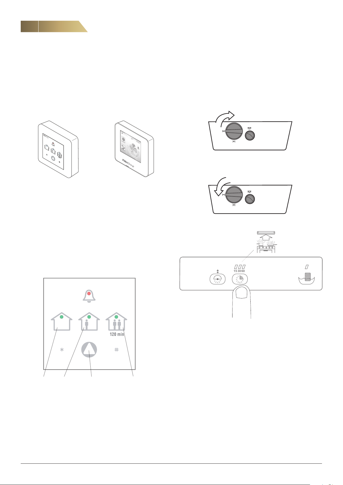
The unit is controlled via an external ISYteq Basic or ISYteq Touch 3.5
control panel (accessory), see page 6. The control unit should be in
-
stalled in a suitable place.
After being adjusted, the unit can also be operated without a control
panel, but only in one operating mode.
ISYteq Touch 3.5ISYteq Basic
Figure 1. Control panels.
The user can select between the following operating
modes:
“AWAY” is used when there is reduced need for ventilation, e.g.
when occupants are on holiday
“HOME” used for normal ventilation flow
“FORCED” is used when there is a greater need for ventilation (au
tomatically reverts to normal after 120 minutes)
Use the arrow button to switch operating modes (see figure 2). A LED
shows the current operating mode.
UNIT WITH COOKER HOOD
When the boost damper in the cooker hood is opened, the fan
speed increases. Forced mode continues while the boost damper
remains open. After that, the fans resume normal speed.
Forced via CPDJ cooker hood.
-
Boost damper
(one press per
time setting)
AWAY
Operating modes ISYteq Basic
FläktGroup DC_9295GB_20190326_R5
HOME
operating mode)
x1 = 15 min
x2 = 30 min
x3 = 60 min
Forced via CPTJ cooker hood.
FORCEDArrow button (for selecting
We reserve the right to make changes without prior notice
Page 5
Heat recovery unit RDKS - Technical manual
ISYteq BASIC CONTROL PANEL - OVERVIEW OF SYMBOLS AND FUNCTIONS
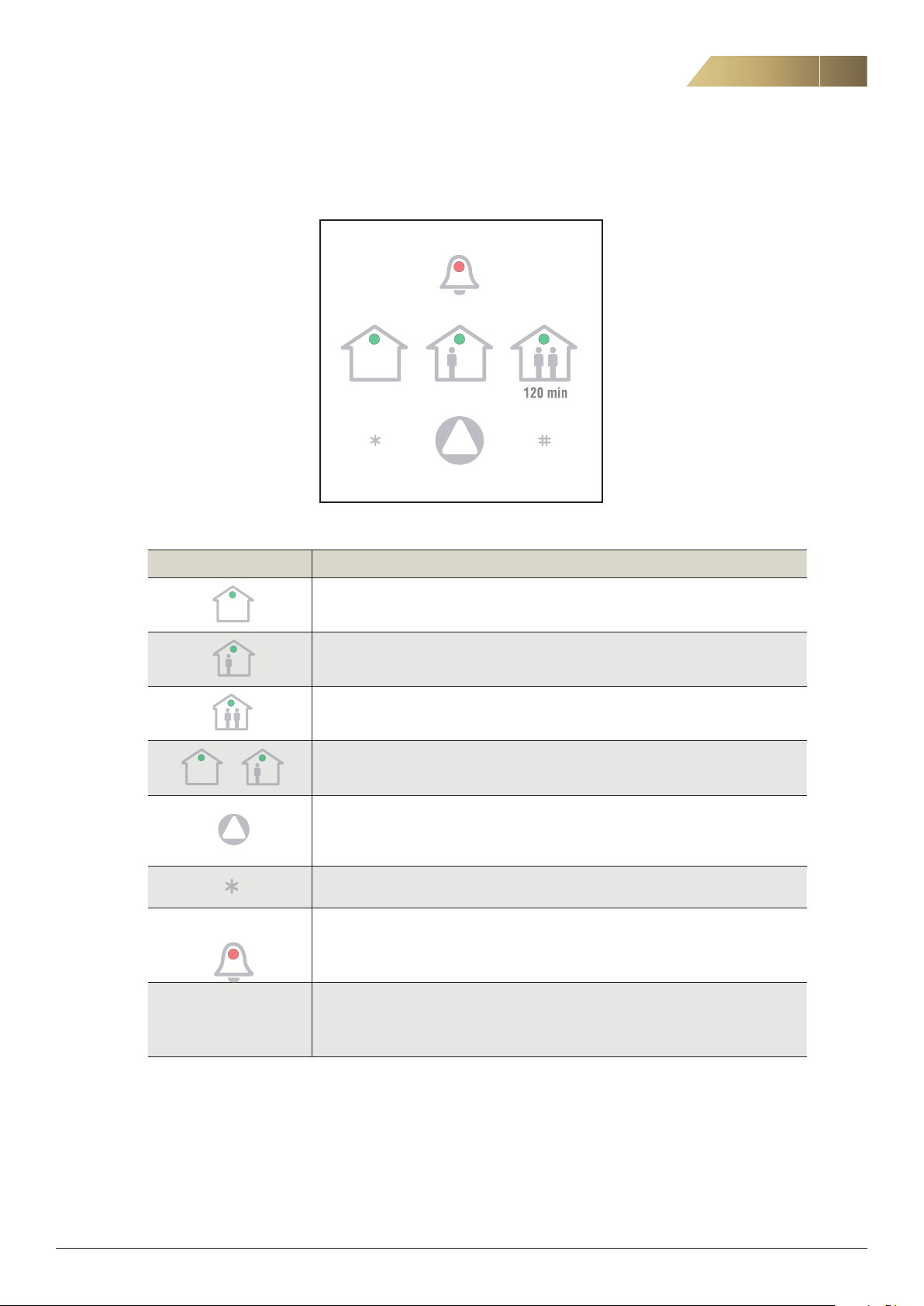
SYMBOLS DURING NORMAL OPERATION
HOMEAWAY FORCED
5
Symbol Description
AWAY mode
HOME mode
FORCED mode for 120 minutes
+
Min. 10 sec. Press * for a minimum of 10 seconds to reset an alarm. Also see pages 11 and 12.
No symbols illuminated
indicates that unit has
stopped.
Defrosting mode. The unit resumes normal operation after 15 minutes
Switch operating modes between: AWAY, HOME and FORCED.
Disabled during defrosting
Continuously flashing alarm symbol indicates filter alarm. See page 11.
Three flashes at intervals indicates rotor alarm. See page 12.
Steady illumination indicates temperature alarm. See page 12.
See Other alarms on page 12.
Figure 5. Symbol description ISYteq Basic.
FläktGroup DC_9295GB_20190326_R5
We reserve the right to make changes without prior notice
Page 6
6
ISYteq TOUCH 3.5 CONTROL PANEL
Heat recovery unit RDKS - Technical manual
GENERAL
The control panel has a touch screen display. Use your finger or the
back of a pen to navigate in the menus.
When the power is switched on, all the menus will be imported into
the system. This will take about 20-30 seconds. After this, the home
screen will be displayed.
CLEANING OF THE DISPLAY
Disconnect the unit from the power supply by disconnecting the power
cord. Carefully wipe the display with a soft, dry, non-abrasive cloth.
If any marks remain, moisten the cloth slightly with a detergent spe
cially designed for LCD or mobile screens and wipe the screen gently
from top to bottom.
Never use other detergents, as they may contain ammonia or other
additives that could damage the display.
-
IMPORTANT:
• Never spray or pour liquids directly onto the display.
• Never clean the control panel when the system is switched on.
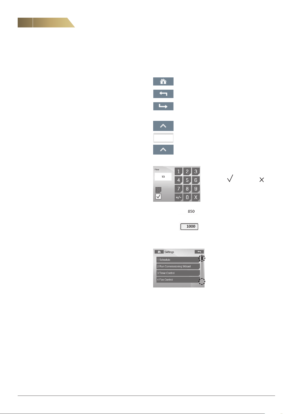
GENERAL BUTTONS AND SYMBOLS
The following buttons and symbols are universal and available on
many menu pages.
Home button, to return to the home screen.
Back button, to cancel and return to the previous page.
Confirm button, to confirm and proceed.
Use the number keys to enter a value.
Confirm with
or cancel with .
14
Changing a value.
Option 1: Press the arrow keys to increase or decrease
the value.
Option 2: Press the displayed number to enter the chosen value (see below).
Read-only values (without a surrounding
window), cannot be changed.
Editable values (surrounded by a win
dow), can be changed.
Some submenus have more than
one page. Click the upper
or lower part of the scroll list to
navigate between pages.
NOTE! The cursor cannot be
moved vertically.
-
FläktGroup DC_9295GB_20190326_R5
We reserve the right to make changes without prior notice
Page 7
Heat recovery unit RDKS - Technical manual
ISYteq TOUCH 3.5 CONTROL PANEL - HOME SCREEN
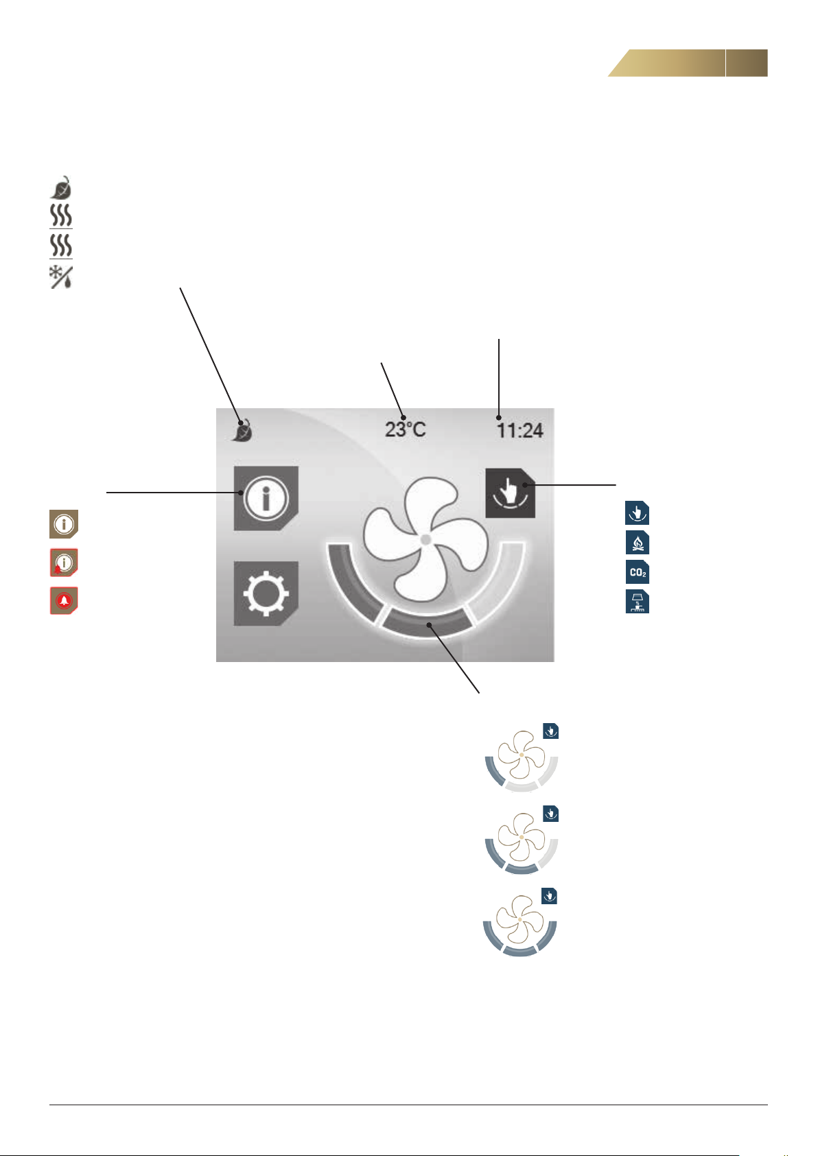
STATUS LINE
Heat recovery active
Postheater active
Preheater active
Defrosting in progress
7
ALARMS
No alarm
Alarm B
Alarm A
CURRENT SETPOINT,
SUPPLY AIR TEMPERATURE
CLOCK
OPERATING STATUS
Manual mode
Heating stove mode
CO2 control
Forced via cooker hood
OPERATING MODES
The user can select between the following operating modes:
“AWAY” used when there is reduced need for ventilation, e.g.
when occupants are on holiday
“HOME” used for normal ventilation flow
“FORCED” used when there is a greater need for ventilation
(automatically reverts to normal after 120 minutes)
FläktGroup DC_9295GB_20190326_R5
Away mode
Home mode
Forced mode
We reserve the right to make changes without prior notice
Page 8
8
ISYteq TOUCH 3.5 CONTROL PANEL - OPERATION
Heat recovery unit RDKS - Technical manual
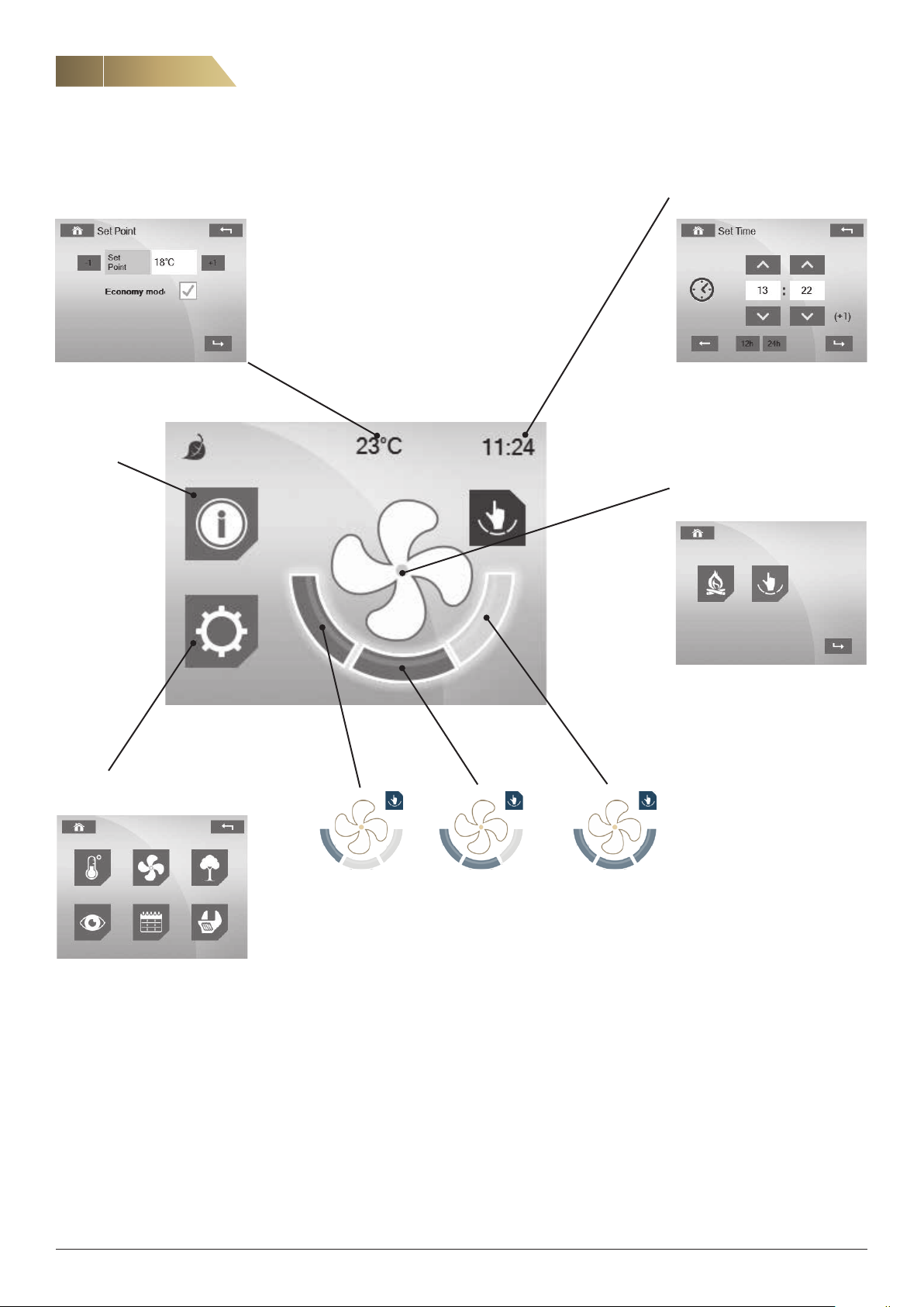
SHORTCUT TO SETTING OF TEMPERATURE SETPOINT
See page 9 for more information on temperatures.
ALARMS
See page 9.
SHORTCUT TO SETTING OF
DATE AND TIME
SELECT OPERATING STATUS
See page 9.
MENU
See page 9.
AWAY MODE HOME MODE FORCED MODE
Press the relevant field to select operating mode.
The operating mode cannot be changed during defrosting,
or during forced operation with a cooker hood.
FläktGroup DC_9295GB_20190326_R5
We reserve the right to make changes without prior notice
Page 9
Heat recovery unit RDKS - Technical manual
ISYteq TOUCH CONTROL 3.5 PANEL - OPERATION
9
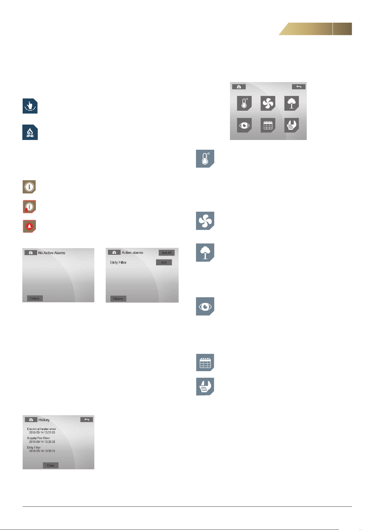
SELECTING OPERATING STATUS
The symbol on the home screen shows the operating status. Press the
centre of the fan symbol to change the status.
Normal mode (manual)
Heating stove mode, makes it easier to light a heating stove
or open fireplace. Temporarily creates overpressure in the
house.
ALARMS
The symbol on the home screen shows the alarm status.
No alarm
Alarm B
Alarm A
Press the icon to enter the alarm screen.
MENU
TEMPERATURES
Here you set the desired supply air temperature (setpoint).
Note: This value is not to be confused with the desired in
door temperature, which is managed by the domestic heating system. The recommended setpoint is 16–19 °C. The
factory setting is 18 °C. Temperatures, output signals etc.
are read-only values.
-
FAN STATUS
Supply and extract air fan speeds can be read from
30 –100 % or as 0 (off).
AIR QUALITY
Air quality (only available if optional moisture control or CO
control is activated). Relative humidity of the supply and
extract air can be read from 0-100% RH.
The setpoint and current CO
be read.
value (up to 2,000 ppm) can
2
2
Example 1 No alarm Example 2. Active alarms
CLEARING ALARMS
To clear an individual alarm, press Acknowledge after the relevant
alarm. To clear all the alarms, press Acknowledge All button (top right).
If the alarm cannot be cleared, it will reappear on the display and the
underlying cause for this must be resolved before the alarm can be
cleared.
A built-in timer is normally set to provide a filter replacement reminder
(alarm) every six months. If a shorter replacement interval is required
(before the alarm is due) the filter alarm can be reset under the Set
tings menu. See page 22, fig. 3.
-
ALARM HISTORY
SYSTEM OVERVIEW
Version control panel -- -- -- -- -- -- -- -- -- -- -- --IP Octet 1
Bootloader control panel --------------------IP Octet 2
Version control card ------------------------IP Octet 3
Bootloader control card -- -- -- -- -- -- -- -- -- -- --IP Octet 4
Unit type
TIME SCHEDULES
(Not applicable to domestic ventilation).
SETTINGS
See pages 22–23.
FläktGroup DC_9295GB_20190326_R5
We reserve the right to make changes without prior notice
Page 10
10
MAINTENANCE AND CLEANING OF HEAT EXCHANGER AND FANS
Heat recovery unit RDKS - Technical manual
GENERAL
The fans, filters and heat exchanger are very important for the operation and economy of the unit. For this reason, it is crucial for them to
be kept clean and in good condition.
We recommend a general check-up every 6 months. For safety rea
sons, general caution should be observed during maintenance of the
unit. Be careful to avoid trapping any cables. If necessary, use protec
tive gloves.
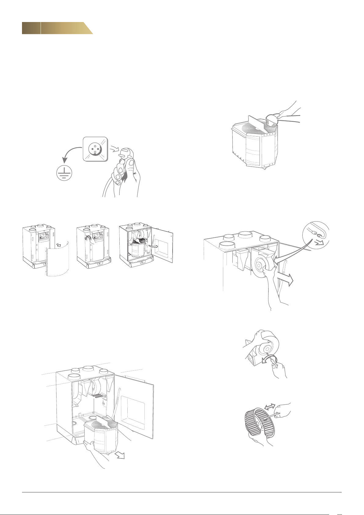
Before cleaning the heat exchanger, fans etc., the unit should always have the power
disconnected.
Mode
LED
Param.
Mode
LED
Param.
-
-
The drive belt and seals may need replacing due to wear and tear.
Check them for damage and replace if necessary. For designations,
see spare parts list on page 33.
Vacuum clean the heat exchanger or blow clean with compressed air.
CLEANING OF FANS
Note that the fans must not be cleaned with water or other fluids; they
may only be vacuum cleaned or brushed.
Remove the unit’s front cover (if there is one). Remove the screws on the door and
open the door. The picture shows a unit with right-hand configuration (RDKS-1).
CLEANING OF THE HEAT EXCHANGER
Check that the surface of the rotor is not coated with dust. Clean with
a vacuum cleaner or by blowing through with compressed air. If vac
uum cleaning is not sufficient, hand-spray with grease dissolving fluid
and then blow clean with compressed air. Use the compressed air to
blow away from the clean side towards the dusty side.
Note! Water, acetone or similar solvents must not be used.
Remove the heat exchanger package from the unit. Disconnect the electrical con
nection to the impeller motor.
-
-
Remove the fan from the unit. Disconnect the electrical connection.
Disconnect the impeller from the fan housing by unscrewing the screws on the side
of the fan housing.
Clean the impeller housing and the fan blades with a brush or a vacuum cleaner.
NOTE! Take care not to damage any impeller housing balancers, and ensure
that no cables are trapped during reassembly.
FläktGroup DC_9295GB_20190326_R5
We reserve the right to make changes without prior notice
Page 11
Heat recovery unit RDKS - Technical manual
B
A
Mode
LED
Param.
FILTER ALARM AND FILTER REPLACEMENT
11
The supply air and exhaust air filters should normally be replaced
every six months. In dirty areas, the filters may need to be replaced
more frequently.
A built-in timer is normally set to provide a filter replacement reminder
every six months.
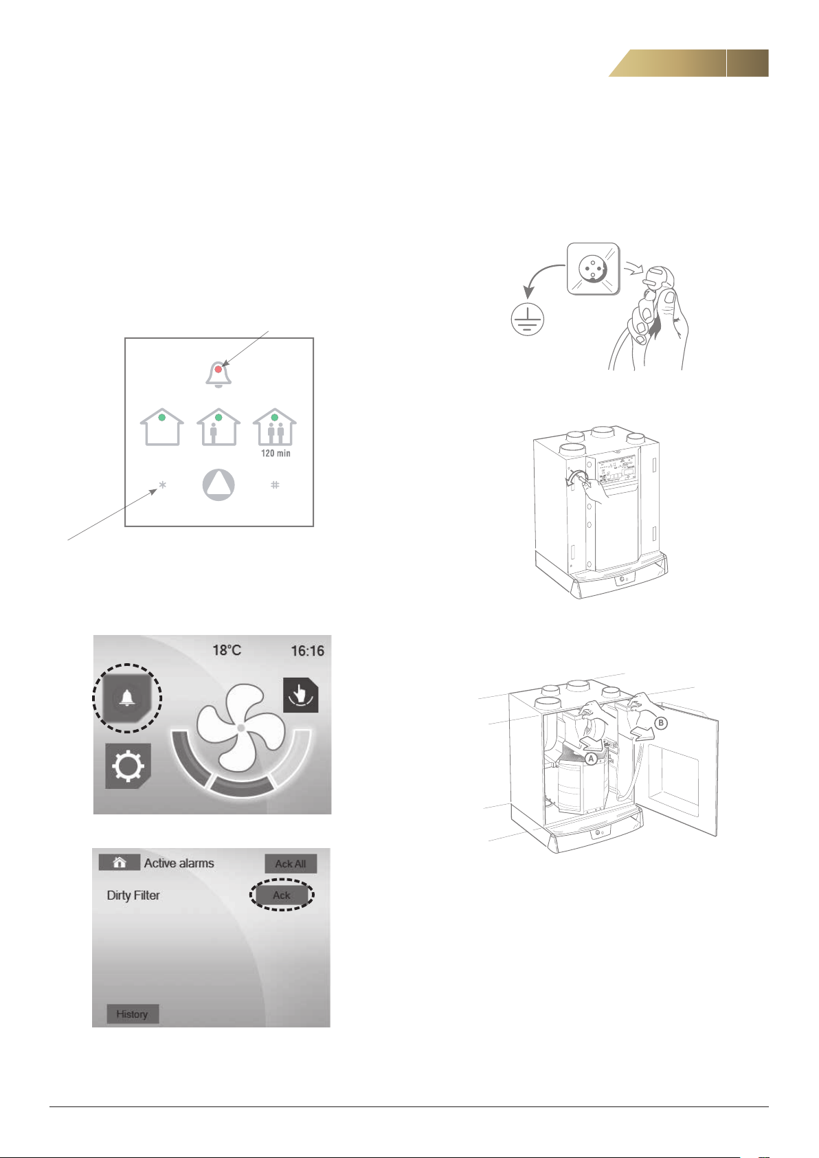
FILTER ALARM ISYteq BASIC
When the filter needs replacing, a continuously flashing alarm light is
shown on the ISYteq Basic control panel.
A continuously flashing alarm
symbol indicates filter alarm.
After replacing the filter, reset the filter timer by pressing the * button on the
control panel for a minimum of 10 seconds.
TO REPLACE THE FILTER, FOLLOW THE STEPS BELOW.
When replacing dirty filters, use of a face mask is recommended (lowest class, FFP2).
1. Disconnect the unit from the power supply by pulling out the plug.
2. Open the door of the unit by unscrewing the two screws on the front
(see below).
FILTER ALARM ISYteq TOUCH 3.5
Press the Information/alarm button if the alarm is indicated.
The reason for the alarm is shown under active alarms.
After replacing the filter, acknowledge the alarm.
3. Pull out the supply air and exhaust air filters. Dispose of used filters
according to local waste regulations.
4. Insert new filters.
The picture shows a bag filter. A flat filter may also be used.
5. Close the door of the unit.
6. Connect the plug.
7. After replacing the filter, reset the filter alarm.
If a filter is replaced before the alarm is due, the filter replacement
timer cannot be reset via the ISYteq Basic control panel (accessory).
If there is no ISYteq Touch 3.5 control panel (accessory) on the unit
when the filter is replaced, the timer must be reset when the alarm is
due, i.e. when the set time is reached. For resetting, see page 22.
FläktGroup DC_9295GB_20190326_R5
We reserve the right to make changes without prior notice
Page 12

12
Heat recovery unit RDKS - Technical manual
OVERHEATING PROTECTION, ROTOR ALARM, TEMPERATURE ALARM, OTHER ALARMS
THERMAL OVERLOAD PROTECTION
The fan motors are equipped with thermal overload protection devices,
which are reset manually by briefly disconnecting the power.
The electric heaters have two thermal overload protection devices, one
automatic and one manual. The automatic overheating protection trips
before the manual one, which means it does not normally need to be
reset.
If the manual overheating protection for the electric heater has tripped
during operation, first the power to the unit should be switched off and
then the overheating protection should be reset by pressing the reset
button.
In order to access the button, the electric heater must be disconnect
ed.
If the manual overheating protection trips again, call qualified service
personnel.
-
ROTOR ALARM
If the rotor motor stops and the Tacho signal disappears, five attempts
will automatically be made to restart the rotor (start/stop). If this does
not solve the problem, the unit will stop and the rotor alarm will be in
dicated.
-
TEMPERATURE ALARM
Generates an alarm and stops operation if the supply air temperature
drops below +5 °C. The alarm is disabled during defrosting or dur
ing forced operation with a cooker hood. A 10-minute delay ensures
that the supply air temperature has time to rise if operation has been
stopped.
-
OTHER ALARMS
The unit has various alarms that are not supported by the simple
ISYteq Basic control panel (accessory).
If any of these alarms are triggered, the unit will stop running and all
the LEDs on the ISYteq Basic will be extinguished. This also happens
in the event of power failure. A LED on the control card indicates that
the power is not switched off.
To reset these alarms, the unit must be restarted by pulling out and
reconnecting the plug.
If the ISYteq Touch 3.5 control panel (accessory) is used, the alarm will
be presented in plain text.
If the alarm recurs, service personnel will be called for assistance.
SENSOR ERROR
If any of the temperature sensors starts malfunctioning, the unit will
stop running. To reset, follow the instructions under Other alarms.
EXTERNAL ALARM
An external alarm can be connected to the unit. If this alarm is triggered, the unit will stop running To reset, follow the instructions under
Other alarms.
FläktGroup DC_9295GB_20190326_R5
We reserve the right to make changes without prior notice
Page 13
Heat recovery unit RDKS - Technical manual
INSTALLATION - DIMENSIONS, INSTALLATION MEASUREMENTS
13
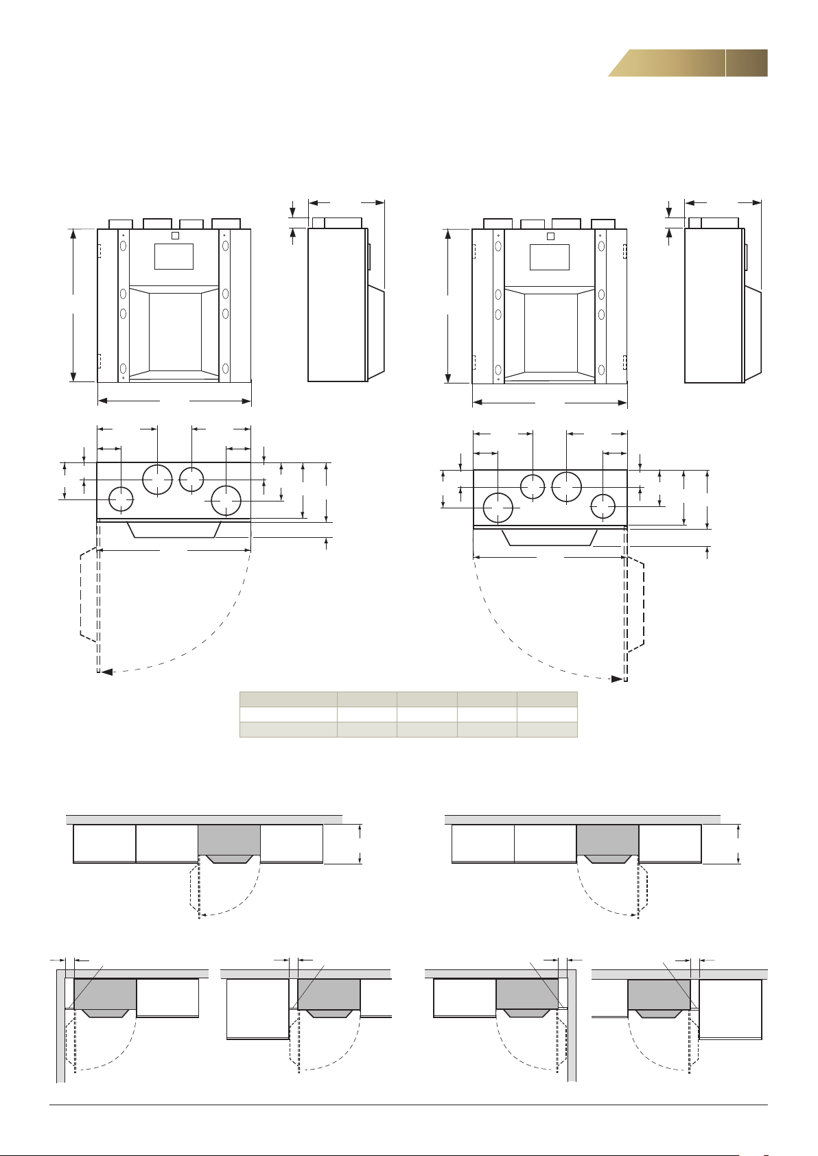
RDKS-2 LEFT
Outdoor air and supply air to the left. Left-hinged door.
32
600
595
188
203 240
70
83
U
T
595
115
F
78
183
265
A
285
95
380
RDKS-1 RIGHT
Outdoor air and supply air to the right. Right-hinged door.
32
600
595
203240
70
83
T
188
265
U
183
78
115
F
A
595
380
285
95
INSTALLATION MEASUREMENTS
RDKS-2 Left
Min 95
Kitchen
cabinet
Adapter
section
RDKS
Kitchen
cabinet
Kitchen
cabinet
Weight: 40 kg
Connection (female) T F U A
Diameter 125 100 100 125
Supply air Extract air
1)
Outdoor air
1) To be increased to Ø125 as soon as space allows.
RDKS-1 Right
RDKS
Kitchen
cabinet
Kitchen
cabinet
Min 95
Max 385
Adapter
section
RDKS
Kitchen
cabinet
Kitchen
cabinet
1)
Adapter
section
RDKS
Exhaust air
Kitchen
cabinet
Min 95
RDKS
Adapter
section
RDKS
Kitchen
cabinet
Min 95
Max 385
Kitchen
cabinet
FläktGroup DC_9295GB_20190326_R5
We reserve the right to make changes without prior notice
Page 14
14
Door switch
Sum alarm
Impeller
Post-heater
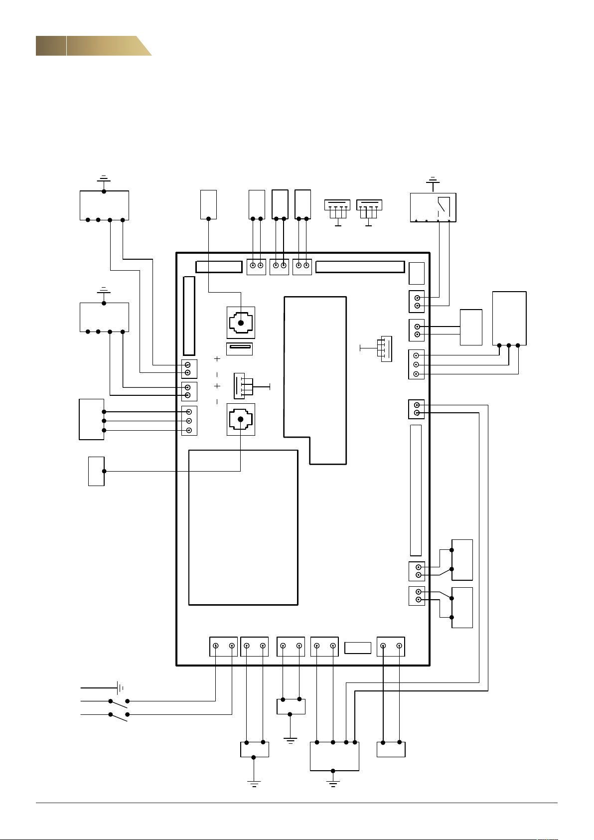
WIRING AND CONNECTION DIAGRAM
WIRING AND CONNECTION DIAGRAM, CONTROL CARD
Heat recovery unit RDKS - Technical manual
N
L
0 V
Extract air fan
N
L
0 V
Supply air fan
GND
RS485
B A
+10 V
+10 V
ISYteq Basic
70 69 68 67 66 65 64
Temp. outdoor
Temp. extract
5150494847
USB
A
Temp. supply
Moisture sensor
supply air
A
46
(accessory)
Ethernet board
Moisture sensor
extract air
B
B
L
N
Cooker hood
28 3732 33 34 3835 3613 14 15 16
27
sensor
2
CO
External alarm
(Volt free contact)
Output 0-10V
GND
+24 V
ISYteq Touch
L N PE
230 V
board
1 N
2 L
3 N
N
4 L
5 N
N
Pre-heater
L
6 L
L
7 N
N
8 L
L
Tacho
11 N
C
12 L
NO
200 mA
Max 24V,
MDI MDI
Timer 1 Timer 2
FläktGroup DC_9295GB_20190326_R5
We reserve the right to make changes without prior notice
Page 15
Heat recovery unit RDKS - Technical manual
Moisture barrier
Moisture barrier
Moisture barrier
Min thickness 10 cm.
Moisture barrier
Roof truss
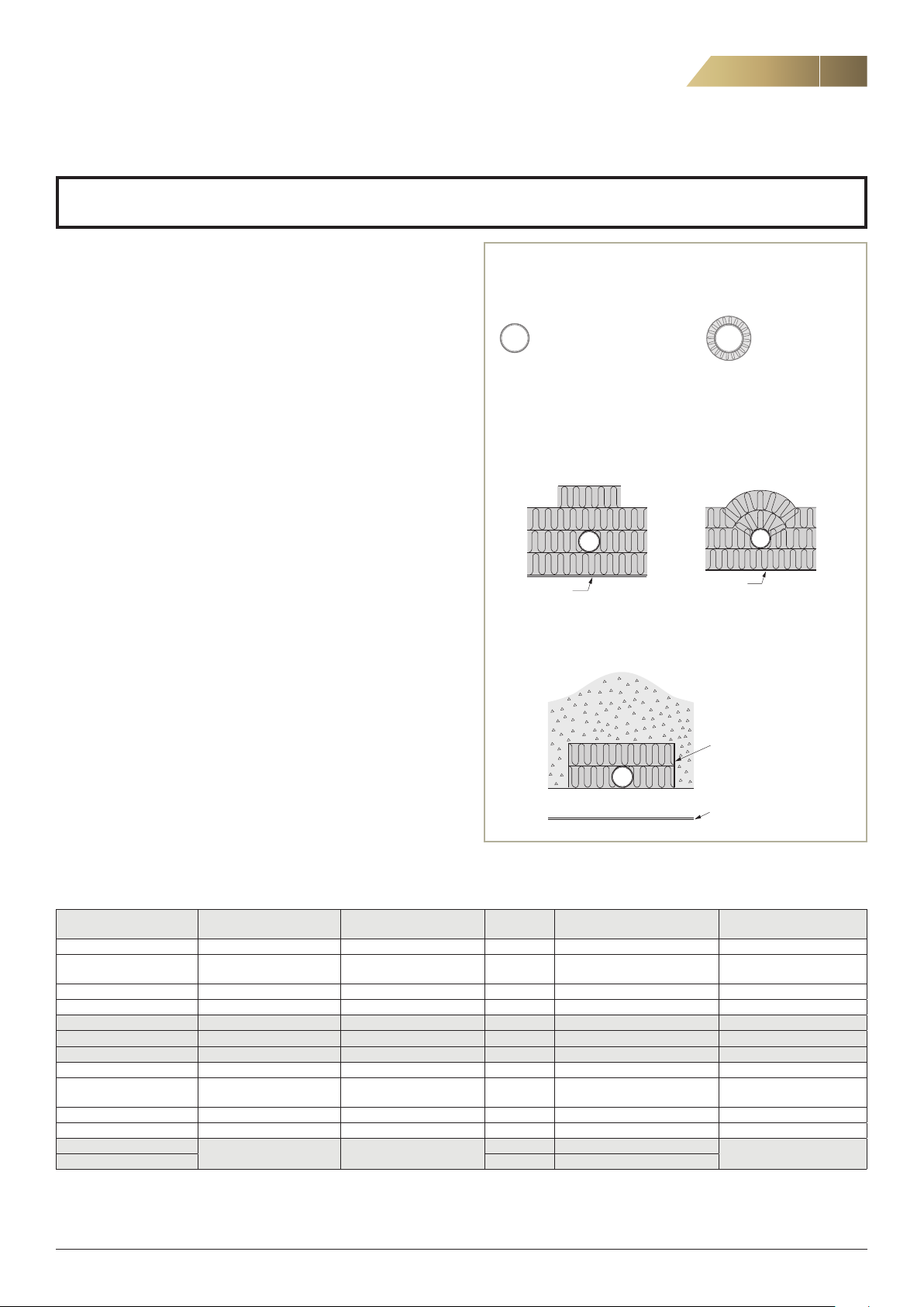
DUCT CONNECTION, DUCT INSULATION
Note! During installation, the instructions regarding unit installation and duct insulation must be adhered
to without deviation. Otherwise, there is a risk of condensation and moisture resulting in major damage.
15
DUCT CONNECTION
Exhaust air from the unit may only be connected to a ventilation
duct intended for this purpose. Connection must not be made to a
smoke or gas flue. In case of extract air ventilation in premises where
a smoke or gas flue is used (for instance, an open fireplace or heating
stove), an adequate supply air flow must be ensured A kitchen flue
must be installed in accordance with applicable regulations.
We recommend having a separate extract air device in the kitchen and
a boost damper with dense blades to ensure heat recovery from air in
kitchen.
DUCT INSULATION
In order for the installation of the unit to be effective, it is crucial that
the installation of the ventilation ducts in the unit, as well as the instal
lation of ducts through external walls containing insulation and vapour
barriers, roofs and joists, is executed in a professional manner. Other
wise there is a risk of condensation, resulting in moisture damage.
If older units are replaced, it is also necessary to inspect ducts and
duct insulation for damage and ensure they are of adequate quality.
Supply air ducts (T) and extract air ducts (F), i.e. ducts containing
warm air, which are located in unheated spaces, must be insulated.
The insulation should be installed externally and have a wind-proof
surface.
Outdoor air ducts (U) and exhaust air ducts (A), i.e. ducts filled with
cold air, which are located inside the building’s vapour barrier, must be
insulated and have a diffusion-proof (moisture-proof) surface. Given the
high degree of heat recovery achieved by the unit, the exhaust air also
gets very cold and must be thermally insulated. Moreover, ducts which
run alongside each other must have a common vapour barrier.
For designations of the various ducts, see figure 15 on previous page.
The wall on which the unit is to be installed must be well insulated.
-
DUCTS IN WARM SPACES (INDOORS)
The temperature of the air
in the duct is above +10 °C
Supply air ducts (T)
Extract air ducts (F)
No insulation
The temperature of the air
in the duct is below +10 °C
Outdoor air duct (U)
Exhaust air duct (A)
Supply air duct (T)
Fire protection
Extract air duct (F)
mesh mat 30 mm
with moisture-proof surface
DUCTS IN COLD SPACES
Supply air duct (T) Outdoor air duct (U)
Extract air duct (F) Exhaust air duct (A)
-
Moisture barrier
Moisture barrier
DUCTS IN LOOSE WOOL
The sheet must be bound
tightly to the duct.
Min thickness 10 cm.
Moisture barrier
Roof truss
Moisture barrier
RECOMMENDED INSULATION AND VAPOUR BARRIERS FOR DIFFERENT TYPES OF DUCTING
Ducting type
Exhaust air (flue)
In kitchen
Between joists and in attic Sheet metal Fire protection E15, Yes Fire protection E15, Only inside
Exhaust air (no flue) Sheet metal Mineral wool 25 mm Yes – –
Between joists and in attic Sheet metal Mineral wool 30 mm Ye s Mineral wool 30 mm Yes
From tumble dryer Sheet metal Mineral wool 30 mm No Mineral wool 100 mm No
Outdoor air
In kitchen
Between joists and in attic Sheet metal Mineral wool 60 mm Yes Inside building’s vapour barrier Only inside
Supply air
Extract air or equivalent.
Approved material and
location
Sheet metal, accessible for
inspection
Sheet metal, accessible for
inspection
Sheet metal No requirements
All figures in this table are recommended values which apply in central Sweden. Please check for local variations.
FläktGroup DC_9295GB_20190326_R5
Duct in a warm space
Insulation
Armaflex AF3, 19 mm Yes – –
mesh mat 30 mm mesh mat 50 mm building's vapour barrier
Armaflex AF3, 19 mm Yes – –
Vapour
barrier
Duct in a cold space Insulation Vapour barrier
Mineral wool 60 mm building's vapour barrier
Mineral wool at least 80 mm
We reserve the right to make changes without prior notice
No
Page 16
16
!
!
T
K
U
F
A
INSTALLATION OPTIONS AND DUCT DEFINITIONS
INTRODUCTION
If the unit is not installed immediately after delivery, it should be stored
well-protected under a roof in its original packaging. We recommend
that the unit always be lifted by two people. Protective gloves should be
worn.
Heat recovery unit RDKS - Technical manual
To prevent accidents and injury:
The unit must be connected to ducting and the door
must be closed before the power is switched on.
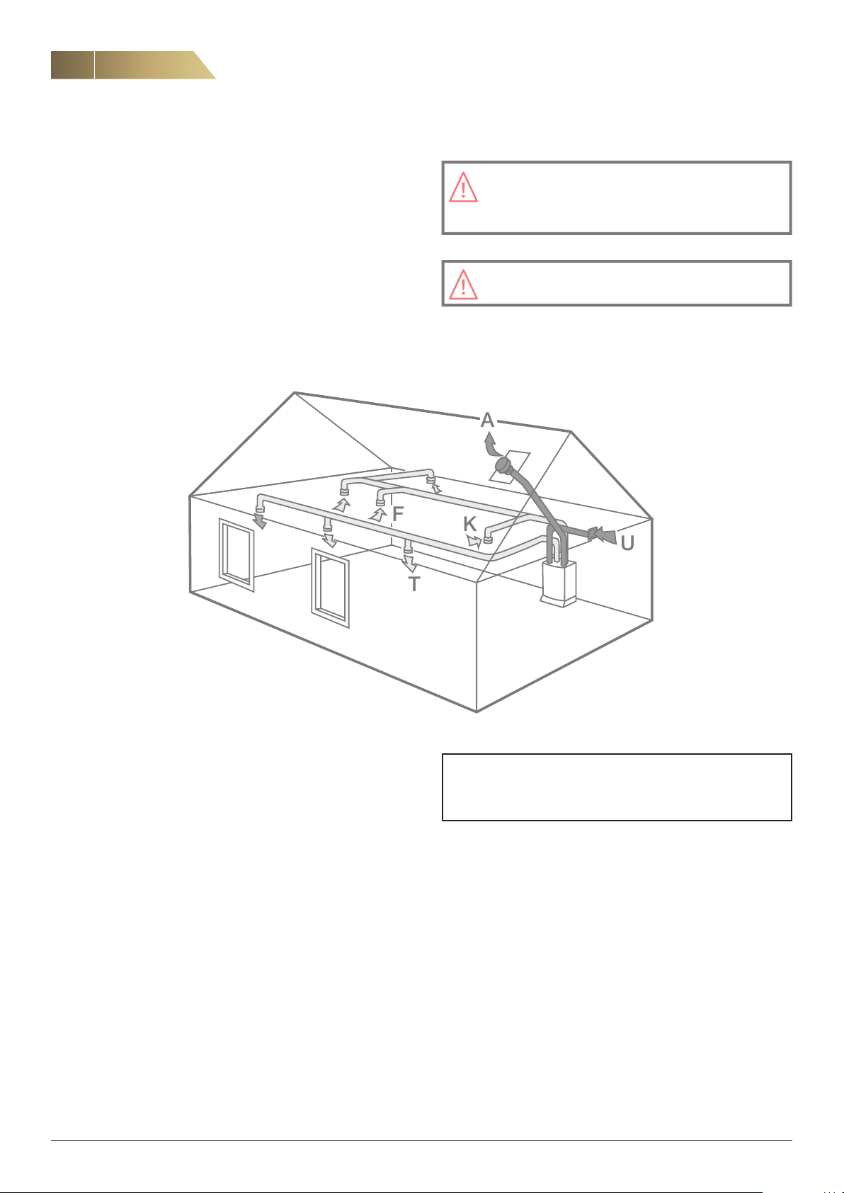
INSTALLATION OPTIONS
The unit should be positioned as shown in the ventilation drawing. If no
ventilation drawing is available, installation should be done according to
one of the installation options below. The unit is intended for installation
indoors in a warm space.
DUCT DEFINITIONS
The unit must be connected to an earthed power
outlet.
Figure 15. Duct definitions.
T = Supply air
F = Extract air
U = Outdoor air
A = Exhaust air
K = Extract air device in kitchen (not above cooker).
Ducts U and F should be increased to Ø125 mm as
soon as space allows after the unit.
FläktGroup DC_9295GB_20190326_R5
We reserve the right to make changes without prior notice
Page 17
Heat recovery unit RDKS - Technical manual
650
1)
30
50
600
100
210
1)
lower edge
of unit
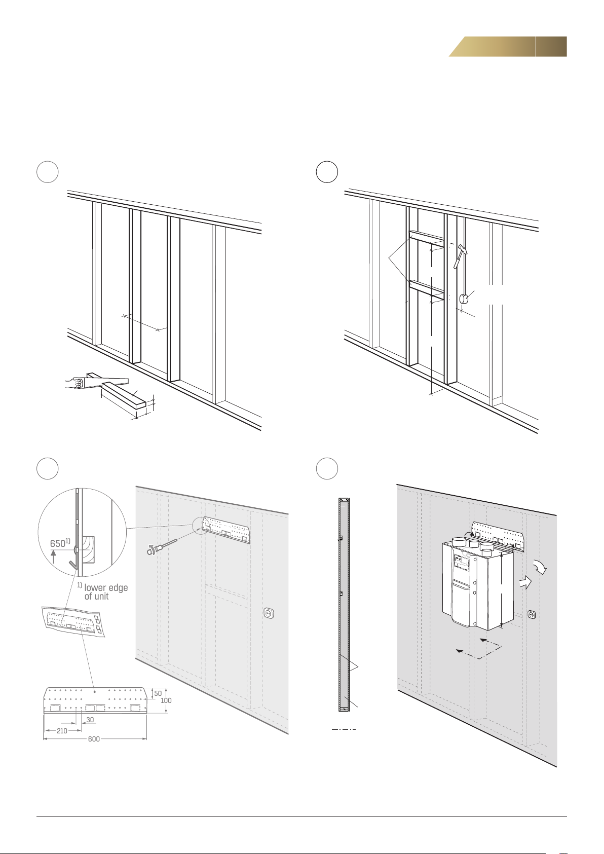
INSTALLATION OF UNIT WITH ACCESSORIES
17
If the unit is not installed immediately after delivery, it should be stored
well-protected under a roof in its original packaging. The unit is in
-
tended for installation indoors in a warm space, and may only be used
1
X
A x 2
X mm
25
50
while connected to ducts. We recommend that the unit be lifted into
place by two people wearing protective gloves.
2
A
*) Adapt to fit relevant cupboards.
NOTE! Distance from centre of upper
stud to lower edge of unit = 650 mm
50
600
50
1350*
The unit must be connected
to an earthed power outlet
max 200
3
4
70 69 6867 66 65 64
51
50
49
USB
48
47
A
46
1 N
2 L
3 N
4 L
B
5 N
6 L
7 N
8 L
28 37323334 383536
27
11 N
1516
1314
12 L
1
2
650
A
A
Plaster
Mineral wool
A
A
* Adapt to fit relevant cupboards.
FläktGroup DC_9295GB_20190326_R5
Note! It is important from a sound perspective that the wall on which
the unit is to be installed is well insulated.
We reserve the right to make changes without prior notice
Page 18
18
1
2
500
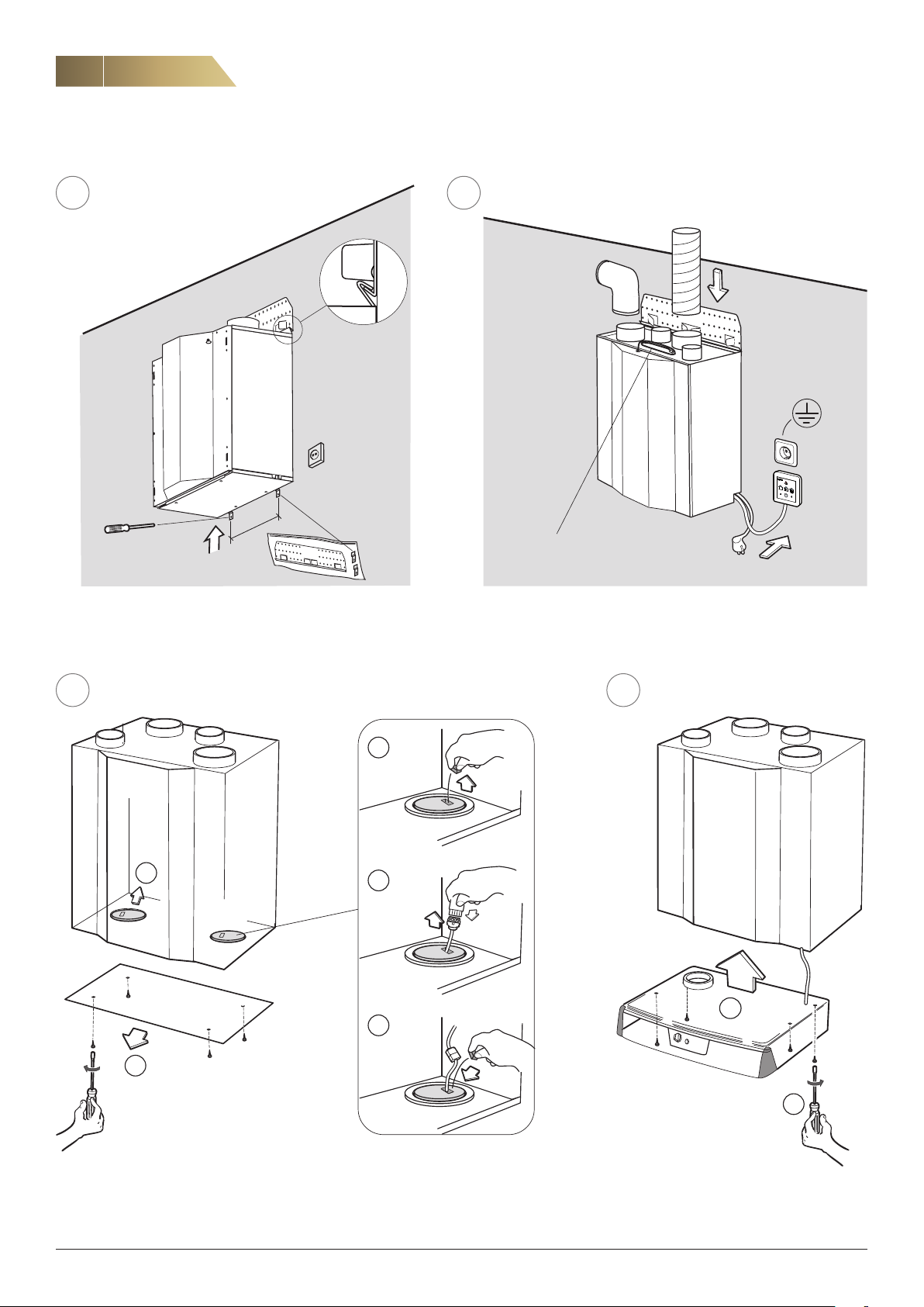
INSTALLATION OF UNIT WITH ACCESSORIES
Heat recovery unit RDKS - Technical manual
65
1
Make sure that the unit don’t fall of by folding out at least two of
the locking elements on the mounting plate, as well as securing the
unit at the bottom with the provided mounting angles.
7
3
RDKS
2
4
4.1
(If applicable)
2
Ethernet cable
NOTE! If an Ethernet cable is used, make sure it is long enough to allow the unit door to be opened without problems.
8
RDKS
4.2
1
The picture shows a unit with a right-hand configuration.
FläktGroup DC_9295GB_20190326_R5
6
5
7
We reserve the right to make changes without prior notice
Page 19
Heat recovery unit RDKS - Technical manual
2
Max 593
350
Overlap
ca 10 mm
Ceiling/Wall
Screw
Side panel
Front panel
Spacer
593
600
Kitchen
cabinet
INSTALLATION OF UNIT WITH ACCESSORIES
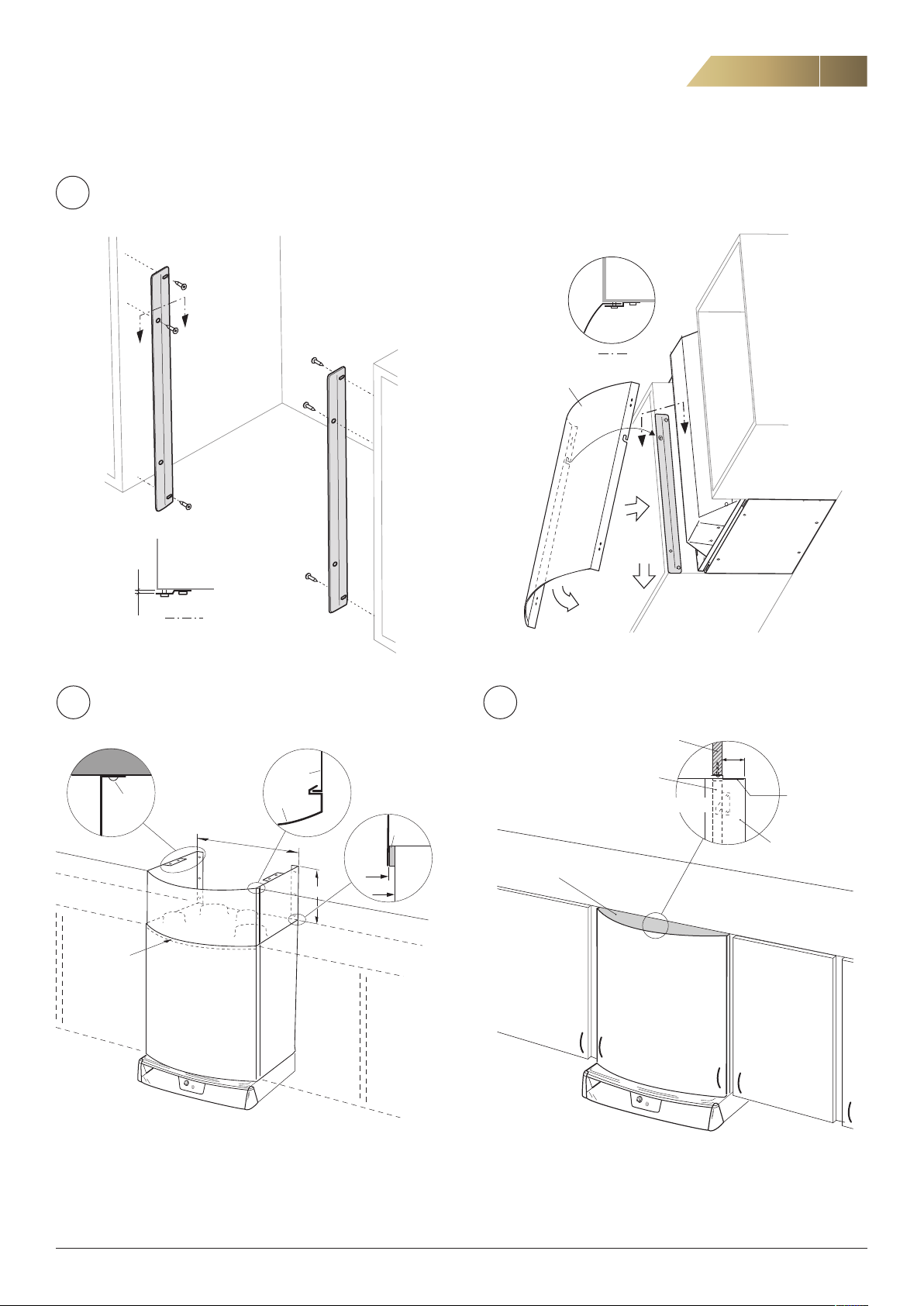
INSTALLATION OF FRONT COVER RDKZ-15-b-c-ddd-e (ACCESSORY)
9
9.1 9.2
A
A
19
B
B
≈ 3
A A
INSTALLATION OF EXTENSION UNIT TOWARDS THE
10
CEILING RDKZ-17 WITH FRONT COVER RDKZ-15 AND
SUSPENSION HOOKS RDKZ-16 (ACCESSORY)
Ceiling/Wall
Screw
Side panel
Front panel
Max 593
350
593
600
Spacer
Kitchen
cabinet
RDKZ-15
B
B
1
3
INSTALLATION OF FRONT COVER RDKZ-15 WITH
11
OVER-CABINET PANEL ABOVE KITCHEN CABINETS
Over-cabinet panel
(not included in delivery)
Unit hatch (15 mm)
Cover panel (included in RDKZ-14-b-0)
Section
1)
90
RDKR
Over-cabinet panel
Cover panel
Front cover
RDKZ-14
Overlap
ca 10 mm
An extension unit (kit) for the front cover is available to order. It is available in two
heights to ensure coverage all the way up to the ceiling (see figure above). It can be
adjusted to fit different cupboard depths and should be placed inside the front cover,
slightly overlapping. Note! The front cover must be installed with suspension hooks
in order to be able to fit the extension unit.
For dismantling instructions, see www.flaktgroup.com
FläktGroup DC_9295GB_20190326_R5
1)
The measurement 90 refers to the distance from the outside of the unit door to
the outer edge of the curve on the cover plate.
We reserve the right to make changes without prior notice
Page 20
20
1
2
INSTALLATION OF UNIT WITH ACCESSORIES
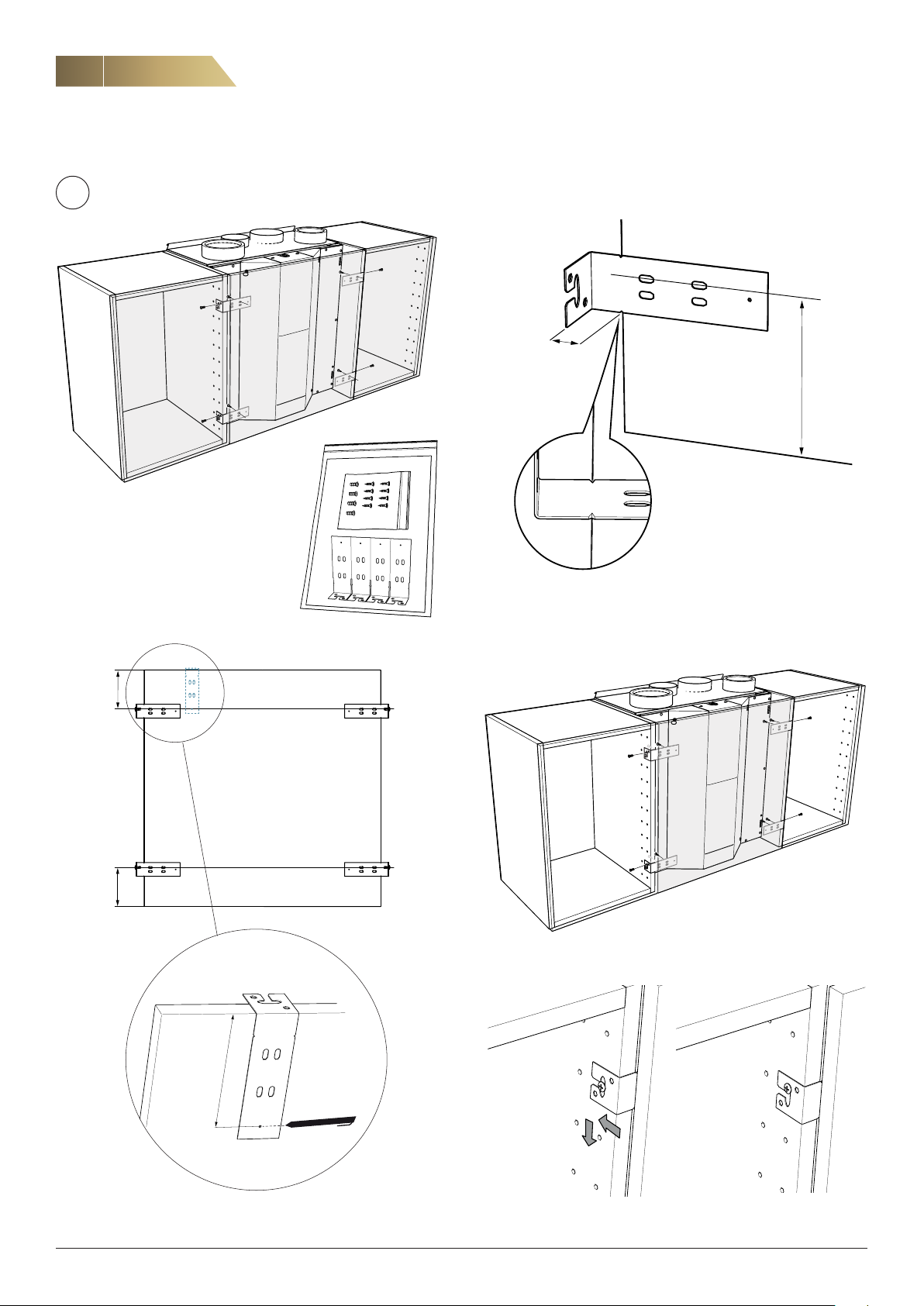
INSTALLATION OF MOUNTING KIT FOR KITCHEN CABINET DOOR IN FRONT OF THE UNIT RDKZ-18-1
12
19
Heat recovery unit RDKS - Technical manual
99
99
99
Mounting kit RDKZ-18-1
2. Determine the position of the brackets on the kitchen cabinet door
sideways through marking on the bracket, see the picture above.
3. Fit the brackets on the kitchen cabinet door using wood screws.
43
3
4
3
4
3
4
4. Fit the 4 set screws in the front hollow row of the side cabinets.
99
1. Determine and mark the position of the bracket in the height of the
kitchen cabinet using the bracket.
FläktGroup DC_9295GB_20190326_R5
5. Hook on the cover, tighten the set screws if necessary.
We reserve the right to make changes without prior notice
Page 21
Heat recovery unit RDKS - Technical manual
!
!
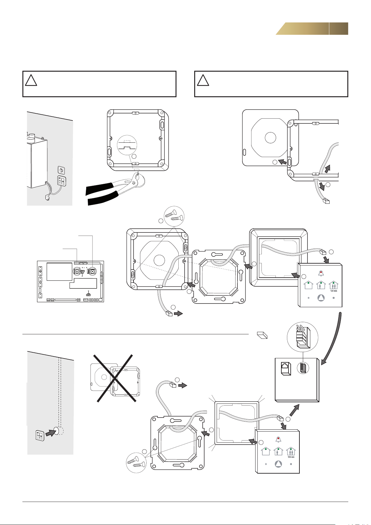
RDKZ-41-1 CONTROL PANEL ISYteq BASIC - INSTALLATION AND CONNECTION
21
The power supply must be switched off while
control panel RDKZ-41-1 is being installed and
dismantled.
ISYteq BASIC
RDKZ-41-1
ISYteq TOUCH 3.5
RDKZ-41-3
1 N
2 L
3 N
4 L
5 N
6 L
7 N
8 L
11 N
12 L
70 69 6867 66 65 64
A
Ethernetkort
(tillbehör)
27
28 3732 33 34 3835 361314 15 16
51
50
USB
49
48
47
46
B
Make sure that the control cable is correctly connected to the control card before switching on the
power supply.
1
4
6
5
3
2
7
CLICK
8
Control card
9
To unit for connection.
= Jumper
1
To unit for connection.
back
rear side
4
3
5
2
CLICK
FläktGroup DC_9295GB_20190326_R5
We reserve the right to make changes without prior notice
Page 22
22
Heat recovery unit RDKS - Technical manual
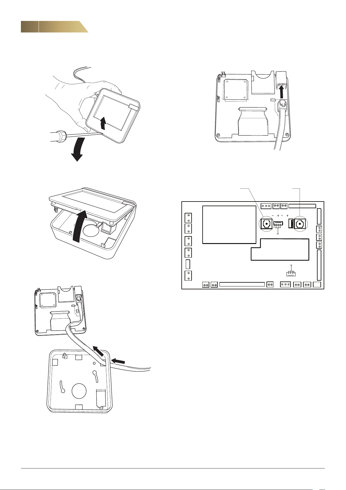
RDKZ-41-3 ISYteq TOUCH 3.5 CONTROL PANEL - INSTALLATION AND CONNECTION
5. Connect the cable to the back of the display as shown above. NOTE!
1. Open the control panel using a screwdriver.
Do not touch the electronics.
Push the display back into the enclosure.
2. Lift the display out of the enclosure.
ISYteq TOUCH 3.5
RDKZ-41-3
1 N
2 L
3 N
4 L
5 N
6 L
7 N
8 L
11 N
12 L
ISYteq BASIC
RDKZ-41-1
70 69 68 67 66 65 64
A
Ethernet card
(accessory)
27
28 3732 33 34 3835 3613 14 15 16
51
USB
B
50
49
48
47
46
6. Check that the control cable is correctly connected to the control
card before switching on the power supply.
3. Push the connection cable through a suitable hole and if needed
make an outlet for the cable on side of the cover.
4. Mount the enclosure directly on the wall or using the screws in a
junction box.
FläktGroup DC_9295GB_20190326_R5
We reserve the right to make changes without prior notice
Page 23
Heat recovery unit RDKS - Technical manual
ADJUSTMENT, COMMISSIONING (FOR INSTALLER AND SERVICE PERSONNEL)
23
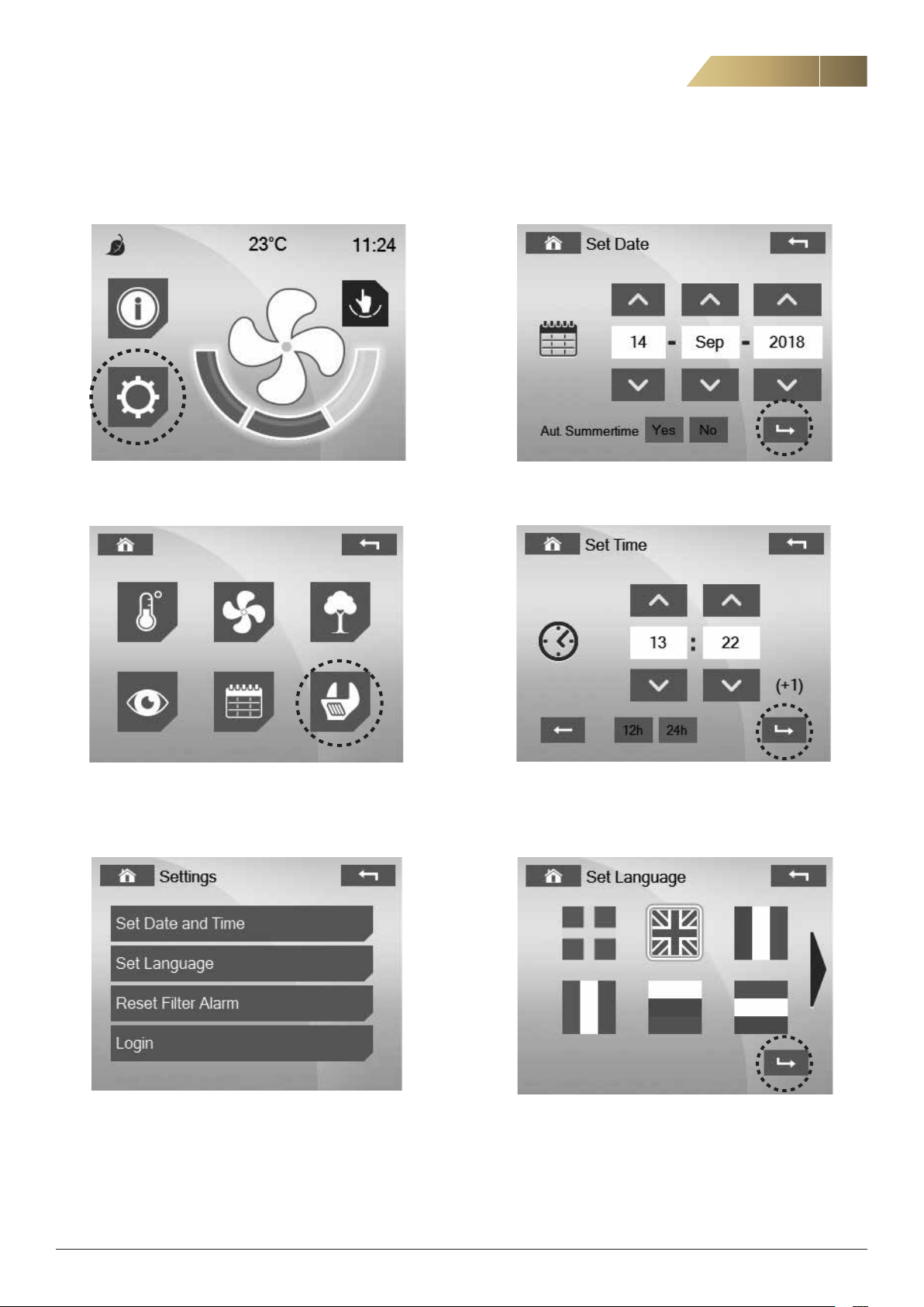
SETTINGS
To enter the “Settings” menu:
1. Press the gear cog button.
DATE / TIME
1. Set the date and continue by pressing “Confirm”.
2. Press the spanner button.
3. In this menu you can set the date, time and language. There is also
the option of resetting the filter alarm in advance. Installers and ser
vice personnel can log in and access additional parameters.
2. Set the time. Press “Confirm”.
SELECT LANGUAGE
1. Press the appropriate language flag. Press “Confirm”.
-
FläktGroup DC_9295GB_20190326_R5
We reserve the right to make changes without prior notice
Page 24
24
LOGIN, SETTINGS
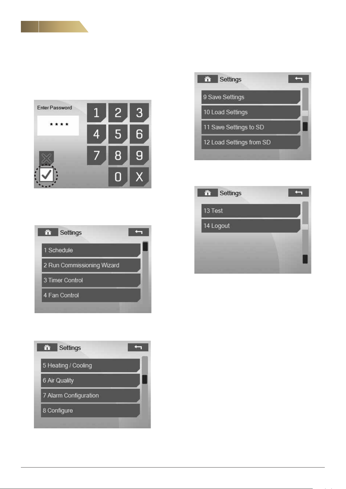
LOGIN
Installers and service personnel must log in to access “Settings”.
The default (preset) password is 0000. This password can be
changed.
Heat recovery unit RDKS - Technical manual
1. Enter the correct password. Press “Confirm”. Use, for instance, the
back of a pencil for greater precision.
SETTINGS FOR INSTALLER AND SERVICE PERSONNEL
For adjustment of fans, see page 24.
For other settings, see parameter list on page 28.
FläktGroup DC_9295GB_20190326_R5
We reserve the right to make changes without prior notice
Page 25
Heat recovery unit RDKS - Technical manual
F T
A U
T F
U A
ADJUSTMENT
25
INTRODUCTION
Adjustment of air flow and temperature may only be carried out by an
installation engineer or service personnel. During adjustment, use the
ISYteq Touch 3.5 control panel (accessory).
Wrongly adjusted air flows may result in increased
energy consumption and damage to the building.
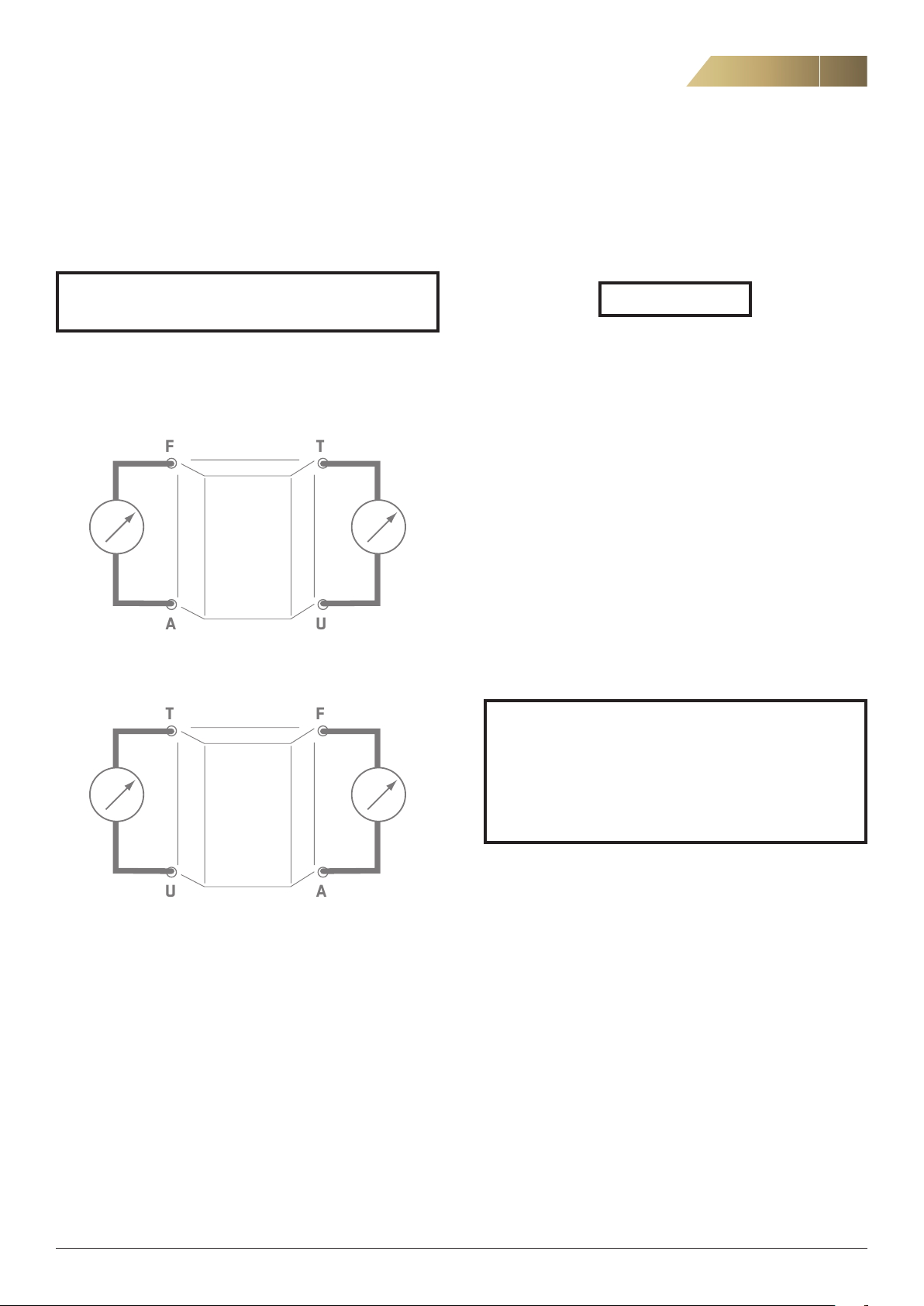
AIRFLOW ADJUSTMENT
The speed of the fans is adjusted independently of each other.
The picture shows an RDKS-1 unit.
The picture shows an RDKS-2 unit.
AIRFLOW CALCULATION
The unit is equipped with four measurement points as per figure 16
above. Measuring the pressure difference, Dp
gives the total supply air and extract air flows. The air flow q in l/s is
determined using the following formula:
in Pa over the impeller
m
q = 0.73 x Dpm
where Dpm = measured pressure in point T – measured pressure in
point U
or:
where Dp
point A
PLANNING ADVICE
In a rotary heat exchanger it is not possible to completely eliminate
leakage between supply air and extract air. Air leakage at the seals is
minimised by keeping the pressure difference between the supply air
and extract air ducts as small as possible.
Also check the pressure balance between supply air and extract air.
Lower pressure on the supply air side can result in the transfer of
moisture and odour. This is especially important if Forced mode is
used.
The pressure at point T should be higher than at point F.
The pressure at point U should be higher than at point A.
= measured pressure in point F – measured pressure in
m
T = Supply air F = Extract air
U = Outdoor air A = Exhaust air
NOTE! Flow deviations of up to 25% may occur when
this measurement method is used on a unit with a
rotary heat exchanger.
The measured flow values should only be regarded as
indicative. Always perform control measurement in the
supply and extract air devices
.
FläktGroup DC_9295GB_20190326_R5
We reserve the right to make changes without prior notice
Page 26
26
CONTROL PANEL OPERATION, COMMISSIONING
ADJUSTMENT
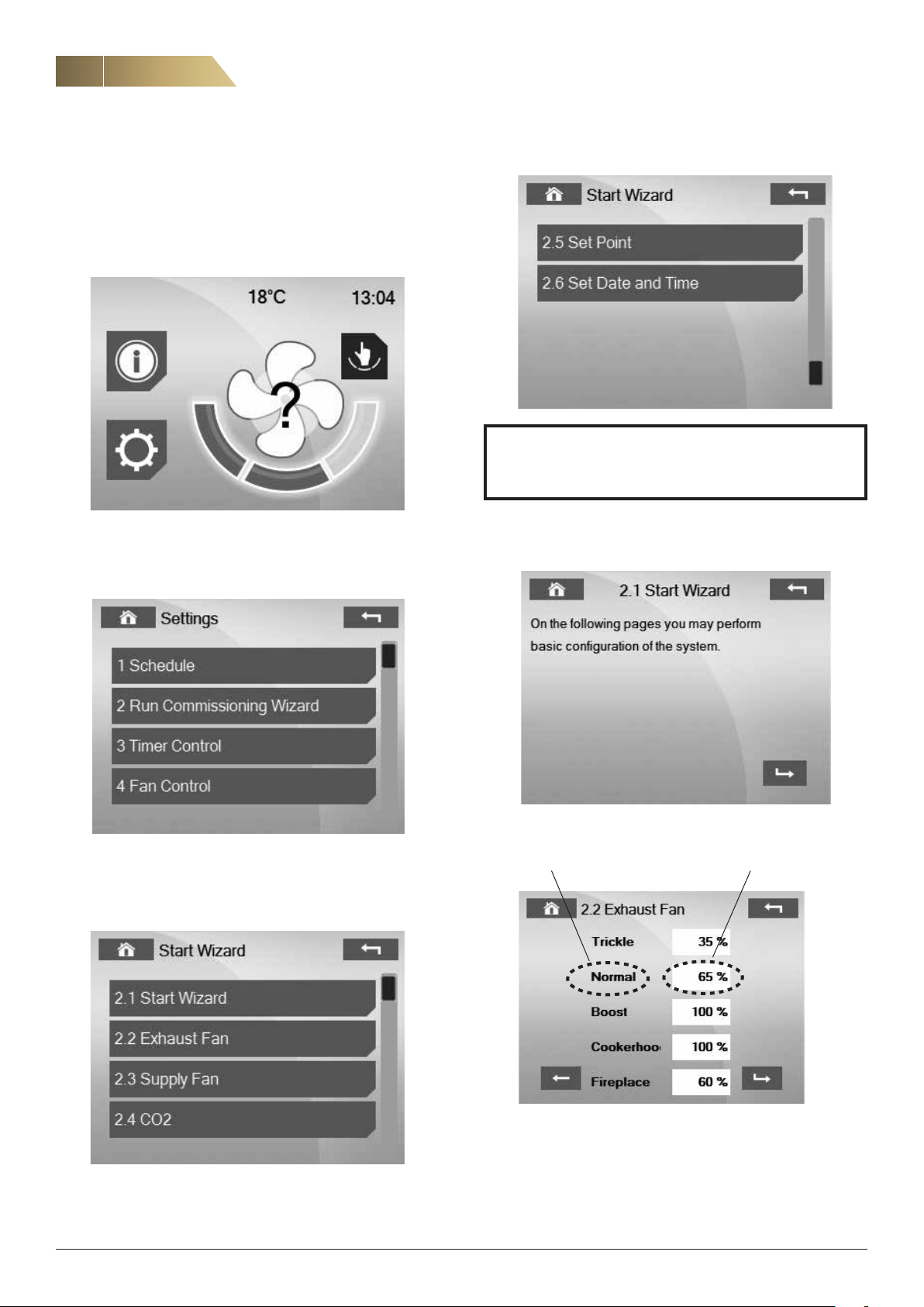
There are two ways to enter the adjustment menu.
1. The first is to press the question mark on the start screen. The
question mark will not be shown if the menu has been opened pre
viously.
Heat recovery unit RDKS - Technical manual
-
The unit can be ordered with two different configurations:
Standard – set the fan speed in % of max speed CO
the desired CO
level
2
control – set
2
2. The second is to go to Menu/Settings/Login and select
“2 Adjustment”.
Press “2.1 Start” for a step-by-step guide through the settings required
for adjustment. To change a single value, go directly to a specific
menu.
STANDARD
Option 1 Option 2
FläktGroup DC_9295GB_20190326_R5
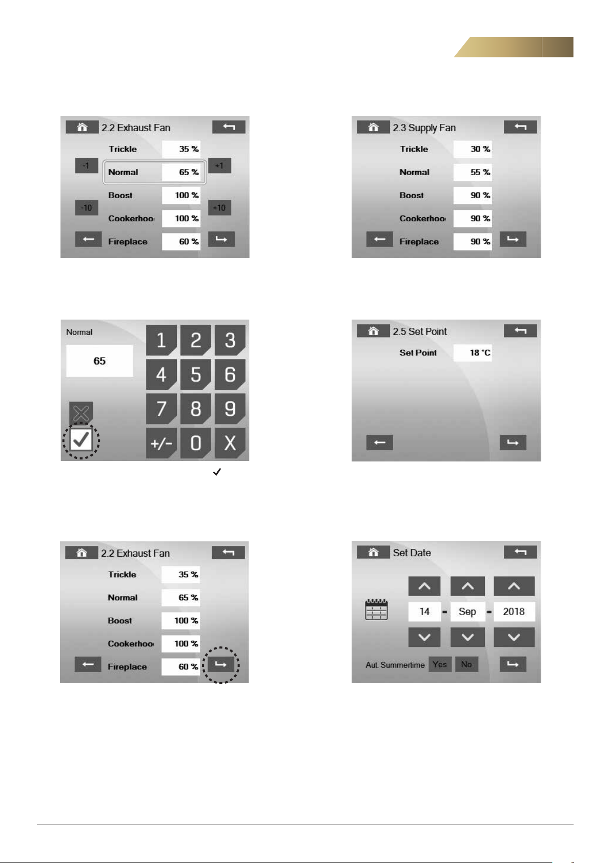
The speeds for each operating mode can be changed in two ways:
Option 1 - Press the name
Option 2 - Press the value
We reserve the right to make changes without prior notice
Page 27
Heat recovery unit RDKS - Technical manual
CONTROL PANEL OPERATION, COMMISSIONING
27
Option 1 - Use the ± buttons.
Option 2 - Enter the desired value, confirm with .
Configure the settings for the supply air fan in the same way.
Here you set the desired supply air temperature (setpoint). Note:
This value is not to be confused with the desired indoor tempera
ture, which is managed by the domestic heating system. The
recommended setpoint is 16–19 °C. The factory setting is 18 °C.
-
After configuring the settings, press “Confirm” and continue to the
next step.
FläktGroup DC_9295GB_20190326_R5
We reserve the right to make changes without prior notice
Page 28
28
CONTROL PANEL OPERATION, COMMISSIONING
Heat recovery unit RDKS - Technical manual
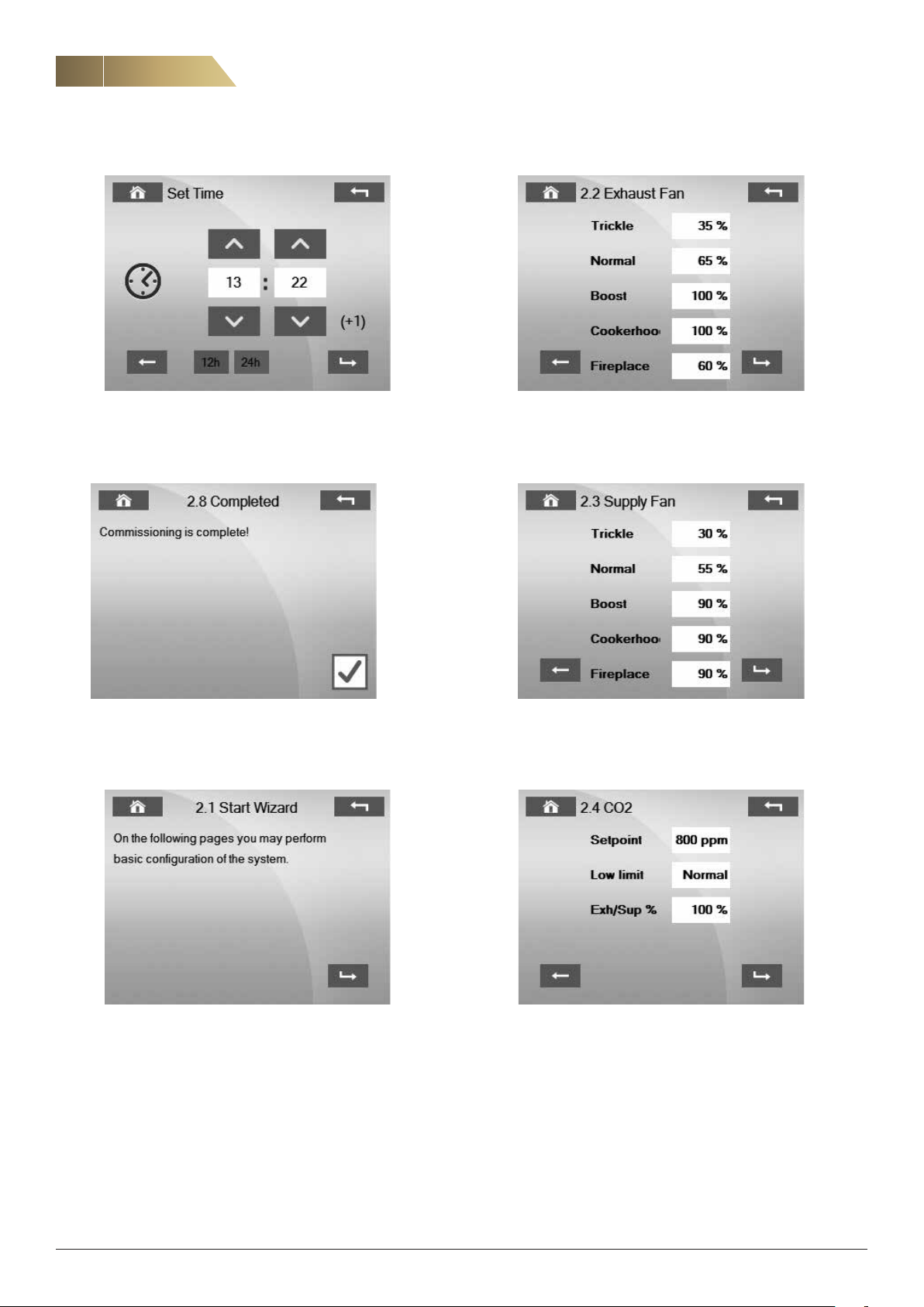
CO2 control is only active at normal speed. At low and high speed, set
the fan speed in % of max. speed.
To complete the adjustment, click the brown check mark.
CO2 CONTROL
1. Set the desired CO
2. Choose the minimum limit.
setpoint.
2
This specifies whether the minimum limit should be low or normal
speed. The speed cannot go below this value.
3. Set the relationship between the extract air and the supply air. The
extract air is the master and the supply air is the slave.
FläktGroup DC_9295GB_20190326_R5
We reserve the right to make changes without prior notice
Page 29
Heat recovery unit RDKS - Technical manual
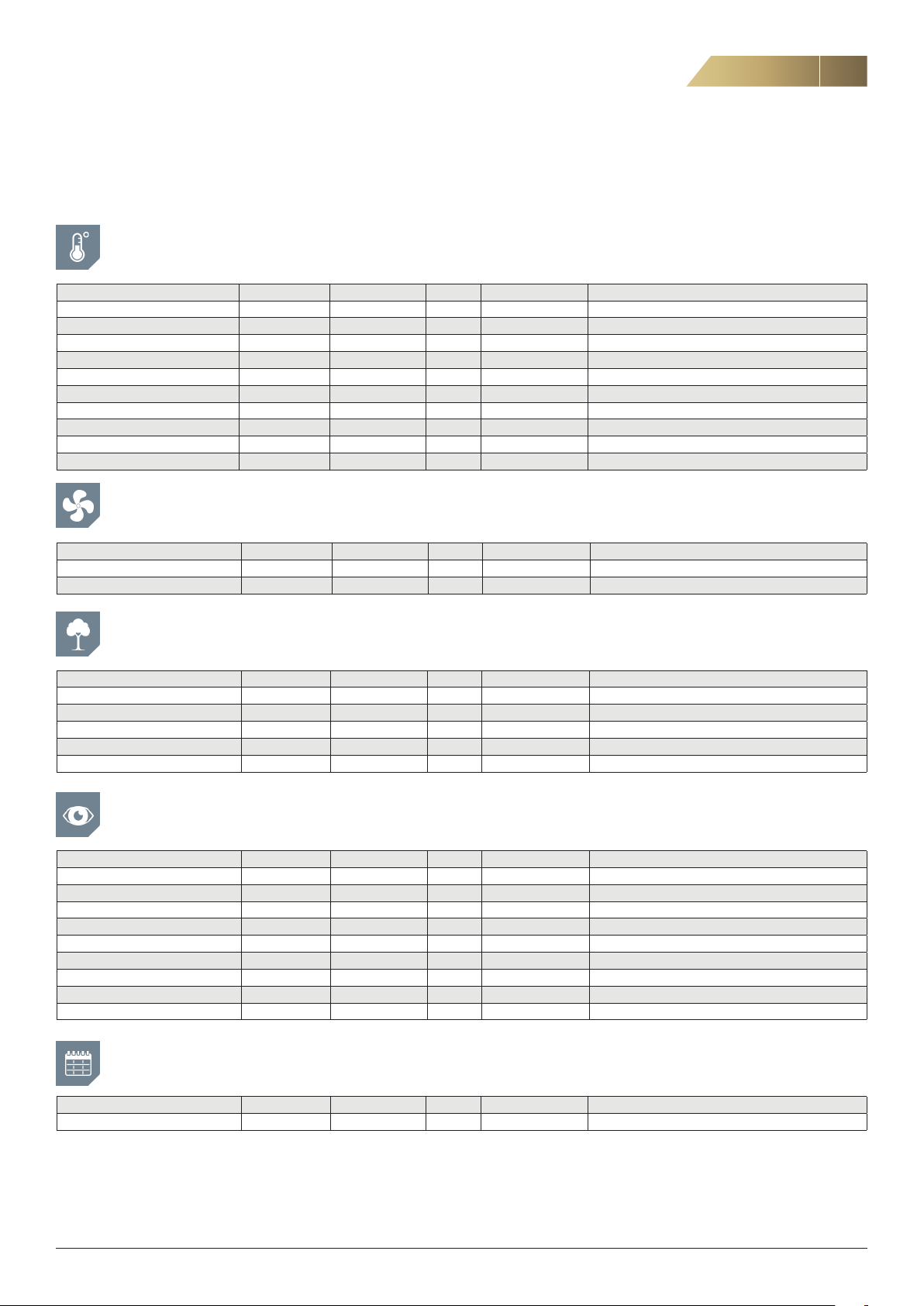
PARAMETER LIST
Note that incorrect parameter settings can cause moisture problems, operational disruption and other types of malfunction.
For this reason, the settings must be configured by suitably qualified professionals.
TEMPERATURES
29
Parameter Type of value
Supply air temperature L -40-100 °C –
Outdoor air temperature L -40-100 °C –
Extract air temperature L -40-100 °C –
Setpoint L/S 15-35 °C 18 Desired supply air temperature
Summer / Winter mode L Summer / Winter – –
Output signal Postheater L 0-100 % – Option
Output signal Preheater L 0-100 % – Option
Output signal Rotor L 0-100 % –
Output signal Cooling L 0-100 % – Not applicable to domestic ventilation
Control mode / Current setpoint L 15-35 °C –
1)
Range Unit Standard value Comment
FANS
Parameter Type of value
Supply air fan speed L 0 or 30–100 % –
Extract air fan speed L 0 or 30–100 % –
1)
Range Unit Standard value Comment
AIR QUALITY
Parameter Type of value
Relative humidity Supply air L 0-100 % RH –
Relative humidity Extract air L 0-100 % RH –
Moisture active L Yes / No – – Moisture control active or inactive
level L 0-2000 ppm – Current CO2 level in extract air
CO
2
Setpoint CO
2
1)
L 0-2000 ppm 800
Range Unit Standard value Comment
SYSTEM OVERVIEW
Parameter Type of value
Software version control panel L – – –
Bootloader version control panel
Software version control card L – – –
Bootloader version control card L – – –
Unit type L – – Domestic
IP Octet 1 L 0-255 – – Current IP address, accessory
IP Octet 2 L 0-255 – –
IP Octet 3 L 0-255 – –
IP Octet 4 L 0-255 – –
1)
L – – –
Range Unit Standard value Comment
TIME SCHEDULES
Parameter Type of value
Time schedules L – – – Activated time channels, read-only
1)
L/S = Editable value, L = Read-only value
FläktGroup DC_9295GB_20190326_R5
1)
Range Unit Standard value Comment
We reserve the right to make changes without prior notice
Page 30

30
PARAMETER LIST
SETTINGS
Heat recovery unit RDKS - Technical manual
Parameter Type of value
Date / Time L/S – – –
Select language L/S – – Swedish
Reset filter alarm L/S – – – For resetting alarm in advance
Login L/S 0000-9999 – 0000 For installer and service personnel
Settings For installer and service personnel
1. Time schedules Not applicable to domestic ventilation
2. Adjustment See page 24.
3. Timer function See separate document
4. Fans
4.1 Fan settings
Automatic return forced mode L/S Yes / No – Ye s
Forcing time L/S 0-9999 min 120
Start delay L/S 0-32767 s 10
Rundown L/S 0-32767 s 0 Not applicable to domestic ventilation
Heating stove time L/S 0-360 min 30 Reverts from heating stove mode after set time.
4.2 Pressure / Flow – – – – Not applicable to domestic ventilation
5. Heating / Cooling
5.1 Preheater Option
Preheater L/S Yes / No Yes
Setpoint preheater L/S -25-10 °C -12
Filter heating L/S Yes / No No Not applicable to domestic ventilation
1)
Range Unit Standard value Comment
Extract air fan and rotor start immediately, supply air fan
starts after set time delay
5.2 Heating / Cooling – – – –
Control mode L/S 1-2 1 Not applicable to domestic ventilation
Cooling sequence L/S Yes / No No Not applicable to domestic ventilation
DX cooling L/S Yes / No No Not applicable to domestic ventilation
Block heating in summer L/S Yes / No Yes
Postheater L/S On / Off On
Relative or absolute value L/S Rel / Abs – Rel
5.4 Defrosting
Temperature setpoint defrosting L -25-10 °C -10
5.5 Cooling recovery
Cooling recovery L/S Yes / No – Yes
Temperature difference (outdoor
air-extract air)
Setpoint humidity L/S 0-100 % 50
5.6 Summer / Winter mode
Summer/winter mode L Summer / Winter – –
Automatic / Manual mode L/S
Manual Winter / Summer L/S Summer / Winter – Winter
5.8 Night setback
Activate night setback L/S Yes / No – No
Start time L/S
Stop time L/S
Temperature difference L/S 0 - 20 °C 3 Setpoint reduced during certain times
1
) L/S = Editable value, L = Read-only value
L/S 0-15 °C 2
Auto / Manual
00.00 - 23.59
00.00 - 23.59
– Auto
– 22.00
– 06.00
Used for setpoint in time channels
FläktGroup DC_9295GB_20190326_R5
We reserve the right to make changes without prior notice
Page 31

Heat recovery unit RDKS - Technical manual
PARAMETER LIST
31
Parameter Type of value
1)
Range Unit Standard value Comment
6. Air quality
6.1 CO
control
2
CO
2
Setpoint CO
2
L/S Yes / No – No
L/S 0-2000 ppm 800
P-band L/S 0-2000 ppm 800
Int action time L/S 0-9999 s 600
ppm at 0 V L/S 0-9999 ppm 0
ppm at 10 V L/S 0-9999 ppm 2000
Min. limit CO
2
L/S Low / Normal – Normal
6.2 Moisture control
Moisture control L/S Yes / No – Yes
Absolute humidity supply air L 0-100 g/kg –
Absolute humidity extract air L 0-100 g/kg –
7. Alarm management
7.1 Alarm settings
Filter alarm time L/S 0-600 days 180 Set to 0 to deactivate filter alarm
Summation alarm output A+B L/S Yes / No – Ye s
Activate temperature alarm L/S Yes / No – Yes
Temperature alarm L/S -10–+10 °C 5
Activate rotor belt test L/S Yes / No – No Function not imported
Tacho signal alarm L/S Yes / No – Ye s
7.2 Alarm categories
Fire alarm L/S A/B – A External function
Sensor error supply air L/S A/B – A
Sensor error outdoor air L/S A/B – A
Sensor error extract air L/S A/B – A
Sensor error frost protection L/S A/B – B Not applicable to domestic ventilation
Sensor error defrosting L/S A/B – B Not applicable to domestic ventilation
Sensor error AI10 L/S A/B – B Not applicable to domestic ventilation
Filter alarm L/S A/B – B
Fan monitor, supply air L/S A/B – B Not applicable to domestic ventilation
Fan monitor, extract air L/S A/B – B Not applicable to domestic ventilation
Pressure monitor heat exchanger L/S A/B – B Not applicable to domestic ventilation
Rotor monitor L/S A/B – A
Filter monitor, supply air L/S A/B – B Not applicable to domestic ventilation
Filter monitor, extract air L/S A/B – B Not applicable to domestic ventilation
Overheating electric heater L/S A/B – B Not applicable to domestic ventilation
Circ. pump heating L/S A/B – B Not applicable to domestic ventilation
Frost protection L/S A/B – B Not applicable to domestic ventilation
Summation alarm cooling L/S A/B – B Not applicable to domestic ventilation
Circ. pump cooling L/S A/B – B Not applicable to domestic ventilation
Temperature alarm L/S A/B – A
Rotor belt alarm L/S A/B – A Function not imported
7.3 Alarm delays
Fire alarm L/S 0-9999 s 2 External function
Sensor error supply air L/S 0-9999 s 5
Sensor error outdoor air L/S 0-9999 s 5
Sensor error extract air L/S 0-9999 s 5
Sensor error frost protection L/S 0-9999 s 5 Not applicable to domestic ventilation
Sensor error defrosting L/S 0-9999 s 5 Not applicable to domestic ventilation
Sensor error AI10 L/S 0-9999 s 5 Not applicable to domestic ventilation
Fan monitor, supply air L/S 0-9999 s 120 Not applicable to domestic ventilation
Fan monitor, extract air L/S 0-9999 s 120 Not applicable to domestic ventilation
Rotor monitor L/S 0-9999 s 2 Not applicable to domestic ventilation
Filter monitor, supply air L/S 0-9999 s 60 Not applicable to domestic ventilation
Filter monitor, extract air L/S 0-9999 s 60 Not applicable to domestic ventilation
Overheating electric heater L/S 0-9999 s 2 Not applicable to domestic ventilation
Circ. pump heating L/S 0-9999 s 2 Not applicable to domestic ventilation
Frost protection L/S 0-9999 s 2 Not applicable to domestic ventilation
Summation alarm cooling L/S 0-9999 s 2 Not applicable to domestic ventilation
Circ. pump cooling L/S 0-9999 s 2 Not applicable to domestic ventilation
Temperature alarm L/S 0-9999 min 10
Rotor belt alarm L/S 0-9999 s 60 Function not imported
1
) L/S = Editable value, L = Read-only value
FläktGroup DC_9295GB_20190326_R5
We reserve the right to make changes without prior notice
Page 32
32
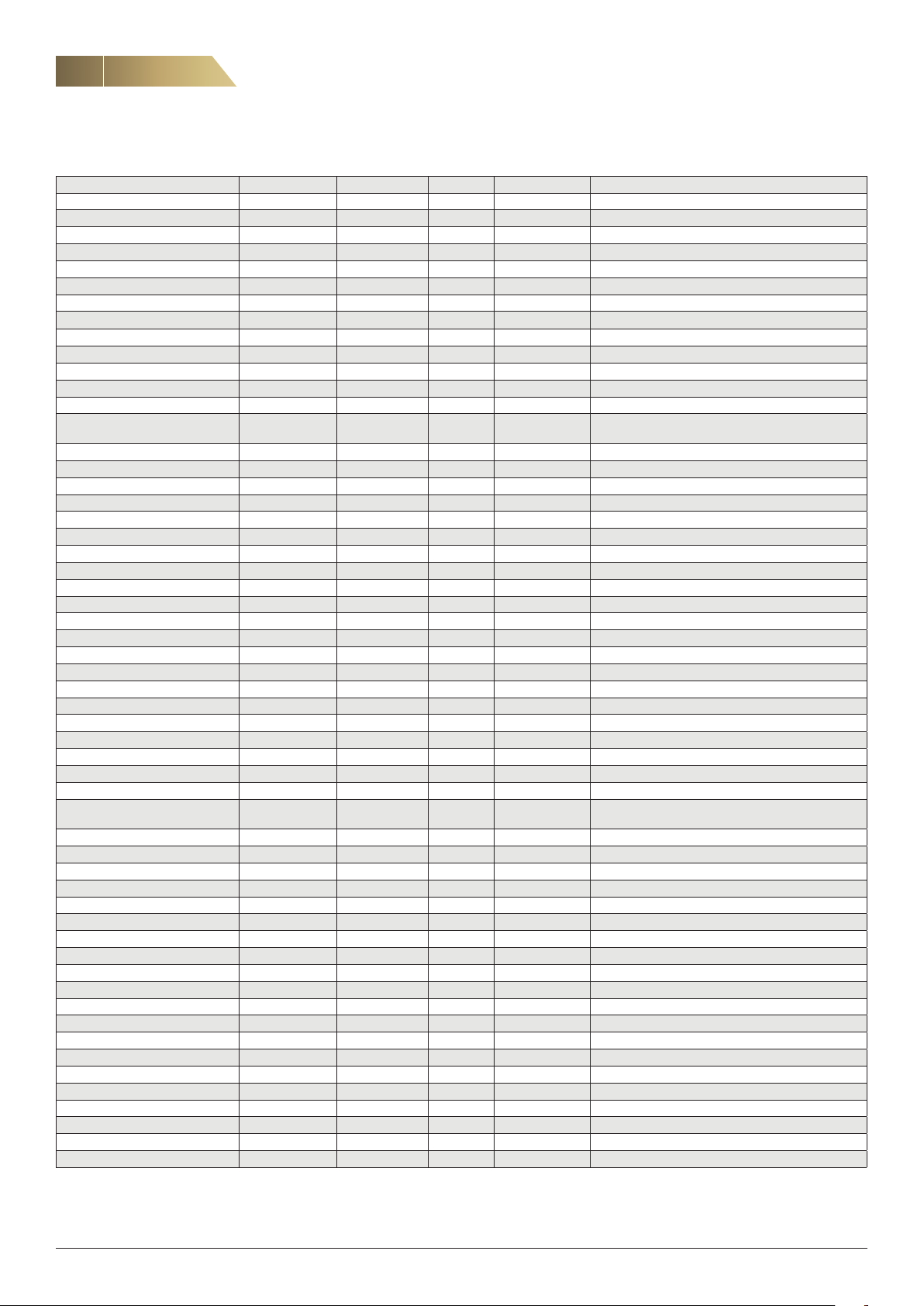
PARAMETER LIST
Heat recovery unit RDKS - Technical manual
Parameter Type of value
7.4 Contact functions
DI1 Timer input 1 L/S NO/NC – NO
DI2 Timer input 2 L/S NO/NC – NO
DI3 Rotation monitor L/S NO/NC – NO Not applicable to domestic ventilation
DI4 Pressure monitor defrosting L/S NO/NC – NO Not applicable to domestic ventilation
DI5 Fan / Filter monitor TF L/S NO/NC – NO Not applicable to domestic ventilation
DI6 Fan / Filter monitor FF L/S NO/NC – NO Not applicable to domestic ventilation
DI8 Fire alarm L/S NO/NC – NO External function, should be changed to NC during use
DI9 Cooker hood connector L/S NO/NC – NO Not applicable to domestic ventilation
DI7 Alarm heating L/S NO/NC – NO Not applicable to domestic ventilation
DI10 Alarm cooling L/S NO/NC – NO Not applicable to domestic ventilation
8. Configuration
8.1 IP address L/S
IP address L/S – – –
Subnet mask L/S – – –
Gateway L/S – – –
8.2 Menu config.
Log to USB L/S Yes / No – No Only for troubleshooting
Unit type L – – Domestic
Auto logout time L/S 0-32767 min 10
Threshold value heating L/S 0-100 % 0 For installer andservice personnel service personnel
Threshold value cooling L/S 0-100 % 0 For installer andservice personnel service personnel
Threshold value recovery L/S 0-100 % 0 For installer andservice personnel service personnel
Threshold value external fan L/S 0-100 % 5 For installer andservice personnel service personnel
1)
Static / Dynamic
Range Unit Standard value Comment
– Dynamic
Static = Manual setting
Dynamic = Automatic assignment of IP address via DHCP
8.3 Screen saver
Screen saver L/S On / Off – On
Time L/S – min 10
8.4 Modbus
Modbus slave address BMS L/S 0-255 – 2
Baud rate L/S 9.6, 19.2, 38.4 – 19.2
Parity L/S
Data bit L/S 7.8 – 8
Stop bit L/S 1.2 – 1
8.5 Mac address
Mac address L – – –
8.6 Reset
8.6.1 Soft reset
Reset – – – – All values are reset except adjusted values and setpoints
8.6.2 Factory reset
Reset – – – – All values are reset
8.7 Password
Automatic logout L/S Yes / No – Ye s
Password 1 L/S – – – Used to change the password
8.8 Om
Software HMI – – –
Software control card L – – –
Bootloader version L – – –
1)
L/S = Editable value, L = Read-only value
no parity, even,
odd
– None
FläktGroup DC_9295GB_20190326_R5
We reserve the right to make changes without prior notice
Page 33

Heat recovery unit RDKS - Technical manual
PARAMETER LIST
33
Parameter Type of value
9. Save values Saves adjusted values in control panel, max. 5 values
Memory 1 – – – –
Memory 2 – – – –
Memory 3 – – – –
Memory 4 – – – –
Memory 5 – – – –
10. Upload values Uploads saved adjusted values from control panel
Memory 1 – – – –
Memory 2 – – – –
Memory 3 – – – –
Memory 4 – – – –
Memory 5 – – – –
11. Save to SD Copies saved values to an SD card
Memory 1 – – – –
Memory 2 – – – –
Memory 3 – – – –
Memory 4 – – – –
Memory 5 – – – –
12. Load from SD Copies saved values from an SD card
Memory 1 – – – –
Memory 2 – – – –
Memory 3 – – – –
Memory 4 – – – –
Memory 5 – – – –
1)
Range Unit Standard value Comment
– – – –
13. Test function Only for troubleshooting
13.1 Inputs – – – –
13.2 Outputs – – – –
14. Log out
1)
L/S = Editable value, L = Read-only value
FläktGroup DC_9295GB_20190326_R5
We reserve the right to make changes without prior notice
Page 34
34
USB
51
50
49
48
47
46
1 N
2 L
3 N
4 L
5 N
27
70 69 68 67 66 65 64
28 373233 34 3835 361314 1516
6 L
7 N
8 L
11 N
12 L
A
B
Ethernetkort
(tillbehör)
3
13
6
5
9
4
1
2
7
RDKZ-15
11
12
8
10
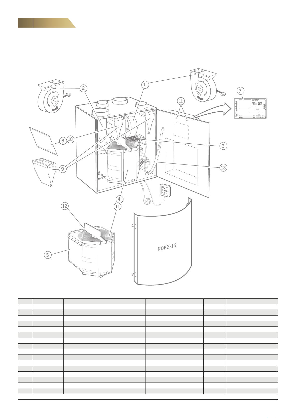
REPLACEMENT PARTS
RIGHT VERSION (RDKS-1)
LEFT VERSION (RDKS-2) NOT SHOWN.
Heat recovery unit RDKS - Technical manual
If the supply cord is damaged, it must be replaced by the manufacturer, an authorised service firm or a similarly qualified professional in order to avoid hazard.
Pos. Designation Name Included in Quantity Comment
1 RDKR-99-01-1 Supply air fan, unit with right-hand configuration RDKS-1 1
1 RDKR-99-01-2 Supply air fan, unit with left-hand configuration RDKS-2 1
2 RDKR-99-02-1 Extract air fan, unit with right-hand configuration RDKS-1 1
2 RDKR-99-02-2 Extract air fan, unit with left-hand configuration RDKS-2 1
3 RDKR-99-03 Electric heater (preheater, postheater) RDKS-1…/RDKS-2… 1
4 RDKS-99-02 Rotor, complete RDKS-1…/RDKS-2… 1
5 RDKR-99-08 Drive belt, rotor RDKS-1…/RDKS-2… 5
6 RDKS-99-01 Rotor motor RDKS-1…/RDKS-2… 1
7 RDKS-99-03 Control card RDKS-1…/RDKS-2-a-b-c-d-1 1
8 RDKG-99-14 Flat filter (G3) ISO Coarse (1 x) RDKS-1…/RDKS-2… 1
9 RDKG-99-15 Bag filter (M5) ISO Coarse 85% (1 x) RDKS-1…/RDKS-2… 1
9 RDKG-99-16 Bag filter (F7) ISO ePM1 50% (1 x) RDKS-1…/RDKS-2… 1
10 RDKG-99-22 Filter kit (G3) ISO Coarse, without frame RDKS-1…/RDKS-2… 10
11 RDKS-99-04 Temperature sensor RDKS-1.../RDKS-2... 3
12 RDKR-99-14 Brush strip RDKS-1.../RDKS-2... 1
13 RDKS-99-05 Cabling complete RDKS-1.../RDKS-2... 1
FläktGroup DC_9295GB_20190326_R5
We reserve the right to make changes without prior notice
Page 35

Heat recovery unit RDKS - Technical manual
EC DECLARATION OF CONFORMITY
Declaration of Conformity
In accordance with:
EU Directive for Machinery, 2006/42/EC
EU EMC Directive, 2014/30/EU
EU Directive for Energy related Products ErP 2009/125/EC
EU RoHS Directive, 2011/65/EU
35
ENCLOSURE II A
Manufacturer FläktGroup Sweden AB
Product Type:
Authorized To prepare technical documentation:
Jönköping 2019-01-01
Fläktgatan 1
551 84 Jönköping
Herewith declares that:
Manufacturer:
Commercial name:
The machine is designed and manufactured in accordance with the following standards, in relevant parts.
EN ISO 12100 Safety of machinery – General principles for design- Risk assessment and risk reduction
EN 60204-1 Safety of machinery; electrical equipment of machines; general requirements
EN 60335-1 Household and similar electrical appliances - Safety - Part 1: General requirements
EN 60335-2-40,31 Household and similar electrical appliances - Safety - Part 2: Particular requirements
EN 61000-6-1 Electromagnetic compatibility (EMC) - Part 6-1: Generic standards - Immunity for
EN 61000-6-3 Emission standard for residential, commercial and light-industrial environments.
EN 50106 Safety of household and similar electrical appliances - Particular rules for routine tests
EN 62233 Measurement methods for electromagnetic fields of household appliances and
EN 50581:2012 Technical documentation for the assessment of electrical and electronic products with
A risk analysis has been made according to requirements of the Directive for Machinery.
Ann-Sofie Andersson
Design- R&D
FläktGroup Sweden A B
Fläktgatan 1
551 84 Jönköping
The declaration applies only to the installation made according to FläkGroups instructions and assuming no
changes made to the unit.
Ventilation unit
FläktGroup Sweden AB
MiniMASTER, RDKS
HouseMASTER, RDAS
VillaMASTER, RDAF
residential, commercial and light-industrial environments
referring to appliances under the scope of EN 60335-1
apparatus with regard to human exposure
respect to the restriction of hazardous sustances
similar
Björn Norling, Quality Manager, FläktGroup Sweden AB, Jönköping
Postal Address Street Address Telephone Telefax Reg . no:
FläktGroup Sweden AB Fläktgatan 1 Nat 036 - 19 30 00 Nat 036 - 19 31 40 556239-2463
S-551 84 Jönköping Int +46 36 19 30 00 Int +46 36 19 31 40 Reg. office:
Sweden Jönköping
9850GB_RDKS_RDKG_RDAS_RDAF Declaration of conformity(2A) 201901
FläktGroup DC_9295GB_20190326_R5
FläktGroup Sweden AB
We reserve the right to make changes without prior notice
Page 36

36
DISPOSAL OF PRODUCTS AND PACKAGING MATERIALS
Separate at source according to local regulations.
Depending on the product, the following should be
removed when disposing of it:
- Circuit boards, cables, coils, motors, sensors etc.
- Filters other than metal ones (cooker hoods).
- Packaging material such as corrugated card
board, plastic and expanded polystyrene.
- Everything else should be disposed of as metal.
However, it should be noted that the unit also contains a vapour bar
rier, and sometimes mineral wool enclosed between the internal and
external walls, which should be removed.
- Light bulbs and fluorescent tubes
See www.flaktgroup.com for recycling instructions.
-
-
Heat recovery unit RDKS - Technical manual
FläktGroup DC_9295GB_20190326_R5
We reserve the right to make changes without prior notice
Page 37
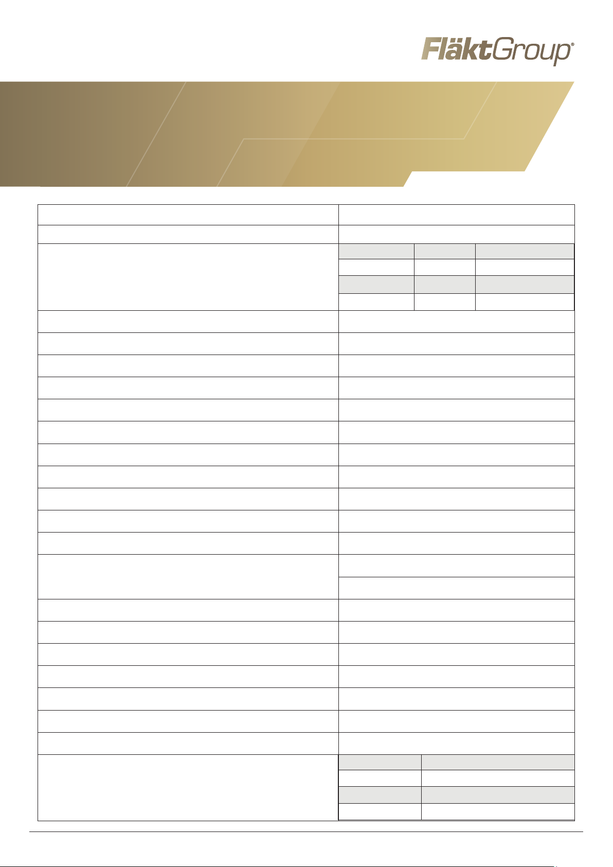
MiniMASTER RDKS + ISYteq Basic
PRODUCT INFORMATION IN ACCORDANCE WITH COMMISSION REGULATION
(EU) NO. 1254/2014 ANNEX IV AS REFERRED TO IN ARTICLE 3(1b)
(a) Brand FläktGroup
(b) Model designation MiniMASTER RDKS
Climate zone SEC Energy class
Cold -71.4 A+
(c) Specific energy use (SEC)
(d) Unit type Bidirectional
(e) Drive unit Stepless speed controller
(f) Heat recovery system Regenerative rotary energy recovery
(g) Thermal efficiency 80.5%
(H) Maximum airflow 209 m
Average -30.5 B
Warm -7.0 F
3
/h
(i) Additional fan output, maximum flow 128 W
(j) Sound power level 37 dB(A)
3
(k) Reference flow 0.041 m
/s
(l) Reference pressure difference 50 Pa
3
(m) Specified additional output 0.39 W/m
/h
(n) Control type Manual operation
2.9% (external
(o) Air leakage
3.5% (internal)
(p) Mixing rate Not applicable
(q) Visual filter alarm Filter alarm ISYteq Basic
(r) Instructions exhaust air grille Not applicable
(s) Web address for dismantling and installation http://flaktgroup.com
(t) Airflow sensitivity Not applicable
(u) Air tightness, unit not connected to duct Not applicable
(v) Annual electricity consumption 492 kWh/year
Climate zone Savings (kWh/year)
Cold 8371
(w) Annual heating saved
FläktGroup DC-9842SE 20180122_R0
Average 4279
Warm 1935
Page 38
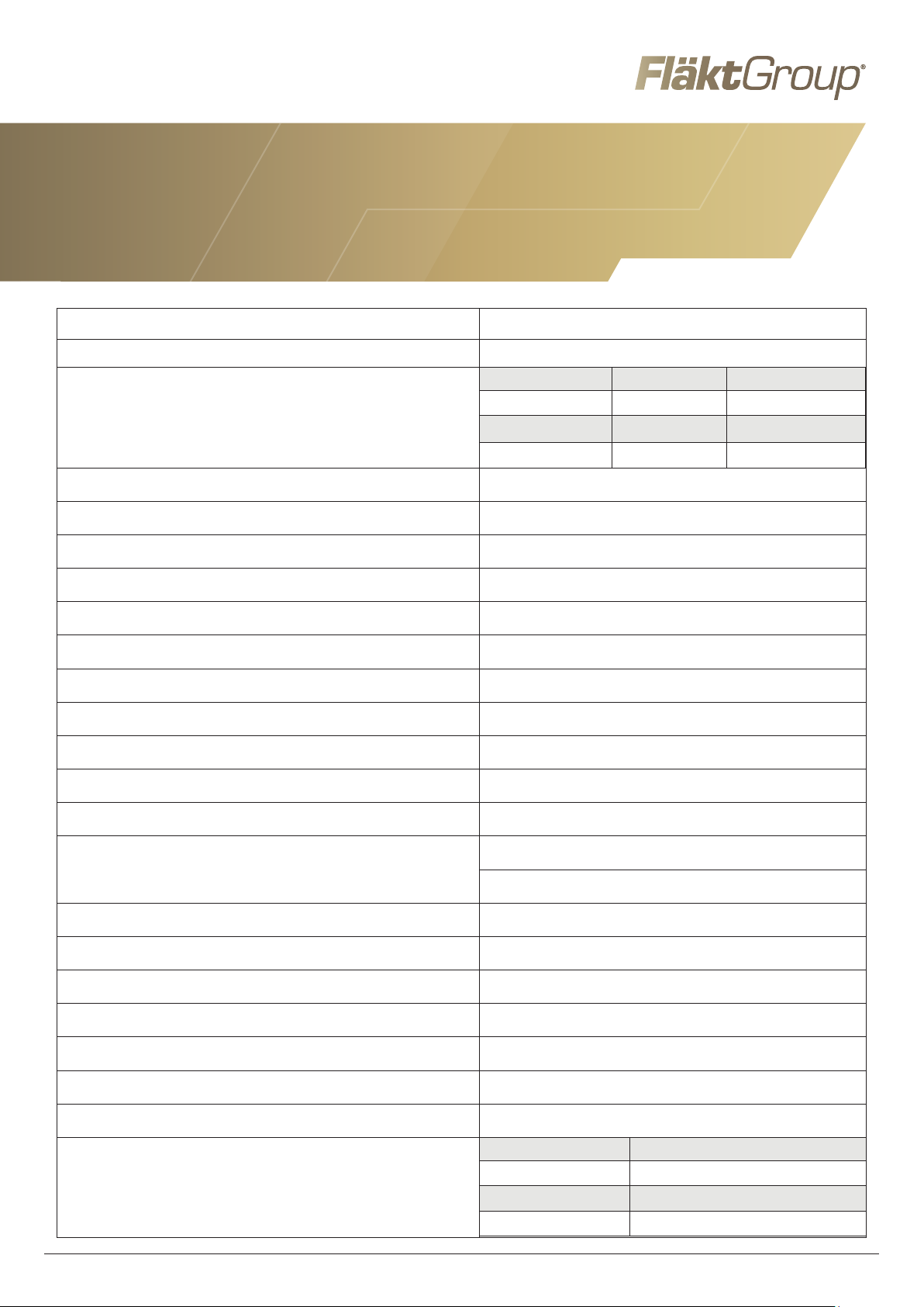
MiniMASTER RDKS + ISYteq Touch 3.5
PRODUCT INFORMATION IN ACCORDANCE WITH COMMISSION REGULATION
(EU) NO. 1254/2014 ANNEX IV AS REFERRED TO IN ARTICLE 3(1b)
(a) Brand FläktGroup
(b) Model designation MiniMASTER RDKS
Climate zone SEC Energy class
Cold -73.2 A+
(c) Specific energy use (SEC)
(d) Unit type Bidirectional
(e) Drive unit Stepless speed controller, stepless adjustment
(f) Heat recovery system Regenerative rotary energy recovery
(g) Thermal efficiency 80.5%
(H) Maximum airflow 209 m
Average -32.0 B
Warm -8.4 F
3
/h
(i) Additional fan output, maximum flow 128 W
(j) Sound power level 37 dB(A)
3
(k) Reference flow 0.041 m
/s
(l) Reference pressure difference 50 Pa
3
(m) Specified additional output 0.39 W/m
/h
(n) Control type Time control
2.9% (external
(o) Air leakage
3.5% (internal)
(p) Mixing rate Not applicable
(q) Visual filter alarm Filter alarm ISYteq Touch 3.5
(r) Instructions exhaust air grille Not applicable
(s) Web address for dismantling and installation http://flaktgroup.com
(t) Airflow sensitivity Not applicable
(u) Air tightness, unit not connected to duct Not applicable
(v) Annual electricity consumption 440 kWh/year
Climate zone Savings (kWh/year)
Cold 8432
(w) Annual heating saved
FläktGroup DC-9845SE 20180122_R2
Average 4310
Warm 1949
Page 39
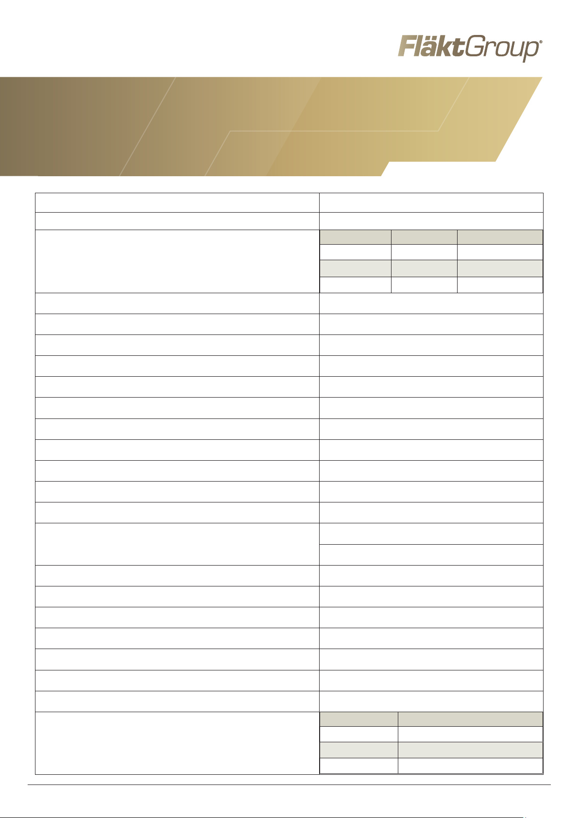
MiniMASTER RDKS + ISYteq Touch 3.5pp + CO
2
PRODUCT INFORMATION IN ACCORDANCE WITH COMMISSION REGULATION
(EU) NO. 1254/2014 ANNEX IV AS REFERRED TO IN ARTICLE 3(1b)
(a) Brand FläktGroup
(b) Model designation MiniMASTER RDKS
Climate zone SEC Energy class
Cold -76.7 A+
(c) Specific energy use (SEC)
Average -34.8 A
Warm -10.9 E
(d) Unit type Bidirectional
(e) Drive unit Stepless speed controller
(f) Heat recovery system Regenerative rotary energy recovery
(g) Thermal efficiency 80.5%
3
(H) Maximum airflow 209 m
/h
(i) Additional fan output, maximum flow 128 W
(j) Sound power level 37 dB(A)
3
(k) Reference flow 0.041 m
/s
(l) Reference pressure difference 50 Pa
3
(m) Specified additional output 0.39 W/m
/h
(n) Control type Central on-demand control
2.9% (external
(o) Air leakage
3.5% (internal)
(p) Mixing rate Not applicable
(q) Visual filter alarm Filter alarm ISYteq Touch 3.5
(r) Instructions exhaust air grille Not applicable
(s) Web address for dismantling and installation http://flaktgroup.com
(t) Airflow sensitivity Not applicable
(u) Air tightness, unit not connected to duct Not applicable
(v) Annual electricity consumption 356 kWh/year
Climate zone Savings (kWh/year)
Cold 8554
(w) Annual heating saved
FläktGroup DC-9846SE 20180122_R2
Average 4372
Warm 1977
Page 40

WWW.FLAKTGROUP.COM MINIMASTER RDKS
FläktGroup is the European market leader in smart, energy-efficient ventilation
systems for optimal indoor comfort, critical applications and fire safety. Our
products and solutions are based on innovative technology, high quality and
superior performance, backed by over 100 years of experience in the industry.
With the market’s widest range of products and strong market presence in
65 countries worldwide, we are always close to you – with a clear focus
on delivering Excellence in Solutions.
FG_DC_9295GB_Minimaster RDKS_IN-MA-CM-SP_20190326_R5 © Copyright 2019 FläktGroup J8013826-2301
FLÄKTGROUP PRODUCT AREAS
Air Treatment | Air Movement | Air Distribution | Chilled Beams
& Chilled Beam Cassettes | Air FiltrationAir Management & ATDs
| Air Conditioning & Heating | Control | Service
» Learn more on www.flaktgroup.com
or contact one of our offices
 Loading...