

FläktGroup CPD Series, CPDD, CPDL, CPDF Operation, Maintenance, Installation, Commissioning, Spare Parts
Page 1
COOKER HOOD
CPD
OPERATION, MAINTENANCE, INSTALLATION, COMMISSIONING, SPARE PARTS
Page 2

2
2
Cooker hood CPDD, CPDL - Installation and Maintenance Manual
CONTENTS
OPERATION AND MAINTENANCE (FOR USER)
Cleaning of cooker hood ......................................................................... 3
Cleaning of grease filters ......................................................................... 3
Replacement of low energy lamp ........................................................ 3
General information .................................................................................... 3
Operation .........................................................................................................4
CPDL - Setting of supply air temperature ......................................... 5
INSTALLATION (FOR INSTALLER AND SERVICE PERSONNEL)
CPDD for heat recovery unit ACF ..........................................................7
CPDD for BAF extract air fan ................................................................ 9
CPCZ-07 Installation of nipples (ACF before 1988) ................... 10
CPDL for heat recovery units RDKB and RDKE ............................ 11
ADJUSTMENT, COMMISSIONING (FOR INSTALLER AND SERVICE PERSONNEL)
Basic ventilation ........................................................................................17
Forced ventilation .....................................................................................18
MISCELLANEOUS
Spare parts CPDD, CPDF, CPDL ..................................................................19
Declaration of conformity ...............................................................................20
Disposal of products and packaging materials .....................................21
WARNING! THE APPLIANCE MAY BE USED BY CHILDREN OVER THE AGE OF 8, PERSONS (INCLUDING
CHILDREN) WITH PHYSICAL, SENSORY OR MENTAL DISABILITIES OR LACK OF KNOWLEDGE OR
EXPERIENCE, PROVIDED THEY HAVE RECEIVED INSTRUCTION OR INFORMATION ON SAFE USE OF THE
APPLIANCE AND UNDERSTAND THE POTENTIAL RISKS. CHILDREN MAY NOT PLAY WITH THE APPLIANCE.
CHILDREN MAY NOT CLEAN OR PERFORM MAINTENANCE ON THE APPLIANCE WITHOUT SUPERVISION.
FläktGroup DC_8759GB_20190207_R1 We reserve the right to make changes without prior notice
Page 3
Cooker hood CPDD, CPDL - Installation and Maintenance Manual
1
2
33
OPERATION AND MAINTENANCE
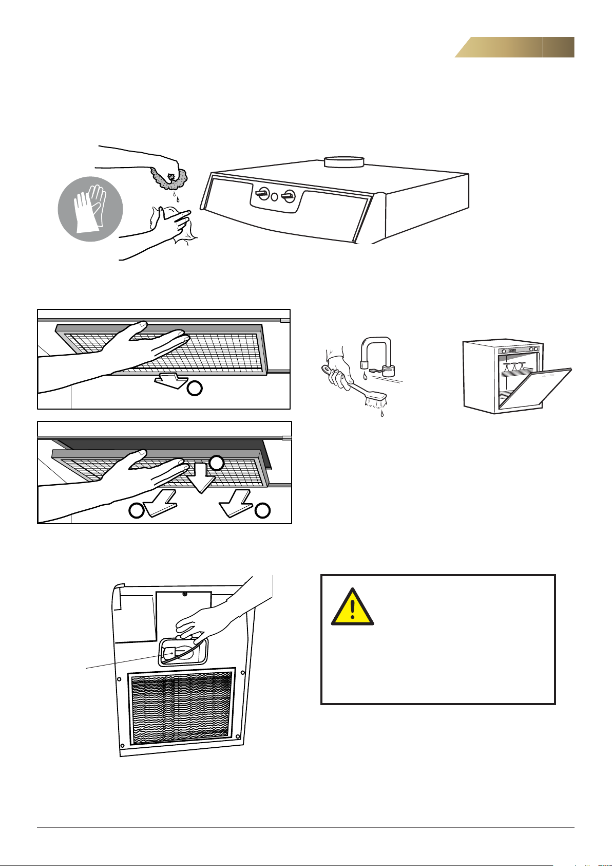
CLEANING THE COOKER HOOD
Do not use abrasive sponge or cloth.
3
CLEANING OF GREASE FILTERS
REPLACEMENT OF LOW ENERGY LAMP
NOTE! Do not use the cooker hood
without the grease filters fitted.
alt.
Check the grease filters every week.
Clean if needed, either by hand or in a dishwasher.
GENERAL
There is a fire risk if grease filters are not
cleaned according to the instructions.
The cooker hood may become hot during cook
ing.
Do not flambé under the cooker hood.
11 W/E14
FläktGroup DC_8759GB_20190207_R1 We reserve the right to make changes without prior notice
If the supply cord is damaged, it must be replaced by the
manufacturer, the distributor or a similarly qualified professional in order to avoid hazard.
-
Page 4
4
4
OPERATION AND MAINTENANCE
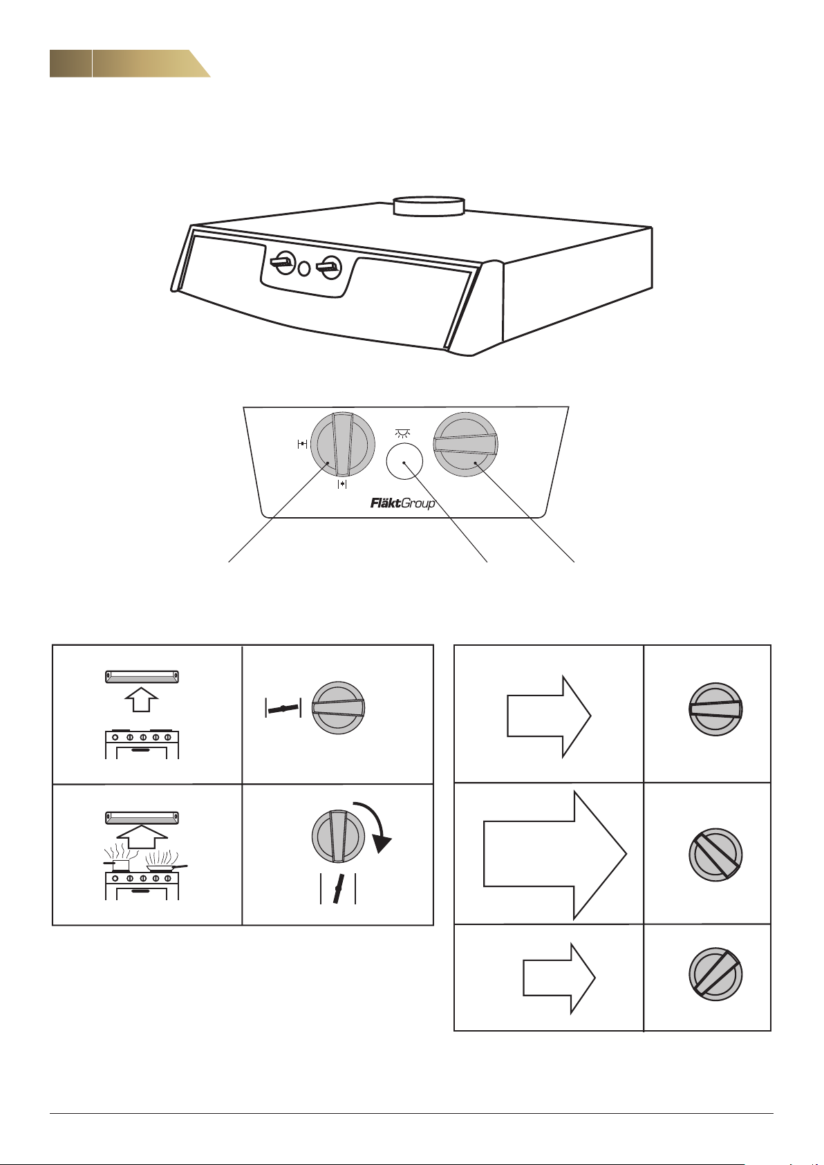
OPERATING OF CPDD, CPDL
Cooker hood CPDD, CPDL - Installation and Maintenance Manual
2
1
MIN
Booster knob Lighting Fan speed adjustment knob
2
NORMAL
1
MIN
2
MAX
1
MIN
2
MIN
1
MIN
FläktGroup DC_8759GB_20190207_R1 We reserve the right to make changes without prior notice
Page 5
Cooker hood CPDD, CPDL - Installation and Maintenance Manual
OPERATION AND MAINTENANCE
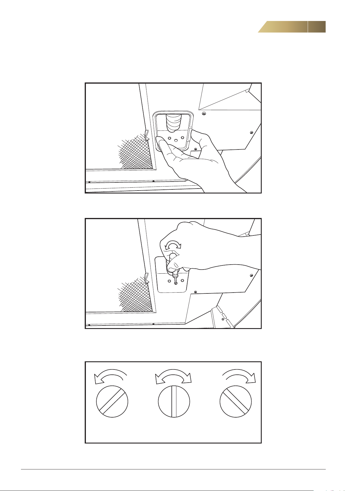
CPDL - SETTING OF SUPPLY AIR TEMPERATURE (POSTHEATER)
5
1. Remove the lamp glass.
2. Use a screwdriver to set the supply air temperature downstream of the
ventilation unit. The factory setting is 10 °C.
Factory setting
Min - Off 10° C 20° C
3. The supply air temperature downstream of the unit can be adjusted steplessly
between the lowest setting and 20 °C.
FläktGroup DC_8759GB_20190207_R1 We reserve the right to make changes without prior notice
Page 6
6
6
OPERATION AND MAINTENANCE
CPDL - SETTING OF SUPPLY AIR TEMPERATURE (POSTHEATER)
Cooker hood CPDD, CPDL - Installation and Maintenance Manual
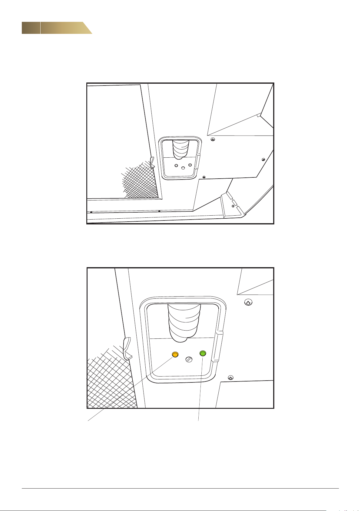
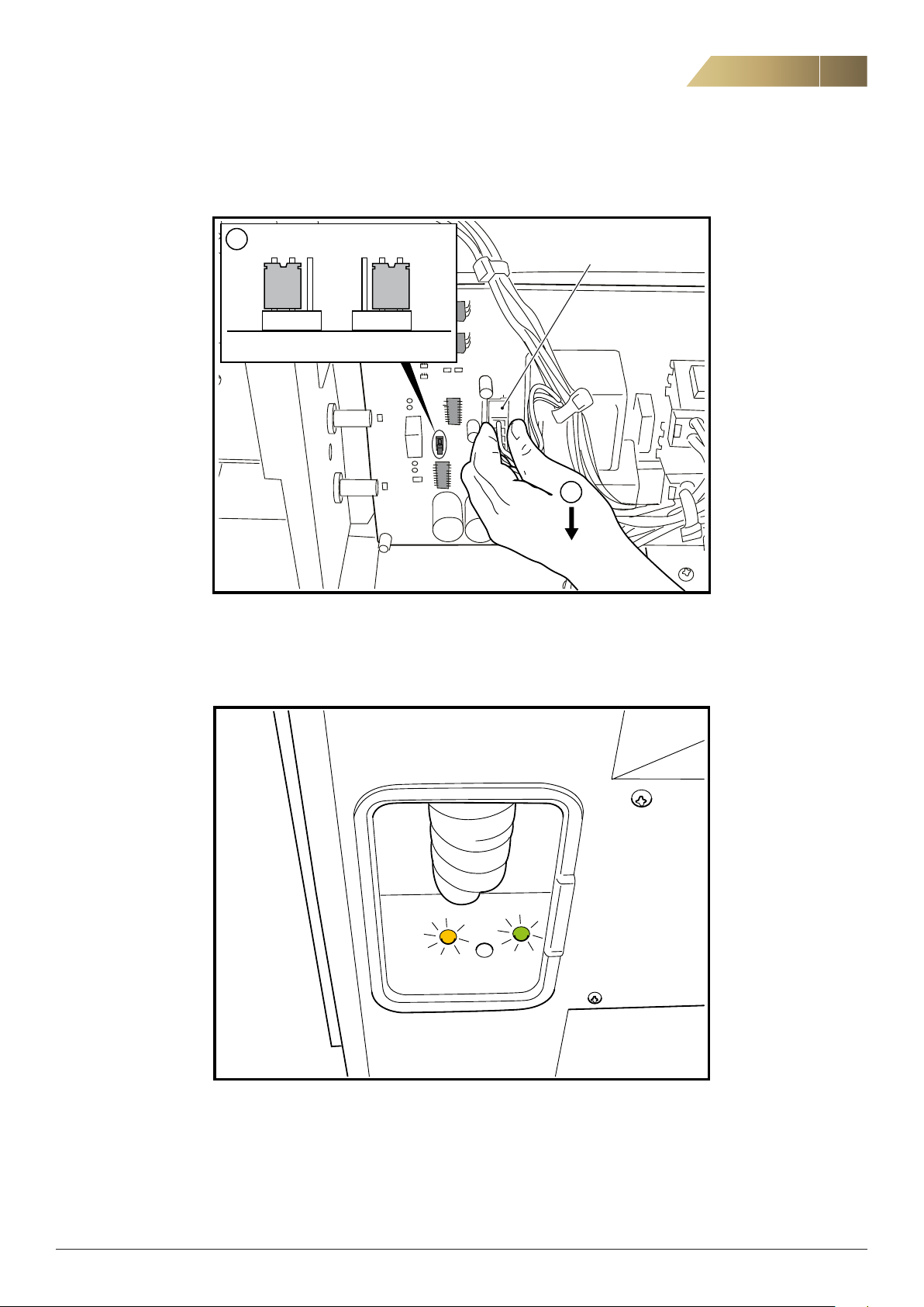
4. The indicator lights for the electric post-heater and defrosting functions are located in the cooker hood as shown in the figure above.
If the yellow light is illuminated, the
electric post-heater is in operation.
FläktGroup DC_8759GB_20190207_R1 We reserve the right to make changes without prior notice
If the green light is illuminated, de
frosting is in progress.
-
Page 7
Cooker hood CPDD, CPDL - Installation and Maintenance Manual
INSTALLATION (FOR INSTALLER AND SERVICE PERSONNEL)
CPDD FOR HEAT RECOVERY UNIT ACF
All cooker hoods must be connected directly or indirectly via the heat recovery unit/extract air fan to earth.
7
PROCEDURE
1. Disconnect the unit from the power supply by pulling out the
plug.
If the hood is permanently attached, the work must be performed by a qualified installation engineer.
2. Note the switch position for Normal operating speed.
The switch is on the top of the cooker hood. There are six settings on the switch. The switch is accessed by opening the
door to the ventilation unit.
3. Disconnect the drainage hose from the cooker hood.
4. Remove the BHG hood. The hood is attached with four screws
which are accessed by opening the door to the unit.
5. Connection to drainage hose.
Alt. 2
a) Make a vertical slit in the wall measuring 70 mm. Pull the drain-
age hose upwards until it protrudes roughly 40 mm below the
lower edge of the unit. Adjust the nipple on the drainage cup so
that it points sideways towards the hose. Remove the grease
filter and the cover plate on the new hood and, if necessary,
reposition the cable on the transformer until it is tensioned in
the same way as on the old transformer. By default, the cable is
connected to pin 5, which is 150 V. It is easiest to set the volt
age before installing the hood.
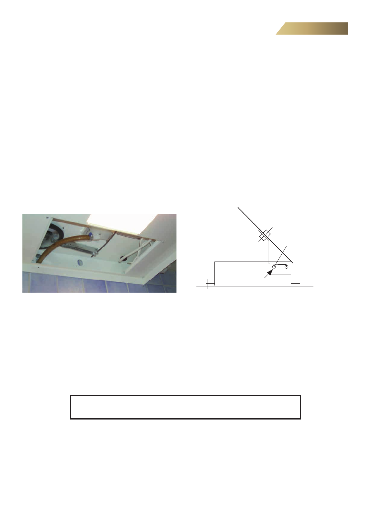
6. Before installation, prepare the fire damper by fixing it with the
included melting rivet (125 °C). Flatten the end of the rivet using
pliers.
-
Melting rivet
Alt. 1
a) Make a slit in the wall large enough for the drainage hose to fit
through. The slit should reach from approximately 10 mm below
the centre on the bottom of the unit down to the drainage hose.
B) Position the drainage hose so that it protrudes out of the wall
25 mm below the lower edge of the unit. If a new hose needs to
be installed, it must be armoured to prevent creasing. Position
the hose so that if forms a water trap. Use the old hose’s posi
tion for reference.
NOTE! INSTALLATION, COMMISSIONING AND ADJUSTMENT AS DESCRIBED IN THESE
INSTRUCTIONS MUST BE CARRIED OUT BY QUALIFIED AND AUTHORISED PERSONNEL.
7. Install the cooker hood under the ventilation unit, using the
screws and mounting plate from the old cooker hood. Make
sure the hood creates a tight seal against the unit. Replace the
sealing strip under the unit if necessary.
-
FläktGroup DC_8759GB_20190207_R1 We reserve the right to make changes without prior notice
Page 8
8
D
Bakkant kåpa
8
Cooker hood CPDD, CPDL - Installation and Maintenance Manual
INSTALLATION (FOR INSTALLER AND SERVICE PERSONNEL)
CPDD FOR HEAT RECOVERY UNIT ACF, CONT’D.
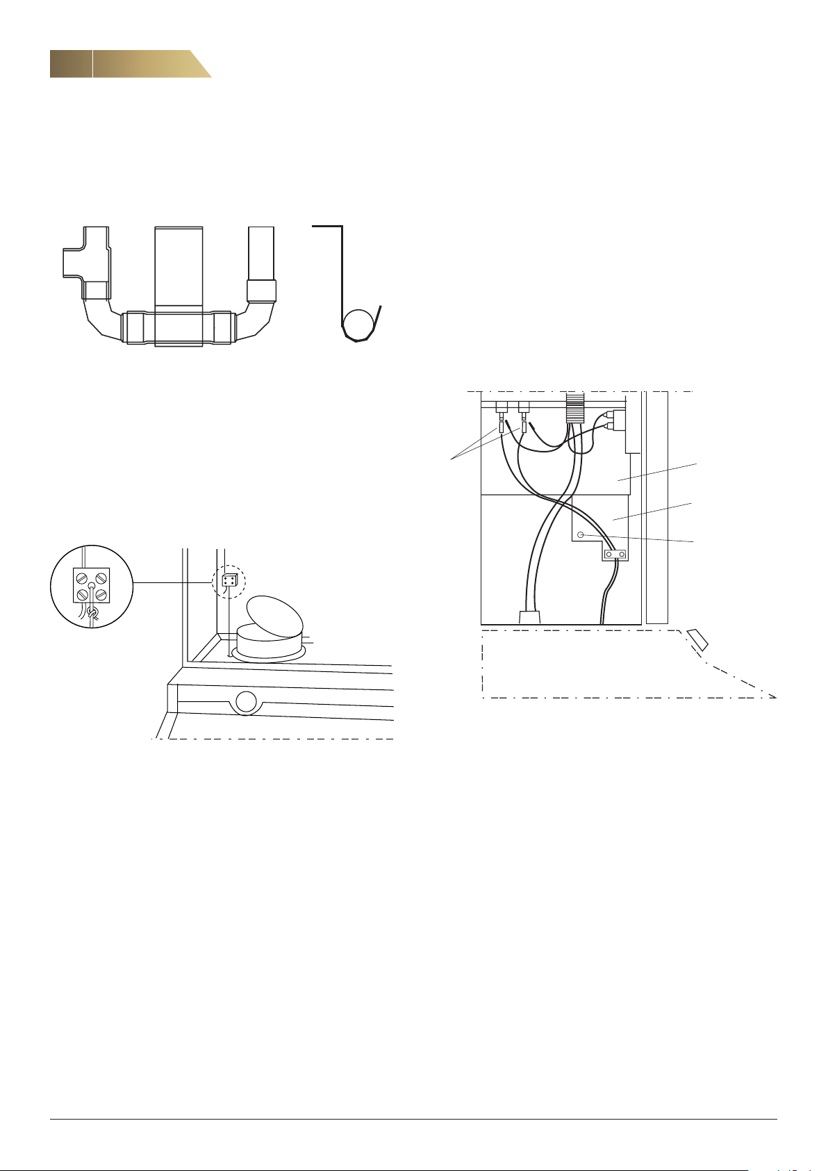
8. Assemble the water trap as shown in the figure.
9. Connect the drainage hose to the water trap. Make sure that
the damper is not obstructed by the drainage hose when it is in
the open position, and that a water trap cannot form inside the
hood.
10. Connect the damper valve in the cooker hood with the throttle
damper in the ventilation unit. To do this, thread the nylon line
through the terminal block and tighten the screws while the
valve in the cooker hood is closed and the damper in the venti
lation unit is open.
NOTE! The CPDD cooker hood does not have a power output indicator
light. If a CPDD hood is to be used to replace a BHG.614100, the fol
lowing steps must be carried out by a qualified electrician:
1. Remove the cover plate E in the ventilation unit and disconnect
the cables from the element connections D.
2. Remove the cables for the indicator light from the disconnected
cables (double AMP).
3. Reconnect the AMP cables to the element connections.
4. Remove the strain relief connector A in screw B.
5. Connect cover plate E and fix it securely into place.
-
E
-
A
B
11.
Connect the 12-pole connector to the corresponding connection
point in the unit.
12. Reinstall the filter. Plug the plug for the cooker hood into the
earthed wall socket.
13. Check whether the air flow settings (Settings 1 and 2) feel right.
The adjustment damper in the hood is delivered with a factory
setting that is suitable for most installations.
14. Cover any untreated surfaces underneath the cooker hood with,
for instance, a teak strip.
FläktGroup DC_8759GB_20190207_R1 We reserve the right to make changes without prior notice
Page 9
Cooker hood CPDD, CPDL - Installation and Maintenance Manual
162
INSTALLATION (FOR INSTALLER AND SERVICE PERSONNEL)
CPDD FOR BAF TYPE EXTRACT AIR FAN
PROCEDURE
1. Disconnect the unit from the power supply by pulling out the
plug. If the hood is permanently attached, the work must be
performed by a qualified installation engineer.
2. Note the switch position for Normal operating speed. The
switch is on the top of the cooker hood. There are six settings
on the switch.
The switch can be accessed by removing the spice rack.
3. Pull apart the connector connecting the cooker hood with the
fan.
4. Dismantle the BAF extract air fan.
5. Remove the BHG hood. The hood is fixed with four screws.
8. Before installation, prepare the fire damper by fixing it with the
included melting rivet (125 °C). Flatten the end of the rivet using
pliers.
9. Install the new cooker hood.
10. Connect the damper valve in the cooker hood with the throt
tle damper in the fan. To do this, thread the nylon line through
the terminal block and tighten the screw while the valve in the
cooker hood is closed and the damper in the fan is open.
9
-
50
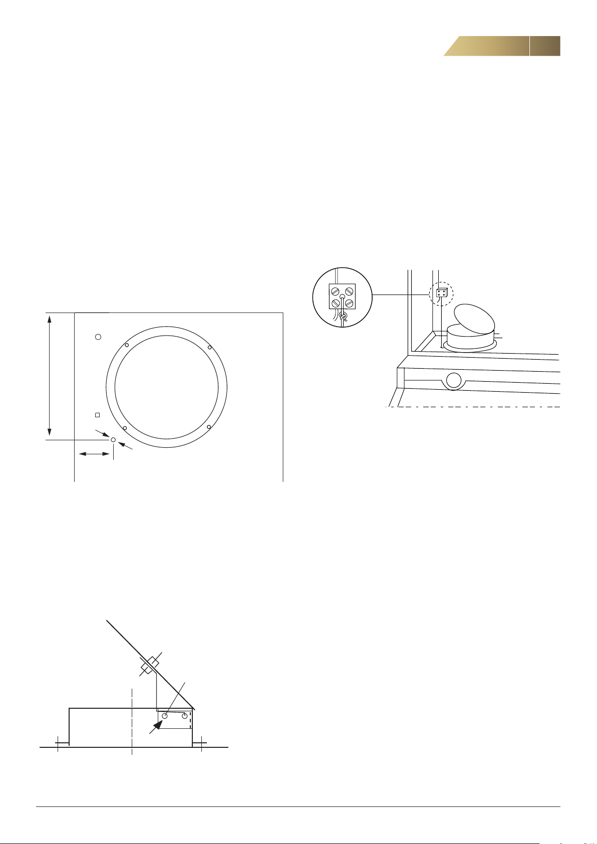
6. Drill a hole Ø = 5.0 mm according to the figure below in the
new CPDD hood.
7. Move the cord with the plastic lead-in to the new hole.
Remove the grease filter and the cover plate on the new hood
and, if necessary, reposition the cable on the transformer until
it is tensioned in the same way as on the old transformer. The
product is delivered from the factory with the cable connected
to pin 5, which is 150 V. It is easiest to set the voltage before
installing the hood.
ø5
Melting rivet
11. Connect the 12-pole connector to the corresponding connection
point in the fan.
12. Reinstall the filter. Plug the plug for the cooker hood into the
earthed wall socket.
13. Check whether the air flow settings (Settings 1 and 2) feel right.
The adjustment damper in the hood is delivered with a factory
setting that is suitable for most installations.
14. Cover any untreated surfaces underneath the cooker hood with,
for instance, a teak strip.
Fire safety valve on cooker hood CPDD
FläktGroup DC_8759GB_20190207_R1 We reserve the right to make changes without prior notice
Page 10
10
Bakkant kåpa
10
Cooker hood CPDD, CPDL - Installation and Maintenance Manual
INSTALLATION (FOR INSTALLER AND SERVICE PERSONNEL)
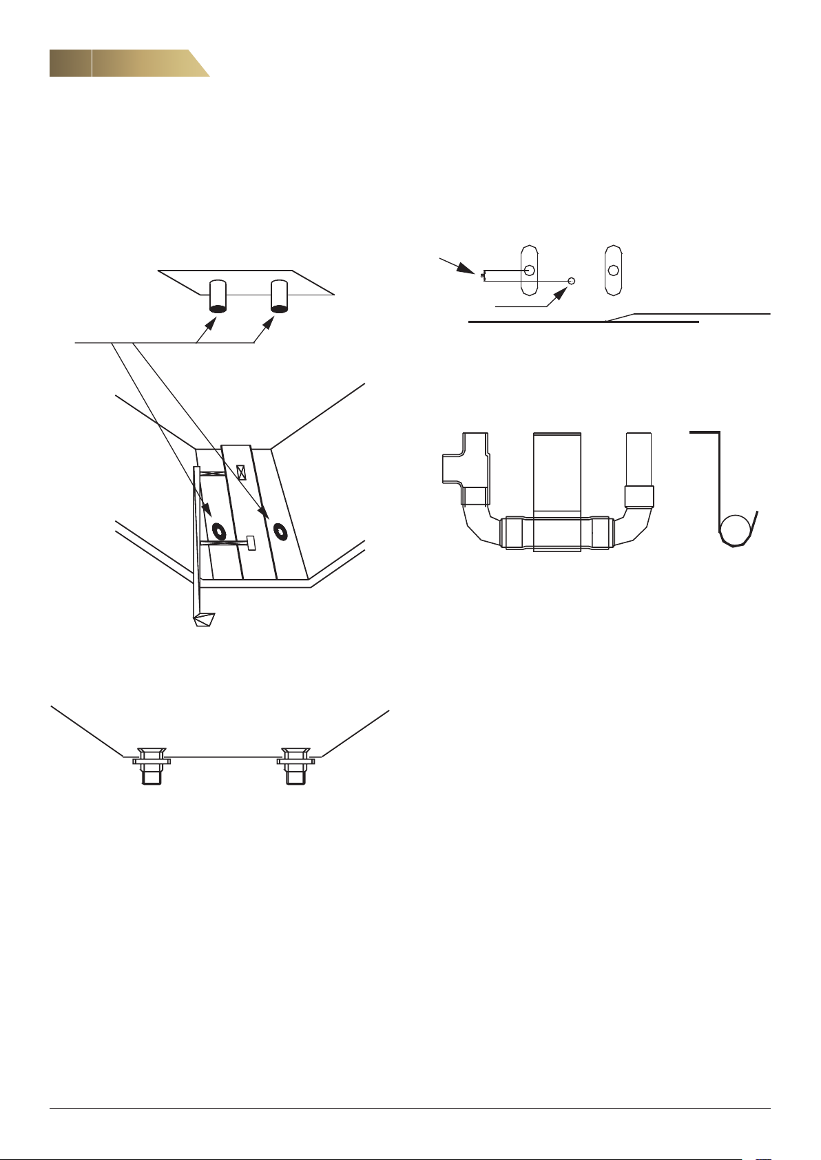
CPCZ-07 INSTALLATION OF NIPPLES (ACF BEFORE 1988)
PROCEDURE
1. Remove the old cooker hood.
2. Remove the two old nipples from inside the unit using a drill.
4. Drill a hole with a diameter of 3.2 mm in the hood roughly 10 mm
behind the centre of the nipples.
10 mm
3,2 mm
5. Install the mounting plate supplied.
6. Install the new water trap and bend the mounting plates around the
hose (see figure below). Apply a silicone sealant between the nip
ples and the water trap.
Rear end casing
-
3. Install the new nipples. Apply a silicone sealant around the top of
the nipples.
FläktGroup DC_8759GB_20190207_R1 We reserve the right to make changes without prior notice
Page 11
Cooker hood CPDD, CPDL - Installation and Maintenance Manual
INSTALLATION (FOR INSTALLER AND SERVICE PERSONNEL)
CPDL
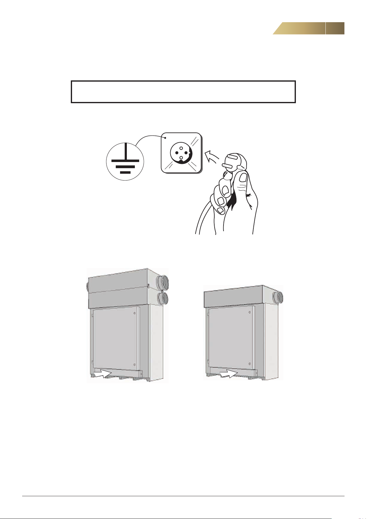
NOTE! INSTALLATION, COMMISSIONING AND ADJUSTMENT AS DESCRIBED IN THESE
INSTRUCTIONS MUST BE CARRIED OUT BY QUALIFIED AND AUTHORISED PERSONNEL.
Read the installation instructions in their entirety before starting work.
11
1. Disconnect the mains cable for the old cooker hood.
RDKERDKB
2. Disconnect the safety plate under the door of the unit.
3. Disconnect the cable with the 9-pole connector in the unit
4. Remove the grease filter in the old cooker hood.
5. Unscrew the screws on the old cooker hood and remove it.
6. Check the fan speed setting on the transformer in the old cooker hood (setting 1–6).
FläktGroup DC_8759GB_20190207_R1 We reserve the right to make changes without prior notice
Page 12
12
12
Cooker hood CPDD, CPDL - Installation and Maintenance Manual
INSTALLATION (FOR INSTALLER AND SERVICE PERSONNEL)
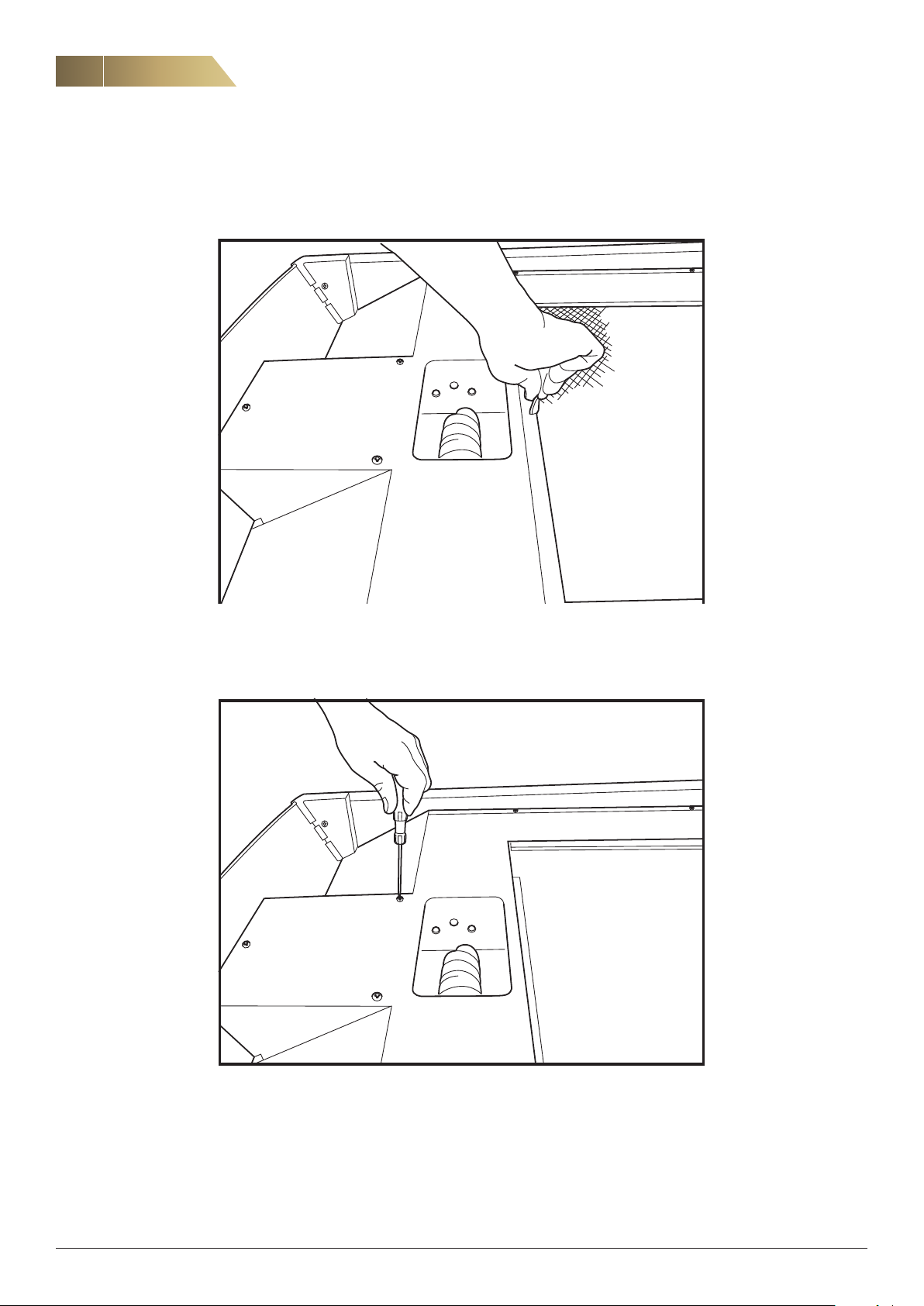
CPDL - FAN SPEED SETTING (AIRFLOW)
NOTE! This must be done before installing the new CPDL hood.
7. Remove the grease filter in the hood.
(x7)
8. Unscrew the screws (x7) securing the safety plate.
FläktGroup DC_8759GB_20190207_R1 We reserve the right to make changes without prior notice
Page 13
Cooker hood CPDD, CPDL - Installation and Maintenance Manual
INSTALLATION (FOR INSTALLER AND SERVICE PERSONNEL)
CPDL - FAN SPEED SETTING (AIRFLOW), CONT’D.
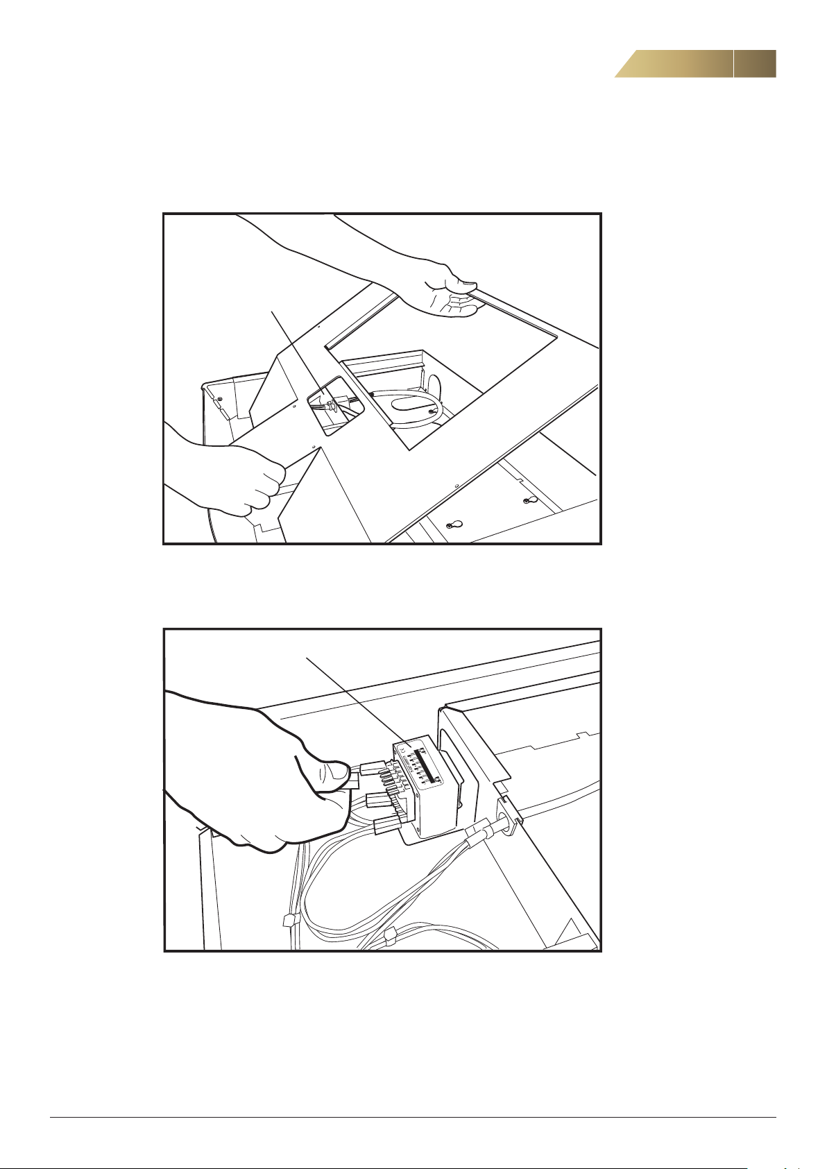
Transformer
13
9. Remove the safety plate in order to see and access the transformer.
Transformer
10. Move the connection in the upper row to the position that corresponds to
its position on the transformer in the old hood. Position 1 in the old hood
corresponds to position 2 in the CPDL and so forth, up to position 6 in the
old hood, which corresponds to position 7 in the CPDL.
Note that connection 1 should not be moved.
FläktGroup DC_8759GB_20190207_R1 We reserve the right to make changes without prior notice
Page 14
14
14
Cooker hood CPDD, CPDL - Installation and Maintenance Manual
INSTALLATION (FOR INSTALLER AND SERVICE PERSONNEL)
CPDL - FAN SPEED SETTING (AIRFLOW), CONT’D.
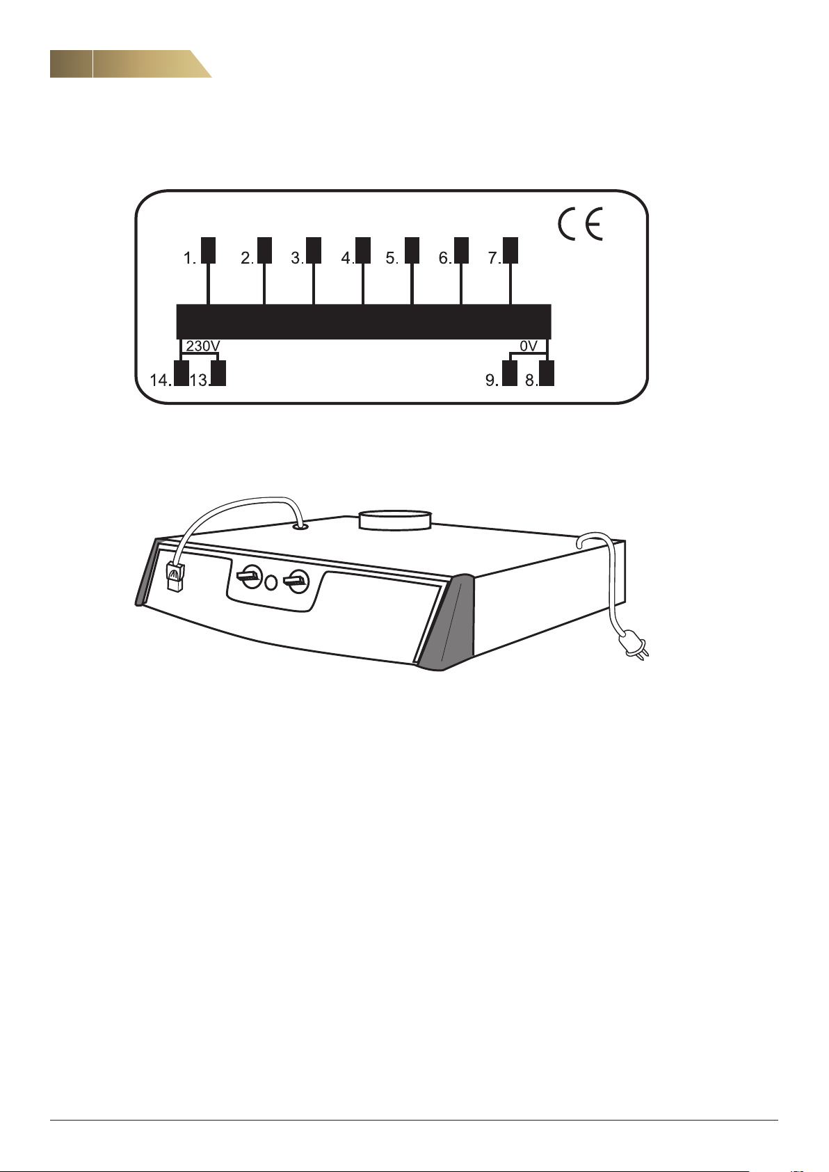
5-087-000073
100V
11. The figure above shows the markings on the transformer in the CPDL in detail. Position 2 (115 V)
to position 7 (190 V).
12. Place the cable with the 9-pole connector over the front of the cooker hood and place the mains
cable over the right side of the hood.
13. Glue the gasket provided round the cooker hood’s outlet to create a seal against the unit.
14. Install the CPDL hood under the unit in the same way as the old hood. Note that the hood should
be installed without fixing the safety plate into place.
15. Connect the cable with the 9-pole connector from the hood to the unit’s connector. Check that
the stop lugs have locked the connector into place.
16. Reconnect the safety plate under the door of the unit.
17. Connect the mains cable from the hood.
18. Check that the fan speed setting is correct by measuring the airflow.
If the fan speed setting needs changing, follow the instructions in points 10-11.
115V
125V
135V
150V
170V
190V
FläktGroup DC_8759GB_20190207_R1 We reserve the right to make changes without prior notice
Page 15
Cooker hood CPDD, CPDL - Installation and Maintenance Manual
INSTALLATION (FOR INSTALLER AND SERVICE PERSONNEL)
CPDL - TESTING OF POST-HEATING AND DEFROSTING FUNCTIONS
15
OPERATION TEST
2
Temperature
sensor contact
Jumpers
1
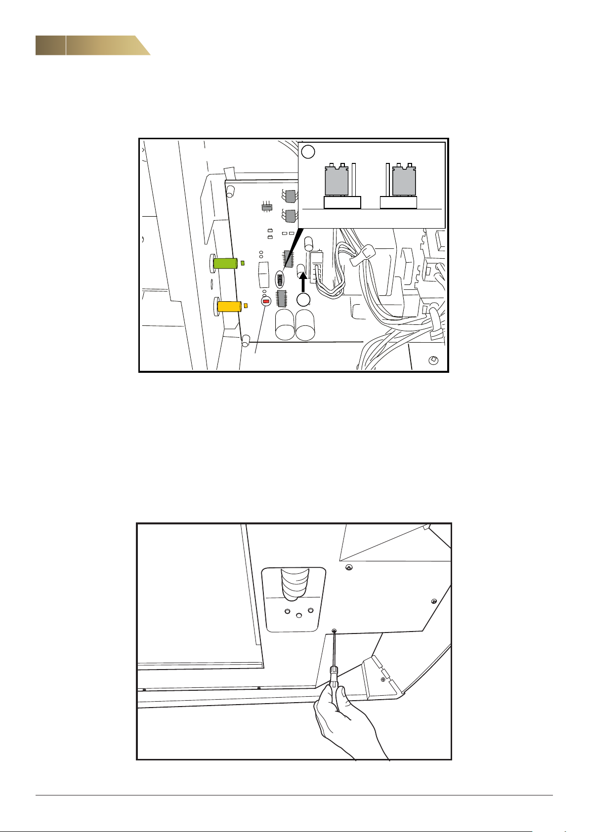
19. Cut the power supply to the cooker hood and disconnect the temperature sensor
connector on the control board. Move the jumper to the TEST position, then switch
on the power.
20. If the functions are correct, the yellow and green lights will flash alternately. Check
that both the electric air heaters have heated up, then cut the power supply again.
Measure the temperature sensors’ resistance in the sensor connector. It should be
approximately 10 kΩ at +20 °C.
Red-Green cable = Post-heater
White-Green cable = Pre-heater (Defrosting)
FläktGroup DC_8759GB_20190207_R1 We reserve the right to make changes without prior notice
Page 16
16
16
Cooker hood CPDD, CPDL - Installation and Maintenance Manual
INSTALLATION (FOR INSTALLER AND SERVICE PERSONNEL)
CPDL - TESTING OF POST-HEATING AND DEFROSTING FUNCTIONS, CONT’D.
OPERATION TEST
2
1
Jumpers
Running indication
21. Reconnect the temperature sensor connector to the control board, move the
jumper back to OPERATING mode and switch on the power.
Indicator lights on the control board:
Yellow = Post-heater in operation
Green = Pre-heater in operation (defrosting)
Red = Running indication
Steady illumination = Everything OK
Flashing = Defrosting cycle activated
Flashing alternately yellow and green = Test mode activated
22. Reconnect the safety plate.
FläktGroup DC_8759GB_20190207_R1 We reserve the right to make changes without prior notice
Page 17
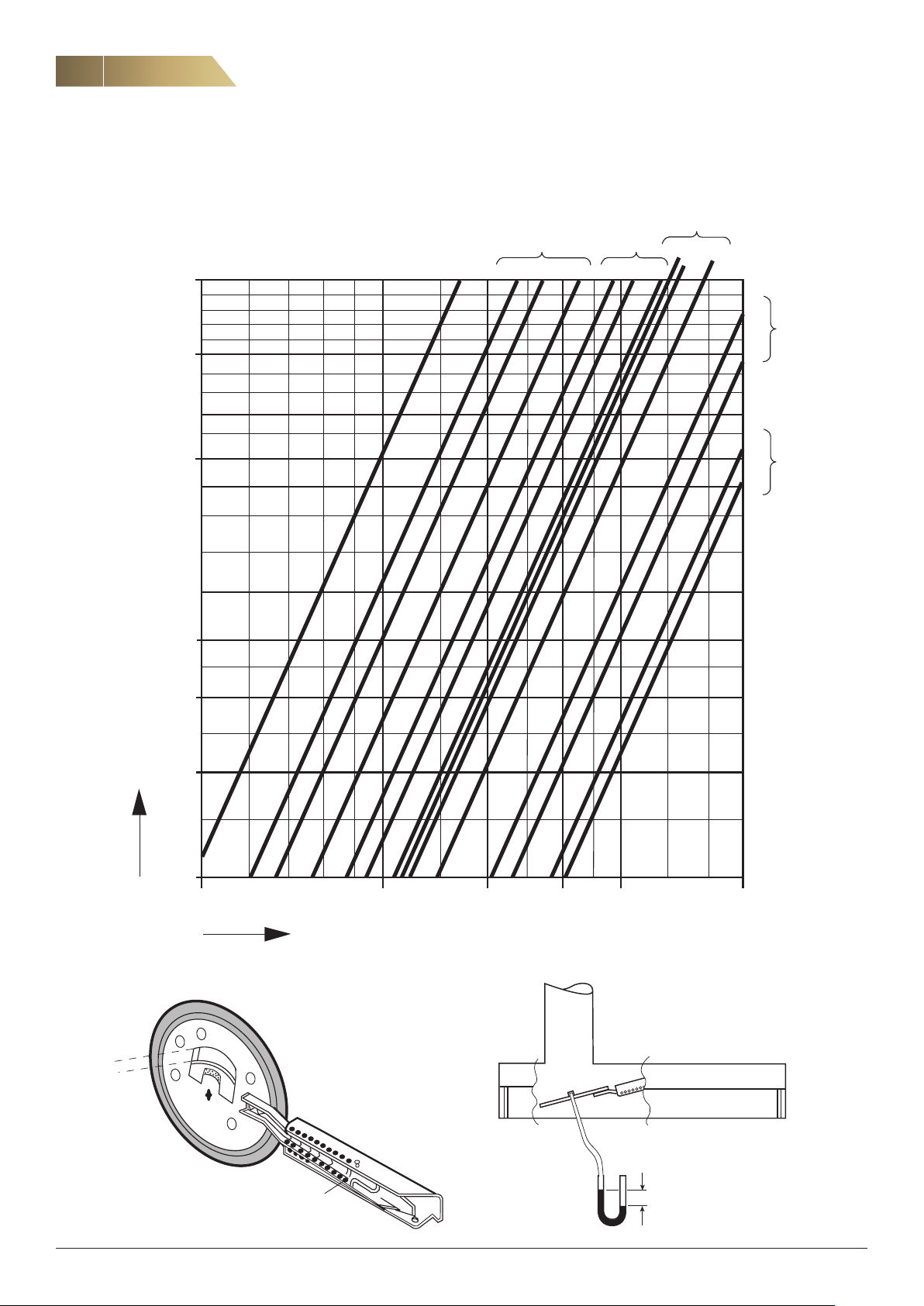
Cooker hood CPDD, CPDL - Installation and Maintenance Manual
c
a
q l/s
30 + 1xC
ADJUSTMENT (FOR INSTALLER AND SERVICE PERSONNEL)
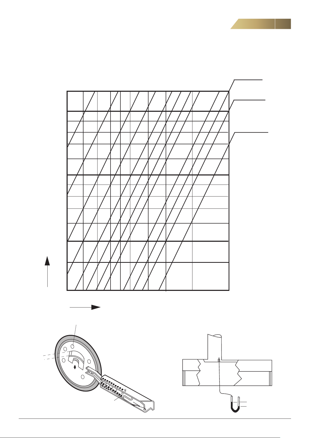
BASIC VENTILATION
17
Pa a =
250
200
100
7,5 10 12,5 15 20 25
30
30 + 2xC
30 + 4xC
50
m
Δp
40
30
5
6
7
8
10 12
9
15
20
30
b
FläktGroup DC_8759GB_20190207_R1 We reserve the right to make changes without prior notice
∆p
Page 18
18
a
18
Cooker hood CPDD, CPDL - Installation and Maintenance Manual
ADJUSTMENT (FOR INSTALLER AND SERVICE PERSONNEL)
FORCED VENTILATION
b = 5
a = 25 10
200
150
100
7 9
25 25
1015 15
10
11
15
25
a b
10
13
25
a
10
14
25
50
40
, Pa
m
∆p
30
20
10
20 30 40 50 80
q, l/s
b
FläktGroup DC_8759GB_20190207_R1 We reserve the right to make changes without prior notice
∆p
Page 19
Cooker hood CPDD, CPDL - Installation and Maintenance Manual
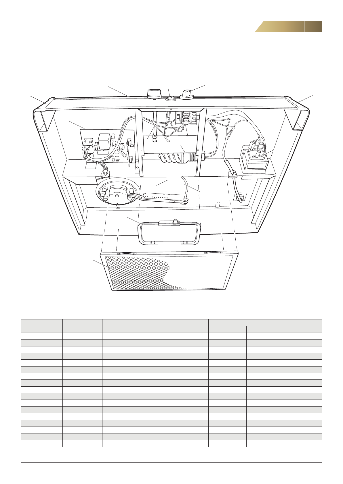
REPLACEMENT PARTS
COOKER HOOD CPDD, CPDF, CPDL
123
4 4
14
11
5
6
13
8
7
19
9
10
Always cut the power before starting any work on the equipment. All work must be carried out by qualified personnel to avoid hazard.
Pos. Quantity Designation Name
1 25 CPDA-99-01 Knob • • •
2 10 CPDA-99-02 Lighting switch • • •
3 1 CPDC-99-03 Front panel, 2-knobs, 600 mm • • •
3 1 CPDC-99-04 Front panel, 2 knobs, 700 mm •
4 10 + 10 CPDA-99-07 Black plastic corners, right and left • • •
5 1 CPDL-99-01 Timer with shaft • •
5 1 CPDD-99-02 Rotary switch centre with shaft •
6 10 CPCA-99-09 Lamp socket, E14 snap-in • • •
6 10 CPDA-99-12 Lamp socket, transverse light • • •
7 1 CPCA-99-12 Throttling device, complete • • •
8 25 BHGA-99-48 Plastic plugs • • •
9 10 CPDA-99-06 Lamp glass • • •
10 1 CPCA-99-13 Grease filter • • •
11 5 CPDC-99-01 Switch • • •
12 10 BHGA-99-53 Melting rivet •
13 1 CPDD-99-01 Transformer • •
14 1 CPAE-99-16 Control board complete •
Compatible with cooker hood
CPDD CPDF CPDL
FläktGroup DC_8759GB_20190207_R1 We reserve the right to make changes without prior notice
Page 20

20
II A
20
DECLARATION OF CONFORMITY
Declaration of Conformity
In accordance with:
EU Directive for Machinery, 2006/42/EC
EU EMC Directive, 2014/30/EU
EU RoHS Directive, 2011/65/EU
Cooker hood CPDD, CPDL - Installation and Maintenance Manual
ENCLOSURE
Manufacturer FläktGroup Sweden AB
Product Type:
Authorized To prepare technical documentation:
Fläktgatan 1
551 84 Jönköping
Herewith declares that:
Manufacturer:
Commercial name:
The machine is designed and manufactured in accordance with the following standards, in relevant parts.
EN ISO 12100 Safety of machinery – General principles for design- Risk assessment and risk reduction
EN 60204-1 Safety of machinery; electrical equipment of machines; general requirements
EN 60335-1 Household and similar electrical appliances - Safety - Part 1: General requirements
EN 60335-2-31 Household and similar electrical appliances - Safety - Part 2: Particular requirements
EN 61000-6-1 Electromagnetic compatibility (EMC) - Part 6-1: Generic standards - Immunity for
EN 61000-6-3 Emission standard for residential, commercial and light-industrial environments.
EN 50106:2008 Safety of household and similar electrical appliances - Particular rules for routine tests
EN 62233:2008 Measurement methods for electromagnetic fields of household appliances and
EN 50581:2012 Technical documentation for the assessment of electrical and electronic products with
A risk analysis has been made according to requirements of the Directive for Machinery.
Ann-Sofie Andersson
Design- R&D
FläktGroup Sweden AB
Fläktgatan 1
551 84 Jönköping
Cooker Hood
FläktGroup Sweden AB
CPD/A/B/C/D/G/H/J/K/L/R ( several versions / variants)
residential, commercial and light-industrial environments
referring to appliances under the scope of EN 60335-1
apparatus with regard to human exposure
respect to the restriction of hazardous sustances
similar
The declaration applies only to the installation made according to FläktGroups instructions and assuming no
changes made to the unit.
Jönköping 2019-01-01
Björn Norling, Quality Manager, FläktGroup Sweden AB, Jönköping
FläktGroup Sweden AB
Postal Address Street Address Telephone Telefax Reg. no:
FläktGroup Sweden AB Fläktgatan 1 Nat 036 - 19 30 00 Nat 036 - 19 31 40 556239-2463
S-551 84 Jönköping Int +46 36 19 30 00 Int +46 36 19 31 40 Reg. office:
Sweden Jönköping
8364GB_CPD Declarati on of conformity(2A)201901
FläktGroup DC_8759GB_20190207_R1 We reserve the right to make changes without prior notice
Page 21

Cooker hood CPDD, CPDL - Installation and Maintenance Manual
DISPOSAL
DISPOSAL OF PRODUCTS AND PACKAGING MATERIALS
Separate at source according to local regulations. Depending on the product, the following should be removed when disposing
of it:
- Circuit boards, cables, coils, motors, sen
sors etc.
- Filters other than metal ones (cooker
hoods).
- Packaging material such as corrugated
cardboard, plastic and expanded polystyrene.
- Everything else should be disposed of as metal. However, it should
be noted that the unit also contains a vapour barrier, and sometimes
mineral wool enclosed between the internal and external walls,
which should be removed.
- Light bulbs and fluorescent tubes
21
-
See www.flaktgroup.com for recycling instructions.
FläktGroup DC_8759GB_20190207_R1 We reserve the right to make changes without prior notice
Page 22

Page 23

Page 24

FläktGroup is the European market leader for smart and energy efficient Indoor Air
and Critical Air solutions to support every application area. We offer our customers
innovative technologies, high quality and outstanding performance supported by more
than a century of accumulated industry experience. The widest product range in
the market, and strong market presence in 65 countries worldwide, guarantee
that we are always by your side, ready to deliver Excellence in Solutions.
FG_DC_8759GB_CPDD, CPDL_OP-MA-IN-CM-SP_20190207_R1 © Copyright 2018 FläktGroup J8013822-2301
WWW.FLAKTGROUP.COM CPDD, CPDL
PRODUCT FUNCTIONS BY FLÄKTGROUP
Air Treatment | Air Movement | Air Diffusion | Air Distribution | Air Filtration
Air Management & ATD’s | Air Conditioning & Heating | Controls | Service
» Learn more on www.flaktgroup.com
or contact one of our offices
 Loading...