

Page 1
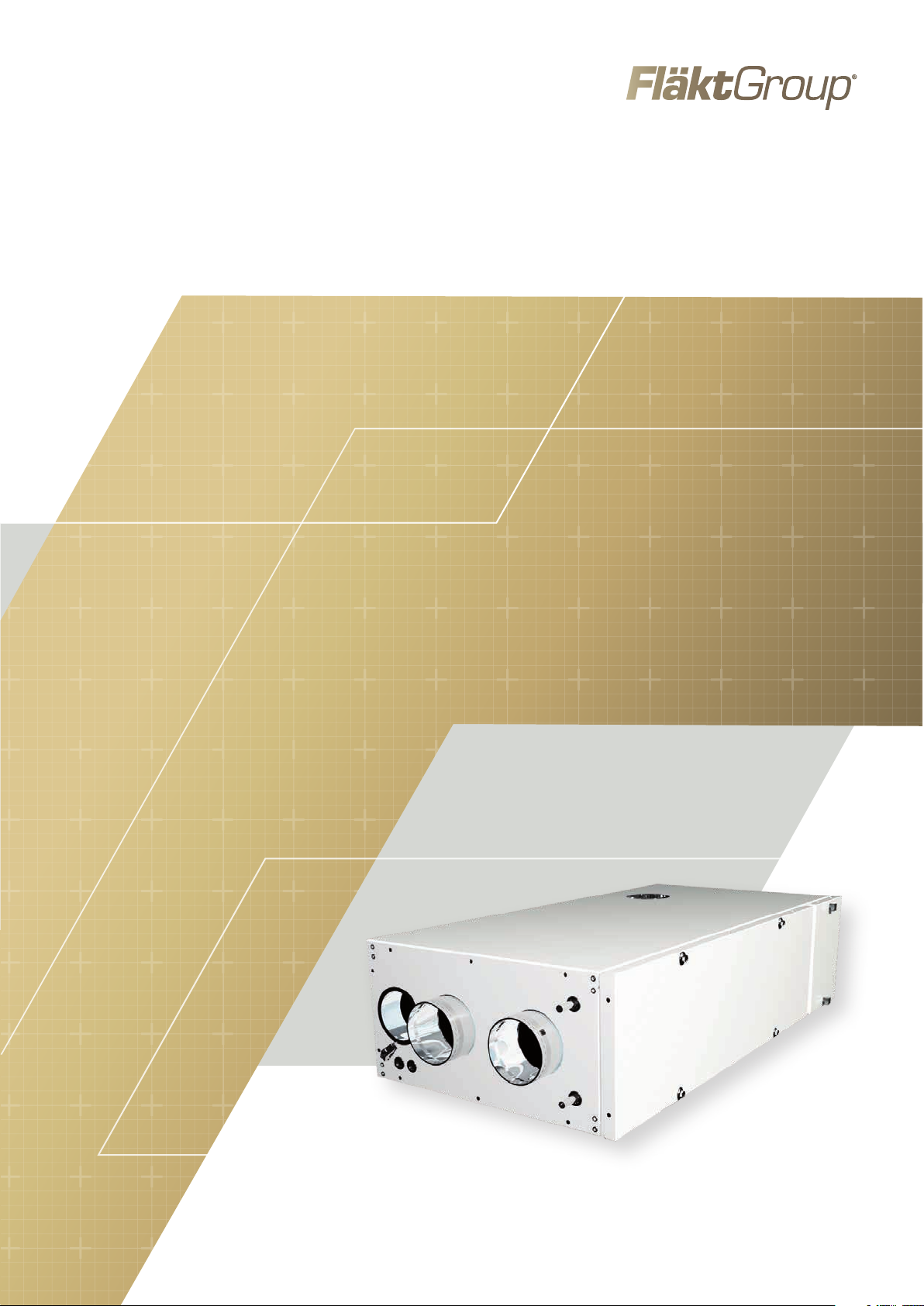
AIR HEATING UNIT
HEATMASTER ACJB
INSTALLATION, OPERATION, MAINTENANCE AND SPARE PARTS
Page 2
2
CONTENTS
OPERATION AND MAINTENANCE (FOR USER)
System, functions, main components ................................................................... 3
Control panel, operation ............................................................................................... 4
Maintenance, filter replacement ...............................................................................5
INSTALLATION (FOR INSTALLER AND SERVICE PERSONNEL)
Dismantling and installation of unit ....................................................................... 6
Capacity data ................................................................................................................... 6
Dimensions and weight ............................................................................................... 7
Connection diagrams
Unit with electric heater ...................................................................................... 8
Unit with water heater .........................................................................................9
Functions .........................................................................................................................10
Replacement of room temperature sensor (if applicable) ...........................11
ADJUSTMENT, COMMISSIONING (FOR INSTALLER AND SERVICE PERSONNEL)
Settings, Symbol descriptions ................................................................................ 12
Parameter lists .............................................................................................................. 13
Air Heating unit ACJB - Technical manual
MISCELLANEOUS
Spare parts ..................................................................................................................... 14
EC Declaration of Conformity ...................................................................................15
INFORMATION IN ACCORDANCE WITH ECODESIGN AND
REGULATION EU 2016/2281.
The ACJB is not B1, C2 or C4 air heating unit.
Type of fuel: Electricity.
Parameter Designation Value Unit
Capacity
Other
parameters
Nominal heating capacity
Minimum Capacity
Cover losses
Emission efficiency
Seasonal efficiency for
room heating
P
rated, h
P
F
h
s, flow
h
min
env
s, h
6.0 kW
0.0 kW
1.9 %
96.6 %
37.9 %
WARNING! THE APPLIANCE MAY BE USED BY CHILDREN OVER THE AGE OF 8, PERSONS (INCLUDING CHILDREN) WITH PHYSICAL,
SENSORY OR MENTAL DISABILITIES OR LACK OF KNOWLEDGE OR EXPERIENCE, PROVIDED THEY HAVE RECEIVED INSTRUCTION
OR INFORMATION ON SAFE USE OF THE APPLIANCE AND UNDERSTAND THE POTENTIAL RISKS. CHILDREN MAY NOT PLAY WITH
THE APPLIANCE. CHILDREN MAY NOT CLEAN OR PERFORM MAINTENANCE ON THE APPLIANCE WITHOUT SUPERVISION.
NOTE! INSTALLATION, ADJUSTMENT AND COMMISSIONING AS DESCRIBED
IN THESE INSTRUCTIONS MUST BE CARRIED OUT BY AN INSTALLER OR SERVICE PERSONNEL.
FläktGroup DC_9170GB_20190117_R2
We reserve the right to make changes without prior notice
Page 3
Air Heating unit ACJB - Technical manual
!
SYSTEM, FUNCTIONS, MAIN COMPONENTS
3
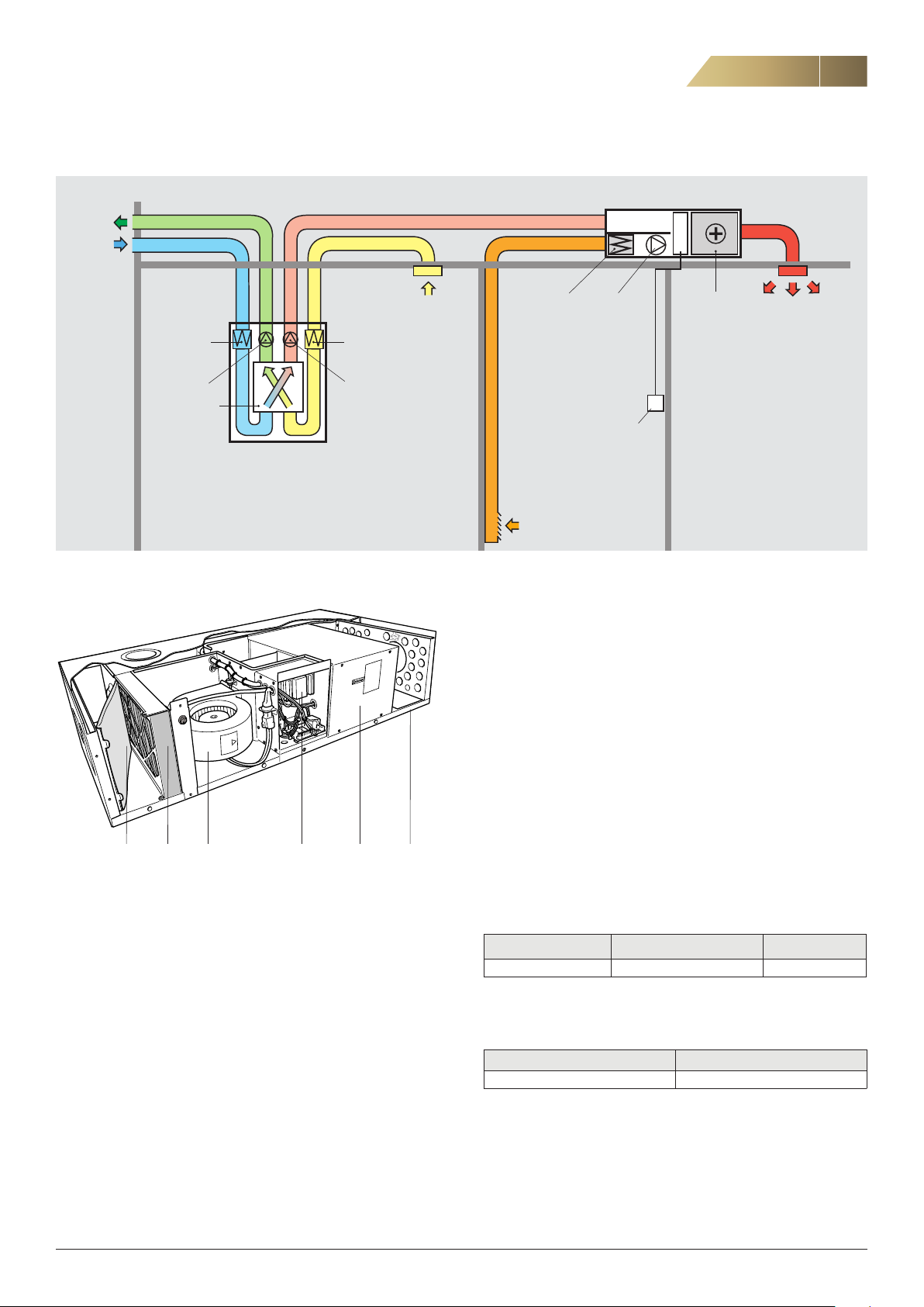
OVERVIEW OF THE AIR HEATING SYSTEM
Exhaust air
Outdoor air
Filter Filter
Fan
Heat exchanger
Heat recovery unit
THE UNIT’S MAIN COMPONENTS
Supply air
Extract air
Toilet
Bathroom
Scullery
Laundry room
Kitchen (cooker hood)
Air heating unit ACJB
Hallway
or similar
Control panel
Fan
Heater
(water/electric)
Warm supply air
Other rooms
to be heated
Filter
central area
Secondary air
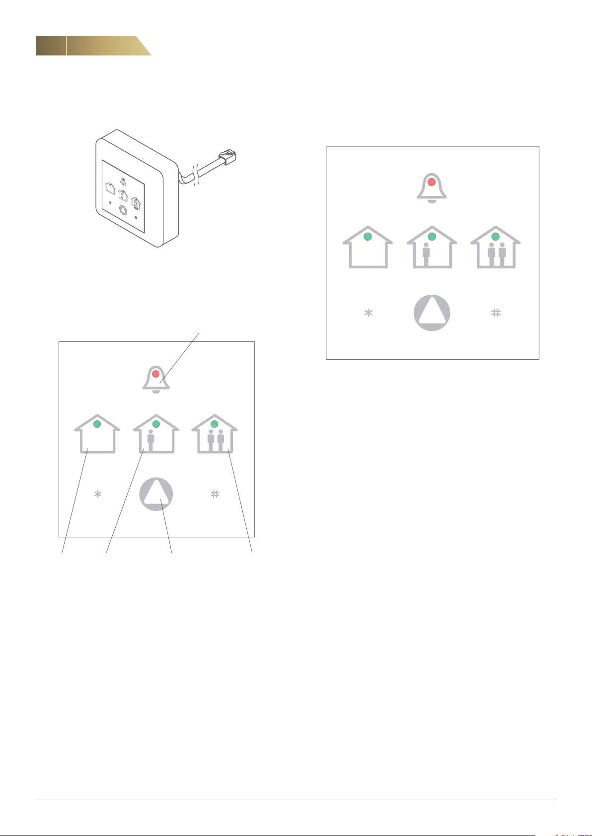
SUMMER MODE
During the summer months when there is no need for heating, summer mode can be activated. This reduces the fan operation to 30% after a set time delay (normally 24 hours). Summer mode is indicated by
a LED on the control panel.
Summer mode is automatically deactivated when there is a need for
heating.
1 2 4 5 63
1. Coarse filter (G3) ISO Coarse
2. Fine filter (M5) ISO Coarse 85%
3. Secondary air fan
4. Control unit
5. Postheater (water/electrical)
6. Casing
SYSTEM DESIGN
An air heating system combines air-based heating and balanced ventilation with heat recovery.
The heat recovery units can be installed in a kitchen, store room, scul
lery or attic.
An air heating system uses the same ducts for ventilation and heating.
CONTROL
The control unit automatically controls the ACJB unit’s fan and
water or electric heater to maintain the desired temperature.
SETTINGS
The temperature, fan speed and other parameters are set in consultation with the installer/service personnel.
ELECTRICAL DATA
UNIT WITH ELECTRIC HEATING
Voltage: 400 V, 3-phase, 50 Hz
The electric heater operates in two stages: one stage with an output of
3 kW which is controlled steplessly via a pulser, and one fixed stage
with an output of 3 kW which is controlled via a contactor.
Fan motor Output, W Electric heater Output, W Rated output, W
175 2 x 3,000 6,180
-
UNIT WITH WATER HEATING
Voltage: 230 V, 1-phase, 50 Hz
Fan motor output, W Rated output, W
175 180
FläktGroup DC_9170GB_20190117_R2
We reserve the right to make changes without prior notice
Page 4
4
CONTROL PANEL RDKZ-41-1, OPERATION
Air Heating unit ACJB - Technical manual
CONTROL PANEL RDKZ-41-1
Figure 1. Control panel RDKZ-41-1 with mains lead.
The operating mode is selected via the external control panel RDKZ-411, which should be installed in a suitable place, either on a wall or in a
wall box. Press the arrow button to select operating mode. The activat
ed mode is indicated by a LED.
FILTER ALARM
SET DESIRED TEMPERATURE
The temperature is set via control panel RDKZ-41-1.
Indicates tens
(10–90)
SUMMER MODE
NORMAL FORCED
-
Each press reduces
the set temperature
by 1 °C
Figure 3. Setting of desired temperature.
Saves the set
temperature
1. Check the current set temperature by pressing either the * or
# button once.
Then count how many times the NORMAL and FORCED symbols
flash.
Note that the NORMAL symbol indicates tens and the FORCED symbol
indicates ones.
Indicates ones
(1–9)
Each press raises
the set temperature
by 1 °C
NORMALSUMMER MODE
(for selecting operating mode)
Figure 2. Operating modes on control panel (RDKZ-41-1).
FORCEDArrow button
NORMAL MODE
The air heating unit automatically controls the fan speed to maintain
the desired temperature.
FORCED MODE
The fan goes up to maximum flow. This function can be used to distribute surplus heat through the house, for instance if a heating stove
is used.
The unit operates in forced mode for 120 minutes, and then returns to
NORMAL mode. If forced ventilation is required for only a short time, it
can be terminated manually by pressing the arrow button and select
ing NORMAL mode.
Example: If the NORMAL symbol flashes twice and the FORCED symbol
flashes three times, the temperature is currently set at 23º C.
2. To change the temperature, press * to reduce it or # to increase it.
3. After setting the desired temperature, press ARROW to save and
return to normal mode on the control panel.
-
FläktGroup DC_9170GB_20190117_R2
We reserve the right to make changes without prior notice
Page 5
Air Heating unit ACJB - Technical manual
MAINTENANCE, FILTER REPLACEMENT
5
MAINTENANCE
Wipe the unit’s casing clean with a cloth. Do not use solvents.
The filter should normally be replaced every 6 months, but sometimes
more frequent replacement is needed.
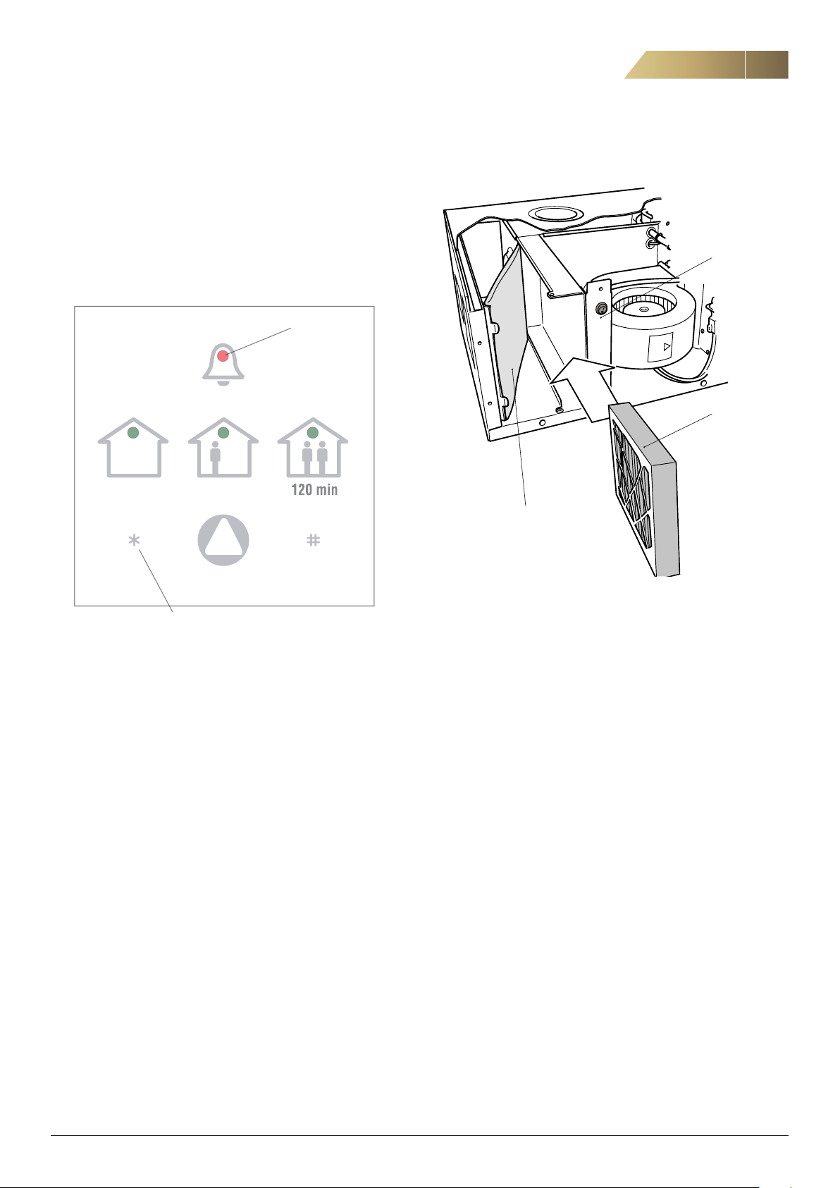
A timer is set at six months, and the alarm light on the control panel
flashes when it is time to replace the filter.
To replace the filter, follow the steps below.
Alarm light
REPLACEMENT OF FILTERS
Power switch
!
Fine filter
Coarse filter
Resetting of filter
alarm
Figure 4.
1. Switch off the unit with the power switch.
2. Open the filter hatch by turning the knobs.
3. Pull out the filters, see figure 5.
4. Insert new filters.
5. Close the filter hatch.
6. Start the unit.
7. Reset the filter alarm by pressing (*) for at least 10 seconds,
see figure 4.
Figure 5. Location of filters in unit.
FläktGroup DC_9170GB_20190117_R2
We reserve the right to make changes without prior notice
Page 6
6
!
DISMANTLING AND INSTALLATION, CAPACITY
Air Heating unit ACJB - Technical manual
DISMANTLING AND INSTALLATION
Note that the ACJB air heating unit has duct spacers, mounting screw
holes, electrical connections and, if applicable, a pipe connection for
water heating that is the same as on the previous ACJ unit.
1. Disconnect the unit from the power supply by pulling out the plug
or deactivating (removing) the fuse for the unit.
2. Disconnect the unit’s duct connections and, if applicable, the pipe
connections.
3. Disconnect the unit from the existing mounting studs, mounting
brackets and/or silencer box.
4. If there is a room sensor, also disconnect the cables from the room
sensor by opening the smaller front hatch and disconnecting them
from the circuit board.
5. Dismantle the ACJ unit.
6. If necessary, clean the secondary air and supply air ducts.
7. Mount the new ACJB unit using the existing mounting devices.
8. Connect the ducts and any pipes.
9. Replace the existing room sensor (if applicable) with the room sen
sor supplied with the new unit.
See page 9 for instructions.
10. Install control panel RDKZ-41-1 in a suitable place and connect it to
the unit.
11. Switch on the power to the unit.
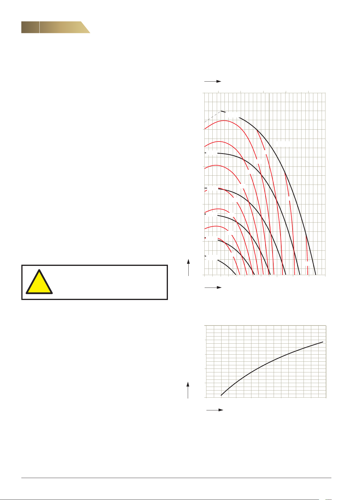
SECONDARY AIR FAN, AIRFLOW AND PRESSURE DROP
3
/h
q, m
500
400
300
Pa
∆p
200
100
s,
-
100 200 300 400 500
100%
LwA, dB
80%
70%
60%
50%
40%
58
56
54
52
50
64
62
60
66
68
THE POWER SUPPLY MUST BE SWITCHED
OFF WHILE CONTROL PANEL RDKZ-41-1 IS
BEING INSTALLED/DISMANTLED.
To prevent the air flowing in the wrong direction during defrosting, it
is recommended to connect a non-return damper between the heat
recovery unit and the air heating unit.
10
10 30 20 40 50 70 90 60 80 100 140 160 120
q, l/s
Figure 6.
HEAT OUTPUT FOR UNIT WITH WATER HEATING
4800
4600
4400
4200
W
,
P
4000
3800
0,06 0,08 0,12 0,10 0,14 0,16 0,18 0,20 0,22
qw, l/s
Figure 7.
FläktGroup DC_9170GB_20190117_R2
We reserve the right to make changes without prior notice
Page 7
Air Heating unit ACJB - Technical manual
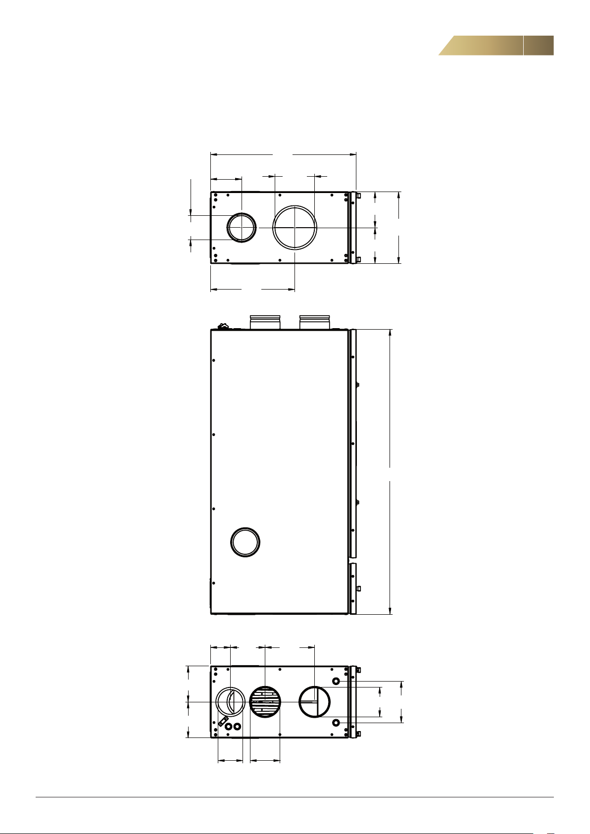
DIMENSIONS AND WEIGHT
DIMENSIONS AND WEIGHT
Weight: 55 kg
7
580
Ø100
125
Ø160
=
290
=
340
1150
80
140
200
=
168
Ø120
=
Ø120Ø100
Figure 8.
FläktGroup DC_9170GB_20190117_R2
We reserve the right to make changes without prior notice
Page 8
8
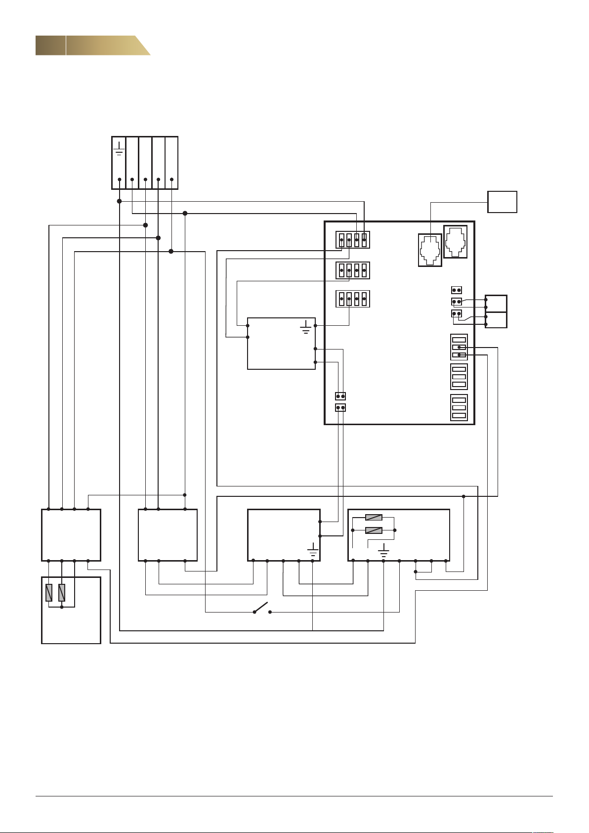
CONNECTION DIAGRAMS
UNIT WITH ELECTRIC HEATER
N L1
L2 L3
Air Heating unit ACJB - Technical manual
Control panel
17
11
9
12
10
7
5
8
6
1
4
2
3
N
L1
Fan
+10
0
V
V
33 32
31 30
16
18
19
20
21
22
23
24
25
26
27
28
29
GT
GT
Supply air
Return
1 3 5 A2 1 3 A2
Contactor
El. heater
2 4 6 A1 2 4 A1 1 2 3 4 6 5
El. heater
3-ph. 3 kW
Figure 9.
FläktGroup DC_9170GB_20190117_R2
Contactor
Pulser
Pulser
OK 1
6
5
El. heater
2-ph. 3 kW
M A
2 14 3
We reserve the right to make changes without prior notice
Page 9
Air Heating unit ACJB - Technical manual
Power supply
CONNECTION DIAGRAMS, CONT’D.
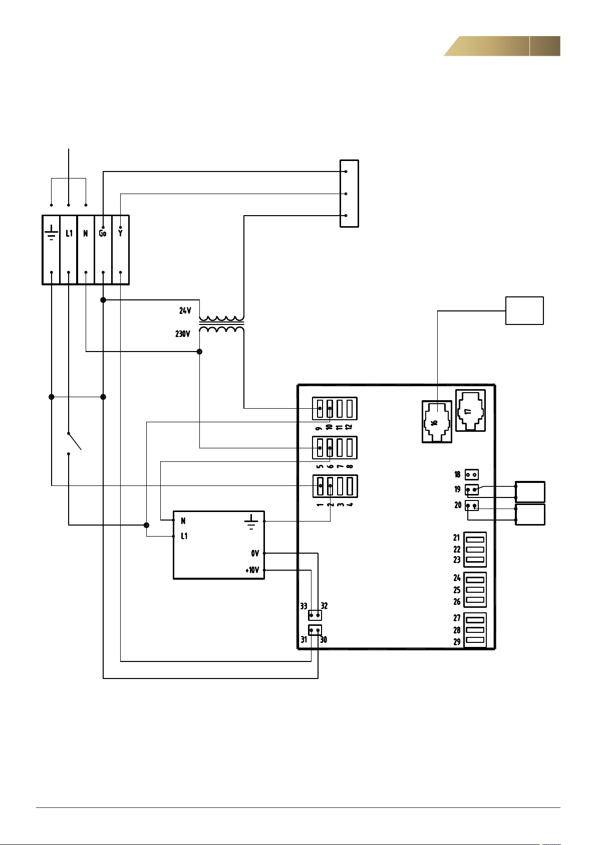
UNIT WITH WATER HEATING
9
Blue
OK
Red
Brown
Valve
Control panel
TR 1
1
Supply
air
Figure 10.
Fan
GT
GT
Return
air
FläktGroup DC_9170GB_20190117_R2
We reserve the right to make changes without prior notice
Page 10

10
FUNCTIONS, CONTROL
Air Heating unit ACJB - Technical manual
ELECTRIC HEATER 3 + 3 kW
When the heating requirement increases, the output signal to the pulser increases within a range of 0-100%. When the output signal reaches 100%, if there is still a need for increased heating, the unit will go
into plateau mode for a set time period (plateau time, default = 30 min
utes). When the plateau time ends, the fan speed will increase steplessly from MIN to 60% and a new plateau time will start. When the
plateau time ends, if there is still need for additional heating, the fixed
heating stage of 3 kW will be activated via a contactor and the pulser
will regulate the output down to 0%. After this, the pulser increases the
output steplessly from 0 till 100% while the fan speed rises from 60%
up to MAX. The heat and the fan speed are controlled in parallel.
If there is a reduced heating requirement, the pulser will reduce the
output from 100 to 0% while the fan speed drops from MAX to 60%.
When the pulser reaches 0%, the system will wait for 60 seconds. After the 60 seconds, if there is still a reduced heating requirement, the
fixed heating stage will be deactivated and the pulser regulates the
output down from 100% to 0%. When the output drops below 75%, the
fan speed will drop steplessly from 60% to MIN.
-
HIGH SUPPLY AIR TEMPERATURE
If the supply air temperature rises above 55 °C, the pulser will immediately be deactivated. When the supply air temperature drops below 55
°C, the pulser is immediately reactivated.
If the supply air temperature rises above 65 °C, the fixed heating stage
will immediately be deactivated. When the supply air temperature drops
below 65 °C, the fixed heating stage is reactivated after 60 seconds.
QUICK HEATING FUNCTION
If the temperature setpoint is set to MAX (30 °C), the fan speed and
the temperature will immediately increase to 100%. This quick heating
function is manual and has no automatic stop time or temperature
limitation.
When the desired temperature is reached, the setpoint should be reset
manually (approx. 20 °C).
SUMMER MODE
The SUMMER parameter (default = 0, off) is used to set the amount of
time that elapses before Summer mode is activated when no heating
is needed. The time delay is set in whole hours.
The recommended value is 24 hours.
When the set time (24 hours without a heating requirement) expires,
the fan speed drops to 30% (fixed fan speed). Summer mode is indi
cated by a LED on the control panel (see figure 11). When the regulator signals a demand for heating (over 5%), Summer mode is deactivated and the fan resumes Normal mode.
-
OVERHEATING
The automatic overheating protection is activated when the heater
reaches a temperature of 90 °C and is deactivated at approx. 50 °C.
The automatic overheating protection only cuts the heat supply. The fan
will continue operating.
The manually resettable overheating protection is activated when the
heater reaches a temperature of approx. 120 °C and can be reset at
approx. 75 °C. The manually resettable overheating protection cuts
both the heat supply and the fan function.
No indication is shown on the control panel if the overheating protec
tion has tripped.
-
WATER HEATER
When the heating requirement increases, the output signal to the pilot
valve increases. When the output signal reaches 50%, if there is still a
need for increased heating, the unit will go into plateau mode for a set
time period (PLATEAU TIME, default =30 min.). When the plateau time
ends, the fan speed will increase steplessly from MIN to MAX and the
heating signal will simultaneously increase from 50% to MAX. The heat
and the fan speed are controlled in parallel.
If there is a reduced heating requirement, the control valve will regulate
the output from 100 to 50% while the fan speed drops from MAX to
MIN. After this, the output signal to the control valve will continue de
creasing from 50% down to 0%.
-
SETPOINT
The setpoint can be set via the panel between +10 and +30 °C. The setpoint is always saved automatically in EEPROM, regardless of whether
it is changed via the parameter list or via quick setting.
An external potentiometer (optional accessory) can be connected to
the vacant temperature contact next to the two temperature sensors.
The board automatically detects the connected potentiometer and
reads the setpoint from it. The current setpoint can be read from the
panel, but it cannot be changed from the panel.
The potentiometer can be removed at any time, even while the pow
er is switched on. If it is removed, the function will return to the panel
(plug and play).
-
FILTER ALARM
The dirty filter alarm counts 180 days before the red light flashes. To
acknowledge the alarm, depress the left button (star) for 10 seconds.
The filter alarm is activated by default (parameter 7 = 1). The alarm can
be deactivated (parameter 7 = 2).
TEMPERATURE SENSOR MALFUNCTION
If a temperature sensor becomes faulty, the heat supply will be
blocked completely but the fan will continue operating. A temperature
error will not be indicated.
SUMMER MODE
Figure 11. Indication of SUMMER MODE.
FläktGroup DC_9170GB_20190117_R2
START-UP
On start-up, the fan will run at maximum speed for 8 seconds and
then run at NORMAL speed.
We reserve the right to make changes without prior notice
Page 11
Air Heating unit ACJB - Technical manual
REPLACEMENT OF ROOM TEMPERATURE SENSOR (IF APPLICABLE)
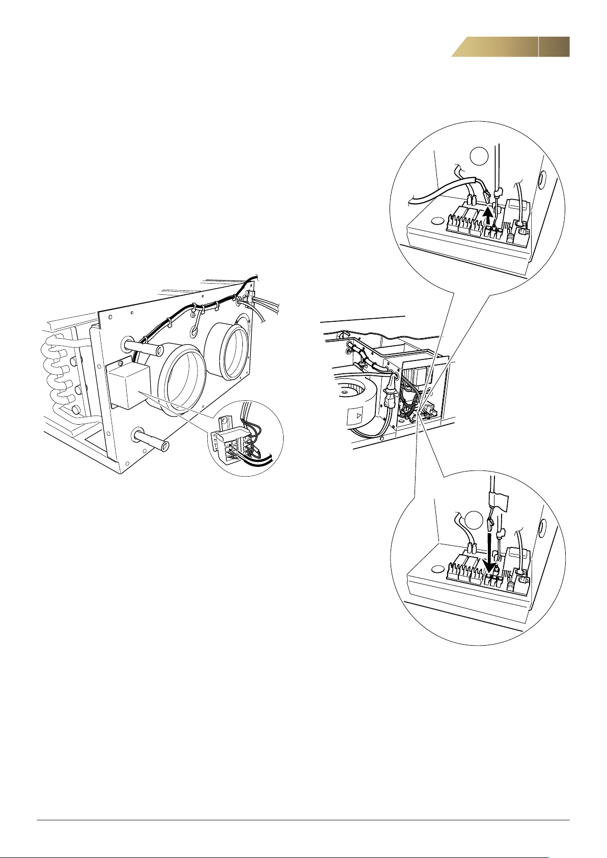
If the old ACJ unit has a room temperature sensor, the sensor cannot
be used in the new ACJB unit. A new room temperature sensor (option
al accessory) must be installed in the new unit.
1. Disconnect the unit from the power supply.
2. Remove the old room sensor.
3. Connect the room temperature sensor to the existing room temper
ature cable from the old unit.
4. Connect the room temperature cable to the junction box on the
short side of the unit (see figure 12). First remove the protective
cover. Connect the ends of the cables, then reconnect the protective
cover.
-
-
11
1
Figure 12. Junction box for cable from room temperature sensor.
5. On the control unit’s terminal block, replace the cable from the
temperature sensor
in the unit’s inlet with the cable coming out
of the junction box on the short side of the unit (the cable from the
new room temperature sensor) with the white marking
.
See figure 13.
6. Switch on the power to the unit.
!
2
Figure 13. Replacement of cable on the control unit’s terminal block.
FläktGroup DC_9170GB_20190117_R2
We reserve the right to make changes without prior notice
Page 12
12
SETTINGS, SYMBOL DESCRIPTIONS
SETTINGS
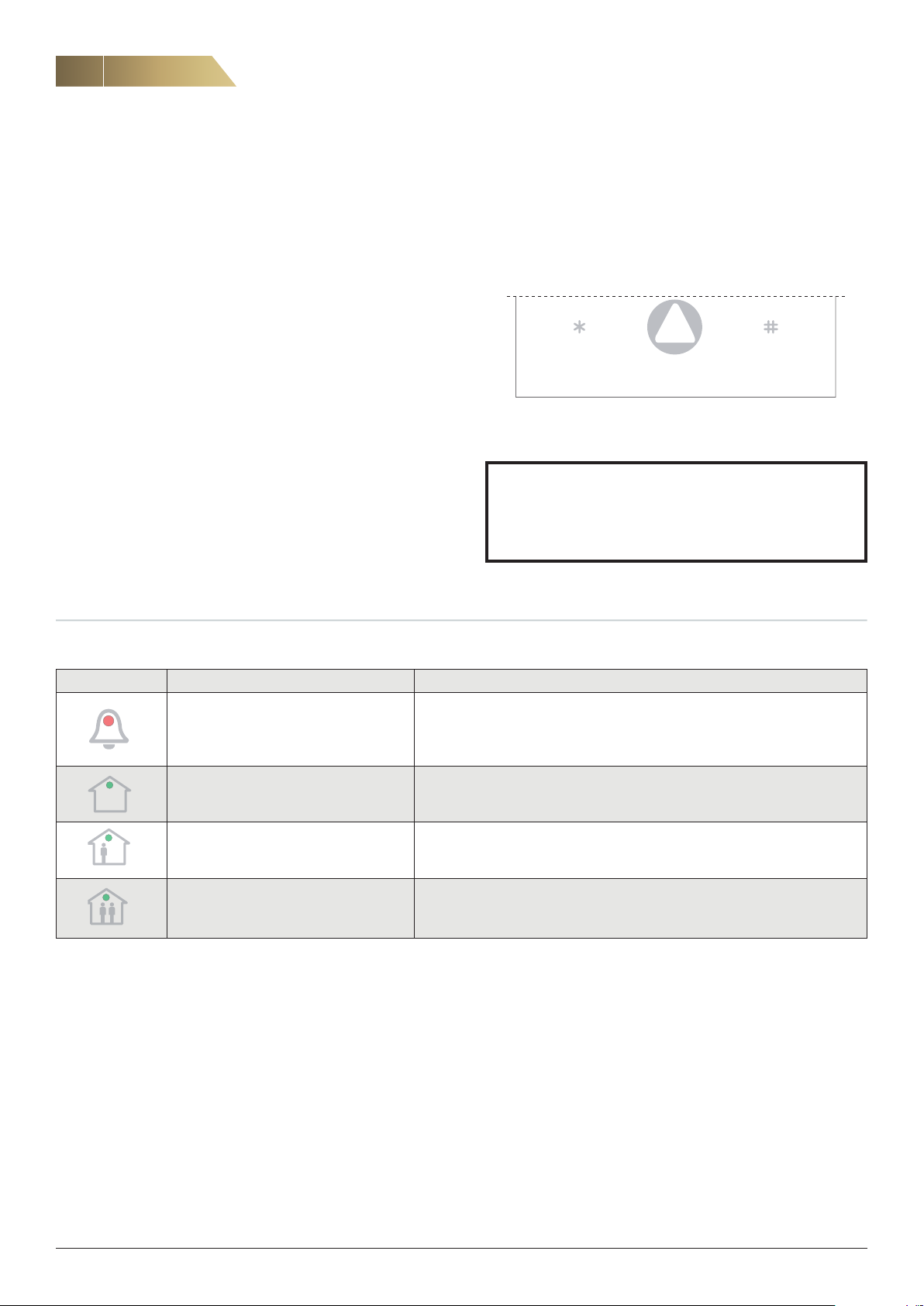
To change a parameter, follow the instructions below.
Also see the parameter list and figure 15.
1. Always start from normal operating mode.
2. Activate reading mode by depressing * and # simultaneously for
about 3 seconds.
The parameter number is illustrated by the number of times the
alarm symbol flashes. See the parameter list provided.
3. Switch between the parameters by pressing * (previous) and #
(next).
4. To change a current parameter’s value, depress * and # simulta
neously again for roughly 3 seconds until the alarm light is steadily
illuminated.
5. The parameter value can now be adjusted by pressing * (reduce)
and # (increase). The parameter value is illustrated by the number
of times the green LEDs flash (see table 16).
6. Confirm the change by pressing the ARROW button.
7. To change more parameters, repeat the procedure above.
To restore the factory settings, depress * and # simultaneously for
more than 15 seconds.
-
Air Heating unit ACJB - Technical manual
When all the LEDs flash simultaneously, confirm the reset by pressing
the arrow button.
Note: If you do not press the arrow button, only the setpoint will be re
set to 20 °C.
Lowers the set value in
programming mode
Arrow button
(CONFIRM/SAVE)
Figure 14 Symbols on display
Raises the set value in pro
gramming mode
-
NOTE! THE MINIMUM FAN SPEED MUST BE INCREASED
DEPENDING ON THE SIZE OF THE HOME.
AMONG OTHER THINGS, THIS PREVENTS THE
OVERHEATING PROTECTION FROM TRIPPING.
-
SYMBOL DESCRIPTION FOR CONTROL PANEL RDKZ-41-1 WHEN MAKING ADJUSTMENTS
Symbol Reading mode Adjustment mode
The number of times the alarm symbol
flashes indicates which parameter is
displayed. See the parameter list below.
A flashing light indicates tens A flashing light indicates tens
A flashing light indicates ones A flashing light indicates ones
Table 15.
Steady illumination indicates that adjustment mode is active and that
the current parameter value can be changed
A flashing light indicates hundreds
FläktGroup DC_9170GB_20190117_R2
We reserve the right to make changes without prior notice
Page 13
Air Heating unit ACJB - Technical manual
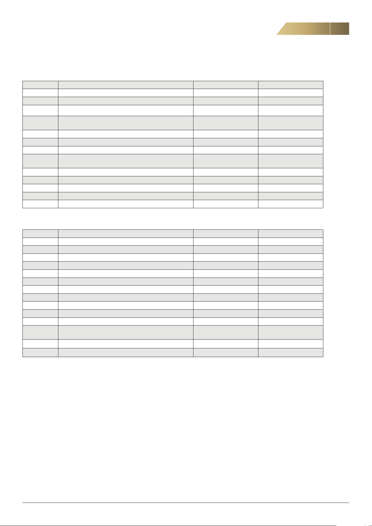
PARAMETER LISTS
ELECTRIC HEATER 3 + 3 kW
Parameter Function Setting Factory setting
1 Setpoint value supply air °C 10–30 20
2 Current temperature supply air °C Display
3 Current temperature secondary air °C Display
4
5 Adjustment MIN speed in % 40–60 40
6 Adjustment MAX speed in % 40–100 100
7 Filter alarm 1=Yes 2=No 1–2 1
8
9 Internal function – –
10 P-band multiplier 1–255 8
11 Int action time 1=5min 1–255 10
12 Current register value Display
13 Current bit information Display
Summer mode 0=no 1-255=number of hrs before acti
vation
Plateau time in minutes before changing the fan speed
and heat output
0–255 0
0–255 30
13
WATER HEATER
Parameter Function Setting Factory setting
1 Setpoint value supply air °C 10–30 20
2 Filter alarm 1=Yes 2=No 1–2 1
3 Adjustment MIN speed in % 40–100 40
4 Adjustment MAX speed in % 40–100 100
5 Current temperature supply air °C Display
6 Current temperature extract air °C Display
7 P-band multiplier 1–255 8
8 Int .action time 1=5 min. 1–255 10
9 P-band VA multiplier (not used) 1–255 8
10 Int. action time VA 1=5 min. (not used) 1–255 10
11 Range 0–200 100
12 Plateau time in minutes before changing the fan speed
and heat output
13 Summer mode (not used) 0–255
14 Control type electric/water (not used)
0–255 30
FläktGroup DC_9170GB_20190117_R2
We reserve the right to make changes without prior notice
Page 14
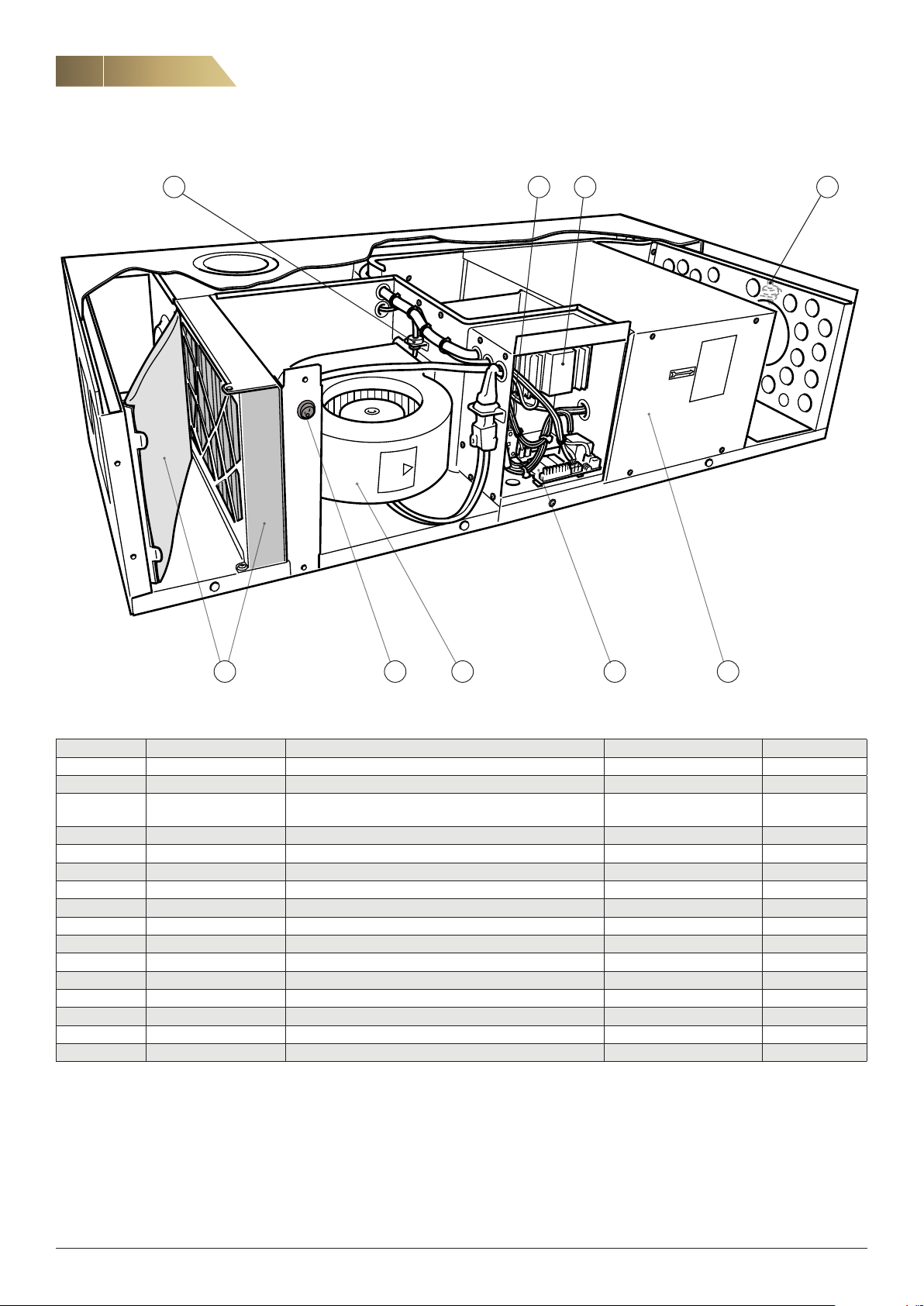
14
REPLACEMENT PARTS
Air Heating unit ACJB - Technical manual
7
!
44 8
5
21 6
3
Pos. Designation Name Included in Quantity
1 ACJZ-01 Coarse filter ACJB, (G3) ISO Coarse ACJB 5
1 ACJZ-02 Fine filter ACJB, (M5) ISO Coarse 85% ACJB 2
1 ACJZ-03 Filter kit ACJB, (G3) ISO Coarse + ((M5) ISO Coarse 85%)
ACJB 1
ISO Coarse 85%
2 ACJB-99-21 Fan, complete EC 175 W ACJB 1
3 ACJB-99-15 Control board, electric heater 3 + 3 kW ACJB-aa-b-c-1-e 1
3 ACJB-99-16 Control board, electric heater 6 kW ACJB-aa-b-c-1-e 1
3 ACJB-99-17 Control board, water heater ACJB-aa-b-c-5-e 1
4 ACJB-99-08 Temperature sensor kit, 1+1 ACJB 1
5 CPDC-99-01 Switch ACJB 5
6 ACJB-99-11 Electric heater 3 + 3 kW ACJB-aa-b-c-1-e 1
*)
6 ACJB-99-12 Electric heater 6 kW
(conversion kit 3 + 3 kW) ACJB-aa-b-c-1-e 1
6 ACJB-99-02 Water heater ACJB-aa-b-c-5-e 1
7 ACJB-99-05 Pulser ACJB-aa-b-c-1-e 1
8 ACJB-99-06 Contactor ACJB-aa-b-c-1-e 1
9 ACJB-99-03 Valve actuator ACJB-aa-b-c-5-e 1
10 ACJB-99-07 Transformer 230/24V ACJB-aa-b-c-5-e 1
*)
Electric heater 6 kW has been discontinued. It has been replaced with electric heater 3 + 3 kW including conversion kit.
If the supply cord is damaged, it must be replaced by the manufacturer, an authorised service firm or a similarly qualified professional
in order to avoid hazard.
FläktGroup DC_9170GB_20190117_R2
We reserve the right to make changes without prior notice
Page 15

Page 16

WWW.FLAKTGROUP.COM HEATMASTER ACJB
FläktGroup is the European market leader in smart, energy-efficient ventilation
systems for optimal indoor comfort, critical applications and fire safety. Our
products and solutions are based on innovative technology, high quality and
superior performance, backed by over 100 years of experience in the industry.
With the market’s widest range of products and strong market presence in
65 countries worldwide, we are always close to you – with a clear focus
on delivering Excellence in Solutions.
FG_DC_9170GB_Heatmaster ACJB_IN-MA-CM-SP_20190117_R2 © Copyright 2019 FläktGroup J8016030-2301
FLÄKTGROUP PRODUCT AREAS
Air Treatment | Air Movement | Air Distribution | Chilled Beams
& Chilled Beam Cassettes | Air FiltrationAir Management & ATDs
| Air Conditioning & Heating | Control | Service
» Learn more on www.flaktgroup.com
or contact one of our offices
 Loading...