

Page 1
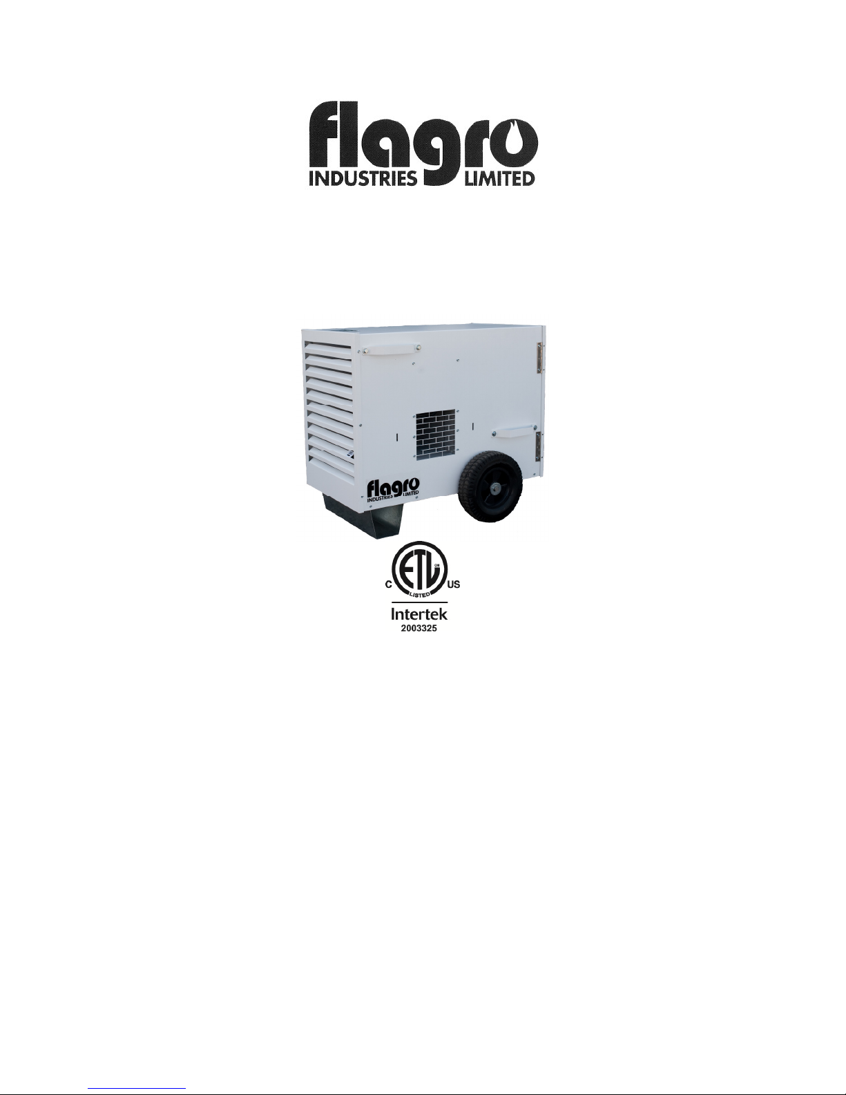
THC 85N
INDUSTRIAL / COMMERCIAL SPACE
HEATER
Certified to / Certifié à CGA 2.14 M2000 Conforms to / Conforme à ANSI std
Z83.7 2000
Suitable for indoor or outdoor installation / Unvented / Unattended Type
OPERATING INSTRUCTIONS MANUAL
SPECIFICATIONS:
Model ………………………………………………….. THC-85N
Input ……………………………………………………… 85,000 BTUH
Fuel ………………………………………………………. Natural Gas
Inlet Pressure …………………………………………… 7.0” W.C.
Ignition ………………………………………………… Direct Spark Ignition
Thermostat Control………………………………………Standard
Air Circulation ……………………………………………700 cfm
Fuel Consumption………………………………………. 82 cfh
Approved…………………………………………………. cETLus listed
THC-85N OPERATING INSTRUCTIONS MANUAL
1
Page 2

! GENERAL HAZARD WARNING:
FAILURE TO COMPY WITH THE
PRECAUTIONS AND INSTRUCTIONS
PROVIDED WITH THIS HEATER, CAN
RESULT IN DEATH, SERIOUS BODILY
INJURY AND PROPERTY LOSS OR
DAMAGE FROM HAZARDS OF FIRE,
EXPLOSION, BURN ASPHYXIATION,
CARBON MONOXIDE POISONING, AND /
OR ELECTRICAL SHOCK.
ONLY PERSONS WHO CAN UNDERSTAND
AND FOLLOW THE INSTRUCTIONS
SHOULD USE OR SERVICE THIS HEATER.
IF YOU NEED ASSISTANCE OR HEATER
INFORMATION SUCH AS AN
INSTRUCTIONS MANUAL, LABEL, ETC.
CONTACT THE MANUFACTURER.
! WARNING: FIRE, BURN, INHALATION,
AND EXPLOSION HAZARD, KEEP SOLID
COMBUSTIBLES, SUCH AS BUILDING
MATERIALS, PAPER, OR CARDBOARD, A
SAFE DISTANCE AWAY FROM THE
HEATER AS RECOMMENDED BY THE
INSTRUCTIONS. NEVER USE THE HEATER
IN SPACES WHICH DO OR MAY CONTAIN
VOLATILE OR AIRBORNE COMBUSTIBLES,
OR PRODUCTS SUCH AS GASOLINE
SOLVENTS, PAINT THINNER, DUST
PARTICLES OR UNKNOWN CHEMICALS.
! WARNING: NOT FOR HOME OR
RECREATIONAL VEHICLE USE.
2
Page 3

WARNING:
This heater is designed and approved for use in accordance with Standard ANSI
Z83.7-CGA 2.14. CHECK WITH YOUR LOCAL FIRE SAFETY AUTHORITY IF
YOU HAVE QUESTIONS ABOUT APPLICATIONS.
Other standards govern the use of fuel gases and heat producing products in
specific applications. Your local authority can advise you about these.
FOR TEMPORARY HEAT ONLY.
FOR USE WITH NATURAL GAS ONLY.
DO NOT OPERATE IN A CLOSED OR CONFINED SPACE.
ALWAYS PROVIDE ADEQUATE VENTILATION. AIR SUPPLY – MUST BE
FRESH AIR FROM OUTDOORS OR ADEQUATE INDOOR SUPPLY.
DO NOT USE OR STORE GASOLINE OR FLAMMABLE VAPOURS OR
LIQUIDS IN THE VICINITY OF THE HEATER.
HEATER MUST BE INSTALLED ON A LEVEL SURFACE.
INSTALLATION:
The installation of this heater shall conform with local codes or, in the absence of
codes with the National Fuel Gas Code ANSI Z223.1/NFPA 54 and the Natural
Gas and Propane Installation Code, CSA B149.00. This heater must be installed
by a qualified gas technician, following local codes published by the authority
having jurisdiction.
PIPING: This heater must be installed by a qualified gas technician
following local codes published by the authority having
jurisdiction. Sizing of supply piping must be determined
using the length of pipe run as well as total btuh rating of the
appliance(s). Appropriate piping tables must be used to
determine size of supply piping dependant on the length of
run from source.
PRESSURES: MAXIMUM INLET PRESSURES: NG: 7.0 IN. WC.
MINIMUM INLET PRESSURES: NG: 7.0 IN. WC.
This heater must be supplied by pressures indicated on the
approval label. Over pressure may cause controls to fail.
3
Page 4

DO NOT supply this unit with more than 7.0 in. W.C.)
FUEL: This heater will operate on natural gas only. The manifold pressure is
listed on the approval label and the proper have been provided. Ensure the
supply pressure is correct before attempting to light the heater. Any replacement
parts must be purchased from the manufacturer or authorized distributor.
HOSES: All hoses used to connect this heater of fuel supply must be Type 1
approved propane / natural gas hose assemblies.
ELECTRICAL: WARNING Electrical Grounding Instructions
This appliance is equipped with a three-prong (grounding) plug for your
protection against shock hazard and should be plugged
directly into a properly grounded three-prong receptacle.
120v supply must be available. Please note that the motor
on this unit requires 20 amps. Ensure appropriate gauge
extension cord is used.
CLEARANCE TO COMBUSTIBLES:
TOP – 2 ft FRONT – 8 ft SIDES – 2 ft REAR – 1 ft
DUCTING
Manufacturers ducting must be used on this heater. Flagro part number
THCP-WD12 (12” x 12 FT Hitex
A MAXIMUM OF 12 FT OF DUCTING ONLY
4
Page 5

POWER SUPPLY INDICATOR LIGHT:
The power supply indicator light will help detect any faulty power supplied to the
heater such as; grounding issues, reverse polarity or missing/poor connections.
Warning Light Indications
Green Light ……………… Meets Power Requirements
Solid Red Light………….. Reverse Polarity
Solid Red & Green Light… Ground Issue
ATTENTION: IF SOLID RED & GREEN IS INDICATED, MAKE CORRECTIONS
TO POWER SUPPLY BEFORE TURNING HEATER ON. FAILURE TO DO SO
WILL VOID ANY WARRANTY.
MAINTENANCE:
1. Every heater should be inspected before each use.
2. Heaters must be inspected annually by a qualified service person.
3. The hose assembly shall be visually inspected prior to each use of the heater.
If it is evident there is excessive abrasion or wear, or the hose is cut, it
must be replaced prior to the heater being put into operation. The
replacement hose assembly shall be that specified by the manufacturer.
4. The appliance must be kept clear and free from combustible materials,
gasoline and other flammable vapors and liquids.
5. The flow of combustion and ventilation air must not be obstructed. Be sure to
check the fan assembly and ensure the motor and blade are operating
properly.
6. Compressed air should be used to keep components free of dust and dirt build
up. Note: Do not use the compressed air inside any piping or regulator
components.
5
Page 6

START UP INSTRUCTIONS:
1. Ensure the heater is provided with a gas supply of 7.0” W.C.
2. Open the gas supply.
3. Depress the fan switch to the “ON” position. The fan motor will start and air
will be pushed through the outlet of the heater.
4. Depress the burner switch to the “ON” position. The burner should ignite and
hot air will be pushed through the outlet of the heater.
5. Set the Thermostat (if provided) to desired temperature.
6. If heater fails to ignite after 3 attempts call your supplier for service.
TO SHUT DOWN:
1. Close the gas supply valve.
2. Move both the “FAN” and “BURNER” switches to the “OFF” position.
3. Disconnect heater from the gas supply.
02/08/17
6
Page 7
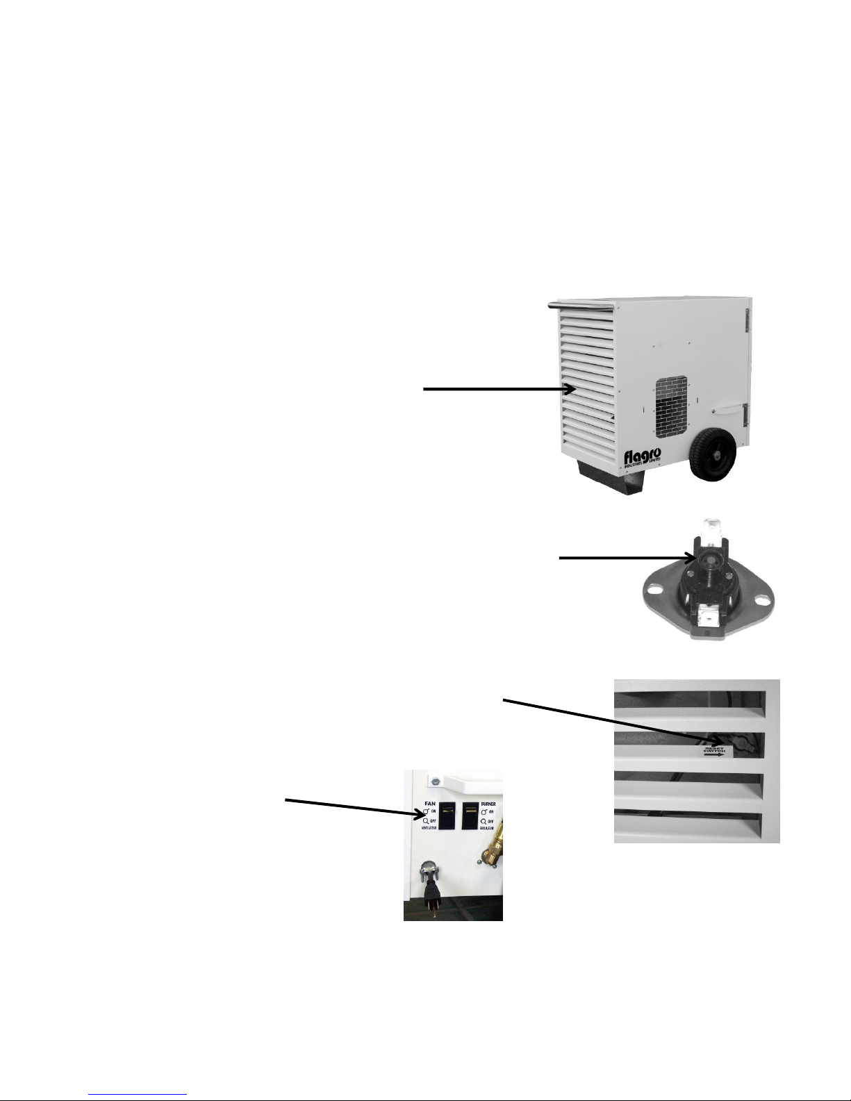
THC-85 SERIES TROUBLESHOOTING ANALYSIS
PLEASE NOTE: In order to facilitate trouble shooting, unit panels have been removed in some of these
pictures for ease of identification only. All panels and fasteners must be in place as provided by the
manufacturer to ensure the safe and efficient operation of this gas fuelled appliance.
PROBLEM: NO HEAT, FAN OPERATES.
POSSIBLE CAUSE: Rear of heater is blocked.
REMEDY: Ensure rear of heater is unobstructed
and proper rear clearances are maintained.
(see approval label for specifications)
POSSIBLE CAUSE:If the rear of the heater is obstructed, the snap
disc manual reset limit may trip and must be
reset manually before the fan can operate.
REMEDY: The high temperature limit switch reset button
is found behind the louvers on the rear of the heater,
DISCONNECT THE POWER TO THE HEATER.
Use a non-metallic slim tool, insert carefully through
louver opening and push the “red” button to reset the
switch OR remove the louvered rear panel door and
push the “red” reset button. Make certain to re-close
the panel before operating the appliance.
POSSIBLE CAUSE:Faulty On-Off switch.
REMEDY: Replace the switch.
Page 8
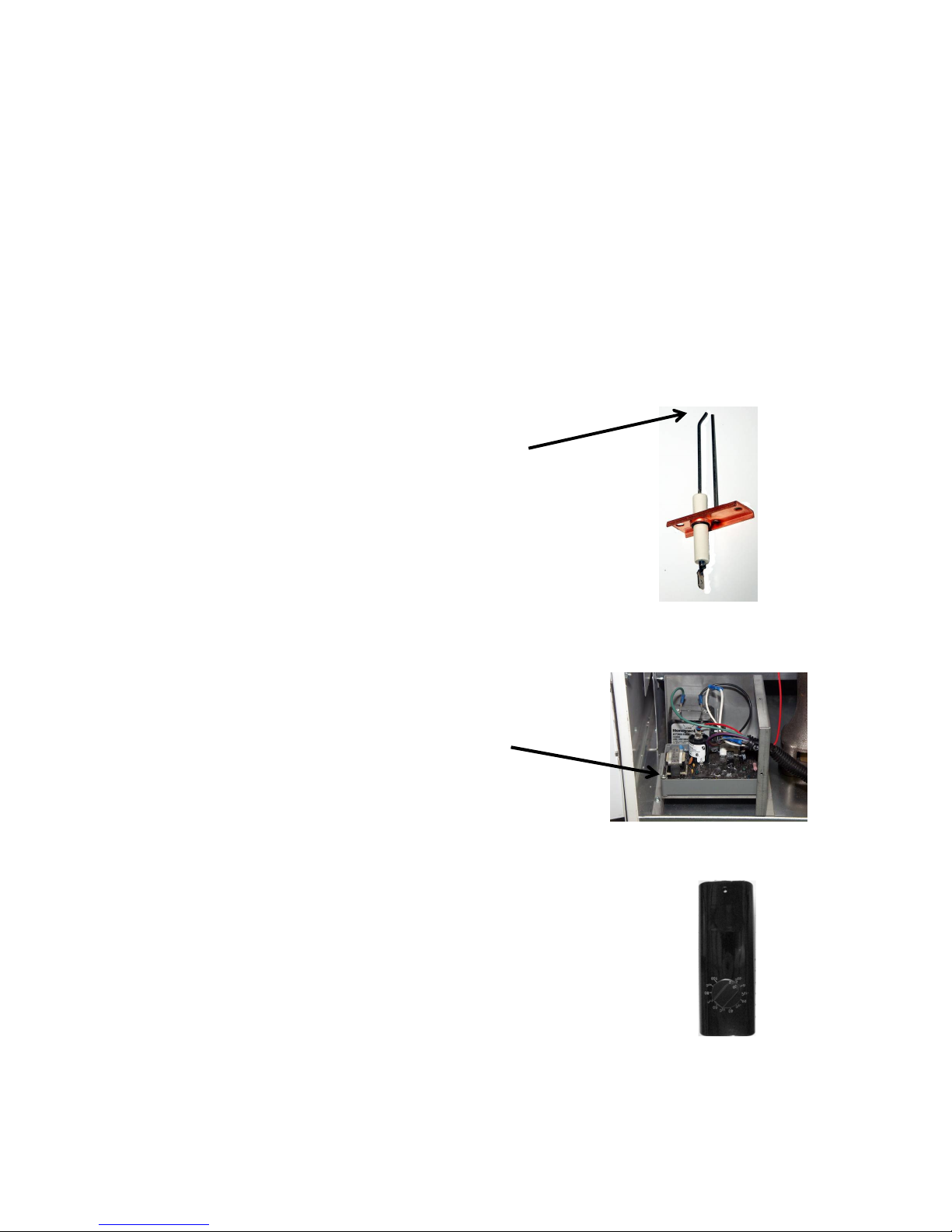
PROBLEM: HEATER WILL NO LIGHT.
POSSIBLE CAUSE: Gas Supply.
REMEDY: Ensure required gas supply pressures are available to the heater.
(see approval label for specifications).
POSSIBLE CAUSE: Gas Valve / Solenoid.
REMEDY: Ensure solenoid is energized. (use volt meter).
Ensure plunder in solenoid is being activated. (use manometer at test point after solenoid).
=
POSSIBLE CAUSE: Igniter / Flame Sensor
REMEDY: Ensure the gap between the igniter and sensor is
approximately 1/8” – 3/16”. DO NOT adjust the
porcelain side of the igniter as permanent damage
may result.
Check igniter wire connections.
Ensure igniter spark is strong.
Replace igniter assembly if necessary.
POSSIBLE CAUSE: Ignition Board.
REMEDY: Ensure electrical signals for igniter and gas valve /
solenoid are present.
Ensure ignition board is properly grounded.
POSSIBLE CAUSE: Thermostat.
REMEDY: Ensure that the thermostat is calling for heat (if it is,
the fan will start). Please not that as a safety measure
the thermostat is equipped with a 10 second delay.
If your heater is equipped with an optional external
thermostat check that connections are secure and restart
the heater. If the heater fails to restart, remove the optional
line thermostat and restart the heater to confirm operational
status. If the heater starts, replace the thermostat.
Page 9
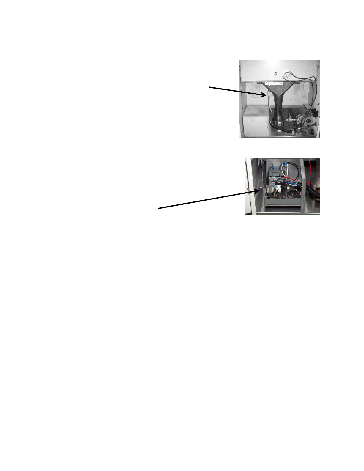
PROBLEM: HEATER WILL NOT REMAIN LIT AFTER START UP.
POSSIBLE CAUSE: Faulty igniter wire.
REMEDY: Check igniter wire for any damage. Replace is necessary.
POSSIBLE CAUSE: Faulty igniter / flame sensor.
REMEDY: Ensure connections are secure. Replace igniter / flame
sensor if necessary.
POSSIBLE CAUSE: Ignition board.
REMEDY: Check ground wire for proper connection.
Check polarity of extension cord compared to polarity
of plug on the heater.
Replace faulty ignition board.
POSSIBLE CAUSE: Thermostat.
REMEDY: Ensure thermostat is calling for heat. NOTE: If the
thermostat is not calling for heat, the heater will not operate.
PROBLEM: ELECTRICAL.
POSSIBLE CAUSE: All components.
REMEDY: Before replacing any component, all connections must be checked to ensure the
electrical circuit is complete. (Use volt meter and enclosed wiring diagram).
Any point in the circuit where 120v is not achieved indicates location of problem
and/or possible faulty component. NOTE: Everything downstream of the
transformer is 24v (eg. all switches and sensors).
PROBLEM: PIPING.
POSSIBLE CAUSE: All pipe fittings.
REMEDY: When loosened, tightened or replaced, the complete fitting should be removed
and approved pipe sealant applied to all male threads before reconnection
Page 10
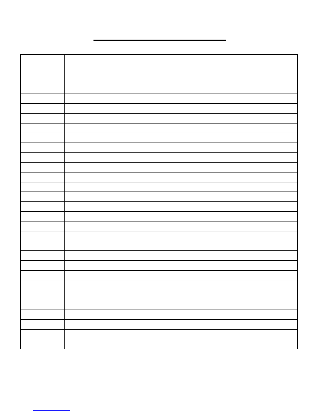
PARTS LIST FOR THC-85N
Part Number Part Description
THCP-101 CAST IRON BURNER
THCP-102 IGNITER/ FLAME SENSOR ASSEMBLY
THCP-103 IGNITER WIRE
THCP-104 120/24 VOLT TRANSFORMER
THCP-105 GAS VALVE / SOLENOID - 24V
THCP-106A IGNITION CONTROL - 120V
THCP-107A WIRING HARNESS FOR THCP-106A
THCP-108A HIGH TEMPERATURE LIMIT (OUTLET) CURRENT
THCP-109 HIGH TEMPERATURE LIMIT (BURNER)
THCP-110 AIR PROVING SAIL SWITCH
THCP-111 MAIN BURNER OR FAN SWITCH
THCP-113 MOTOR
THCP-114A FAN BLADE - THC-85
THCP-118 ORIFICE FOR THC-85NG
THCP-119 ORIFICE HOLDER
THCP-120 1/4" X 4 1/2" NIPPLE
THCP-120A 1/4" X 3" NIPPLE
THCP-121 ELECTRICAL SUPPLY CORD
THCP-122 SIDE HANDLES (EACH) TWO REQUIRED
THCP-123 REAR HANDLE
THCP-124 W HEELS - 10" (EACH) TWO REQUIRED
THCP-125S WHEEL SHAFT - THC-85
THCP-126A REAR FOOT - THC-85
THCP-131 TENT HEATER DOOR LATCH (EACH)
THCP-132 DOOR HINGE (EACH) TWO REQUIRED
THCP-154A POWER INDICATOR LIGHT - AS OF 2014
THCP-8510 BODY PANEL FOR THC-85
THCP-8511 FRONT DOOR FOR THC-85
THCP-8512 REAR PANEL FOR THC-85
Page 11
THCP-WD12 WHITE DUCT 12" X 10FT
THCP-DA12 DUCT ADAPTER
THCP-DD DUCT DIFFUSER
THCP-HD85 HEAT DIFFUSER
THCP-TH THERMOSTAT KIT
ACCESSORIES
 Loading...