

Page 1
OPERATING INSTRUCTIONS MANUAL
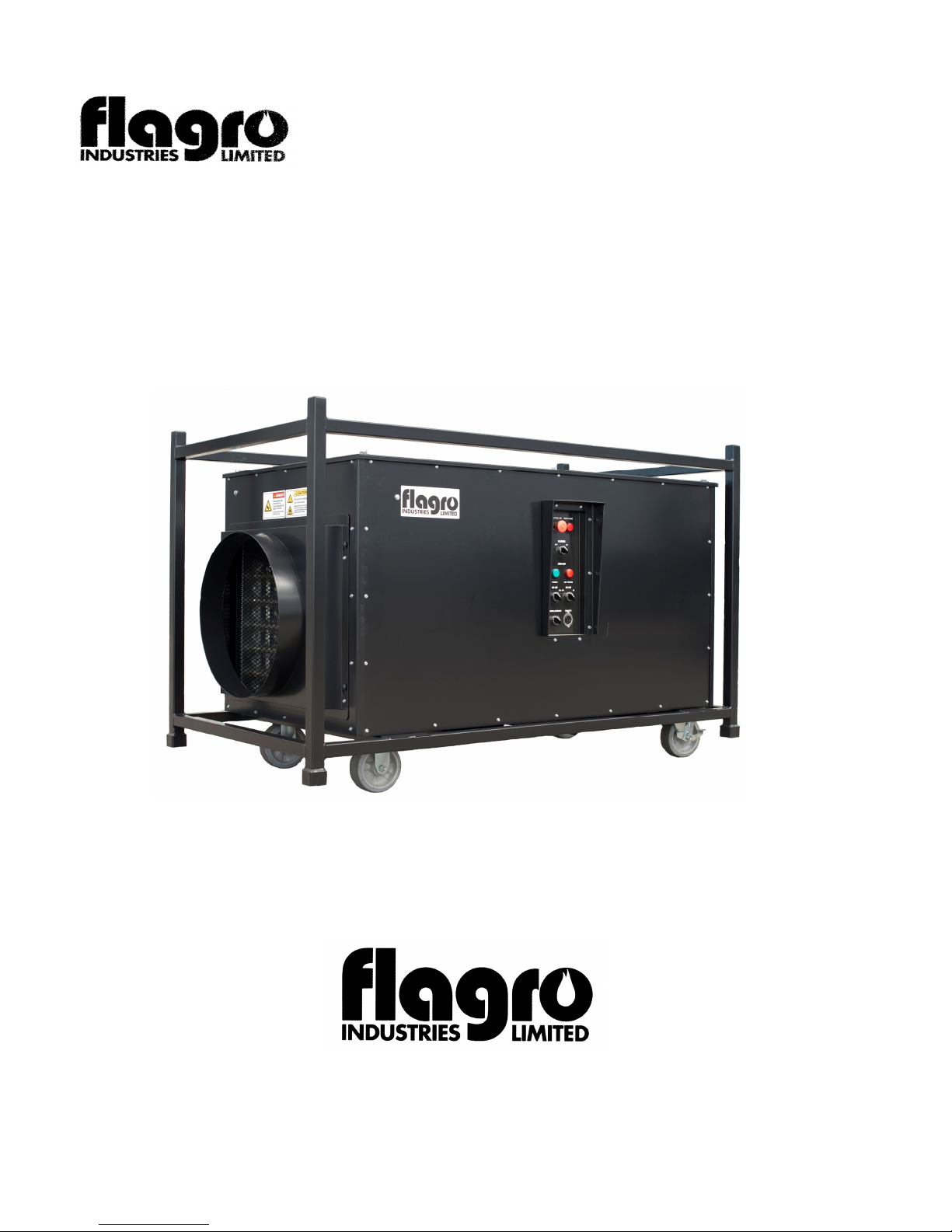
INDUSTRIAL / COMMERCIAL ELECTRIC HEATER
FLE-150
(OPERATOR MUST RETAIN FOR FUTURE REFERENCE)
Suitable for indoor or outdoor installation / Unvented / Unattended Type
26 Benfield Drive, St.Catharines, Ontario Canada L2S 3V5
(P) 905-685-4243 - (F) 905-685-0113
Page 2

FLE-150 OPERATING INSTRUCTIONS MANUAL
GENERAL HAZARD WARNING:
FAILURE TO COMPLY WITH THE PRECAUTIONS
AND INSTRUCTIONS PROVIDED WITH THIS
HEATER, CAN RESULT IN DEATH, SERIOUS
BODILY INJURY AND PROPERTY LOSS OR
DAMAGE FROM HAZARDS OF FIRE, EXPLOSION
BURN ASPHYXIATION, OR ELECTRICAL SHOCK
ONLY PERSONS WHO CAN UNDERSTAND AND
FOLLOW THE INSTRUCTIONS SHOULD USE OR
SERVICE THIS HEATER.
IF YOU NEED ASSISTANCE OR HEATER
INFORMATION SUCH AS AN INSTRUCTIONS
MANUAL, LABEL, ETC. CONTACT THE
MANUFACTURER
WARNING: FIRE, BURN, INHALATION
AND EXPLOSION HAZARD, KEEP SOLID
COMBUSTIBLES, SUCH AS BUILDING
MATERIALS, PAPER, OR CARDBOARD, A SAFE
DISTANCE AWAY FROM THE HEATER AS
RECOMMENDED BY THE INSTRUCTIONS
NEVER USE THE HEATER IN SPACES WHICH DO
OR MAY CONTAIN VOLATILE OR AIRBORNE
COMBUSTIBLES, OR PRODUCTS SUCH AS
GASOLINE SOLVENTS, PAINT THINNER, DUST
PARTICLES OR UNKNOWN CHEMICALS
WARNING: NOT FOR HOME OR
RECREATIONAL VEHICLE USE
Page 3

Introduction
You have just received an FLE-150 150kW Electric Construction Heater manufactured by Flagro Industries.
Quality
: The FLE-150 is built with the highest quality of components, giving our
Convenience:
The FLE-150 gives our customers the flexibilty of a 60kW/90kW/150kW heat setting.
Use: The FLE-150 Electric Construction Heater is designed for temporary heat only.
The heater may be installed indoors or out and used to bring 100% outdoor air, or heat
and re-circulate building air. The FLE-150 is designed to heat large spaces, buildings
and machines without worrying about on site fuel.
customers the confidence they deserve in a Flagro product.
The heater is equipped with a; fan speed inverter control that provides optimum temperature rise
by adjusting blower output at each heat setting. Colour coded Cam Lock power connections
for easy installation. Remote thermostat option available.
Safety
Always verify that you have proper voltage supply. (480V) It is important to check
the wiring connections inside the heater before plugging in the Cam Locks.
Use a meter to measure volt supply to each cam lock.
Work on the internal systems should only be attempted by a certified electrician and
only when power has been disconnected and can not be reconnected to the heater.
Grounding
The heater is supplier with a cam lock system with a grounding connection and is indicated with a "G"
on the cam lock panel. The heater is also supplied with a grounding nuts found on all panels.
It is very important to double check that all grounding connections are properly secure.
Clearance from Combustibles
The discharge temperature of these units may reach very high temperatures. Maintain minimum
distance from combustible materials as follows:
Top: 6 Inches
Bottom: 6 Inches
Sides: 6 Inches
Discharge: 15 FT
Page 4

MAINTENANCE
1 Every heater should be inspected before each use, and at least annually by a
qualified service person
2 The appliance must be kept clear and free from combustible materials,
gasoline and other flammable vapors and/or liquids
3 The flow of ventilation air must not be obstructed.
Be sure to check the fan assembly and ensure the motor and blade
are operating properly.
4 Compressed air may be used to keep components free of dust and dirt
build up.
Pre-Start Checklist
1
Heater must be level and lockable wheels must be in the lock position
2
Make sure blower switch and both heat selection switches are in the
"OFF" positions
3
Make sure the air intake is free from any obstruction(s)
4
Make sure the heater oulet is free from any obstruction(s)
5
Make sure the heater is properly grounded
6
Check power supply voltage and ampacity
Page 5
START UP INSTRUCTIONS
1 Determine power source - 480V (confirm power source is correct)
2 Remove top cover and inspect all wiring
(once complete, secure top cover to heater using the same hardware)
3 Connect Flanged Camlocks to female camlocks ( colour coded)
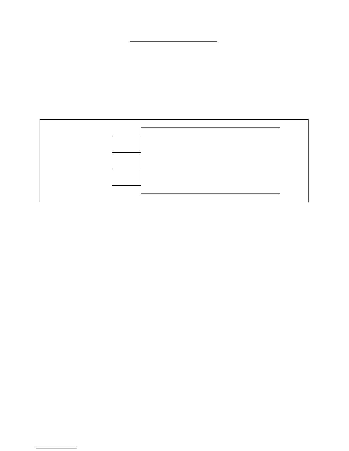
Connect camlocks as follows:
Red A
Black B
Blue C
Ground G
3 PHASE UNIT CONNECTION
4 Turn on power supply
5 Pull "Master" button to the out position
6 Determine "Manual" or Remote Thermostat (if remote, set desired temperature)
7 Turn Blower on/off switch to the "ON" position
(The blower will start and the green air flow light will come on)
8 Turn on heater settings as desired
( 150kW= 60kW & 90kW combined)
Failure to have proper air flow will cause unit to overheat and shut down
The green light should come on and air should be pushed through the outlet port
Check to see that only the green light is on.
Caution: Heater body panels will get very hot
Page 6
Notes:
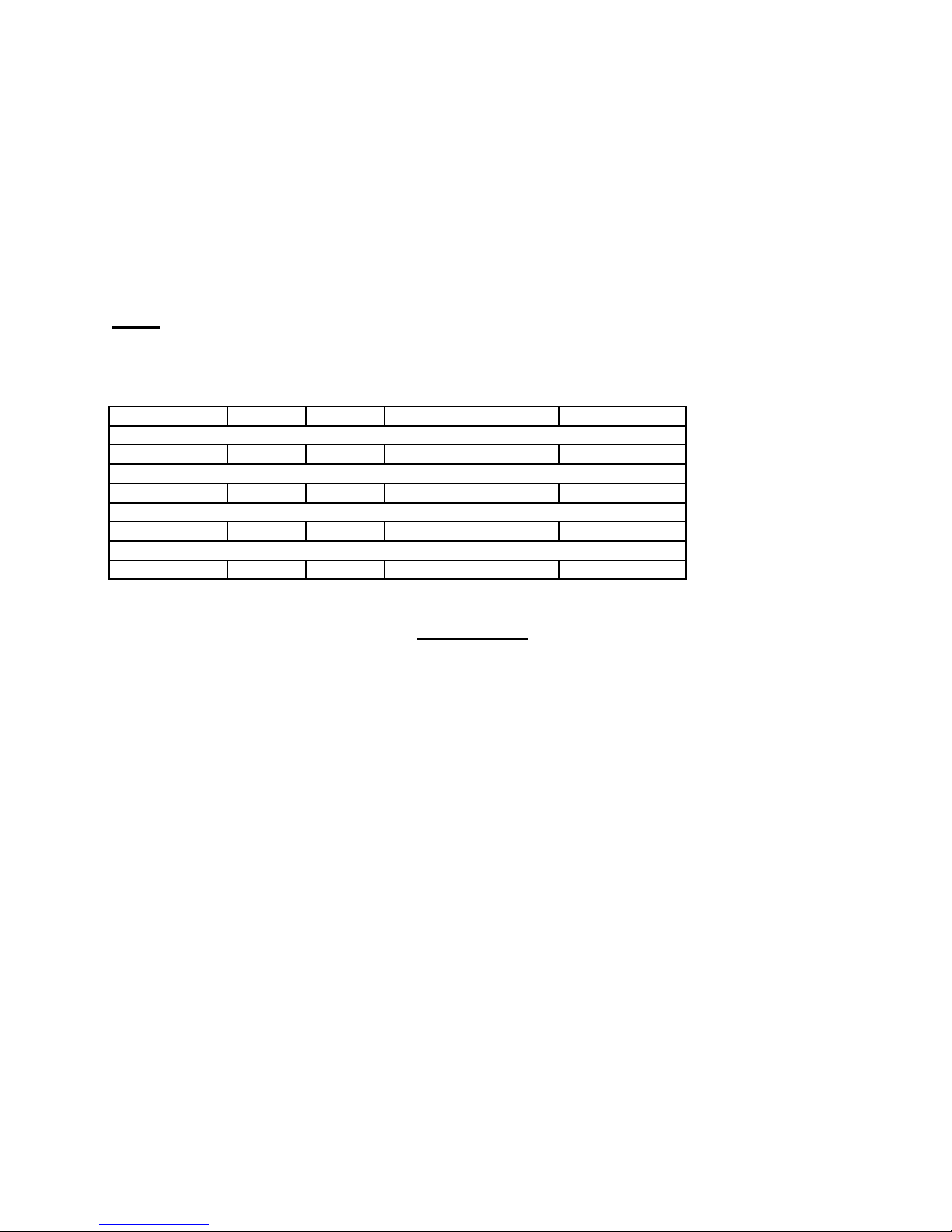
Speed inverter is pre-set for optimum air flow/temperature rise.
HEAT SETTING
BTUH
CFM
TEMP. RISE
NOISE RATING
1
2
3
4
5
6
7
Based on kW selection, blower will adjust speed. See Chart below
150 kW 512,000 5300 138F 79 DB
90 kW 307,000 4650 101F 76 DB
60kW 205,000 4100 67F 73 DB
FAN ONLY 6800 N/A 85 DB
SHUTDOWN
Move all heat control setting to the "OFF" position
Leave Fan in the "ON" position for 3-5 minutes
Turn Fan OFF
( blower is preset to run for 30 seconds before coming to a complete stop)
Push Master button "IN"
Shut off all power source
Disconnect all power sources
Store heater
Page 7
26 Benfield Dr. St.Catharines, Ontario Canada L2S 3V5
(O) 905-685-4243 (F) 905-685-0113
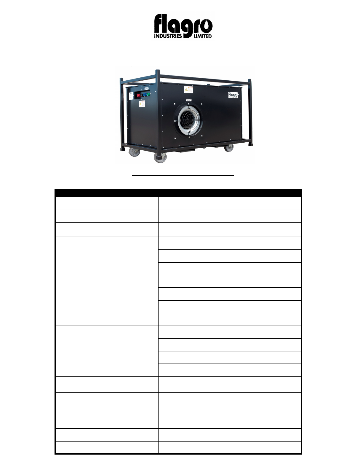
HEATER SPECIFICATIONS
MODEL FLE150
Power Requirements
MAXIMUM INPUT (KW)
BLOWER
TEMPERATURE RISE
AMP DRAW
DB (noise level)
(above ambient)
480V
512,000 btu
7 1/2 H.P.
60KW 67 F
90KW 101 F
150 KW 138 F
MOTOR 7 AMPS
60KW 64 AMPS
90KW 97 AMPS
150KW 161 AMPS
FAN ONLY 85
60KW 73
90KW 76
150KW 79
INLET SIZE
OUTLET SIZE
(Designed for 20" Dia. Ducting)
DIMENSIONS
H X L X W (IN.)
WEIGHT
AIR CIRCULATION
16" Dia.
20" Dia.
40 X 58 X 33
560 LBS
6800 CFM
Page 8
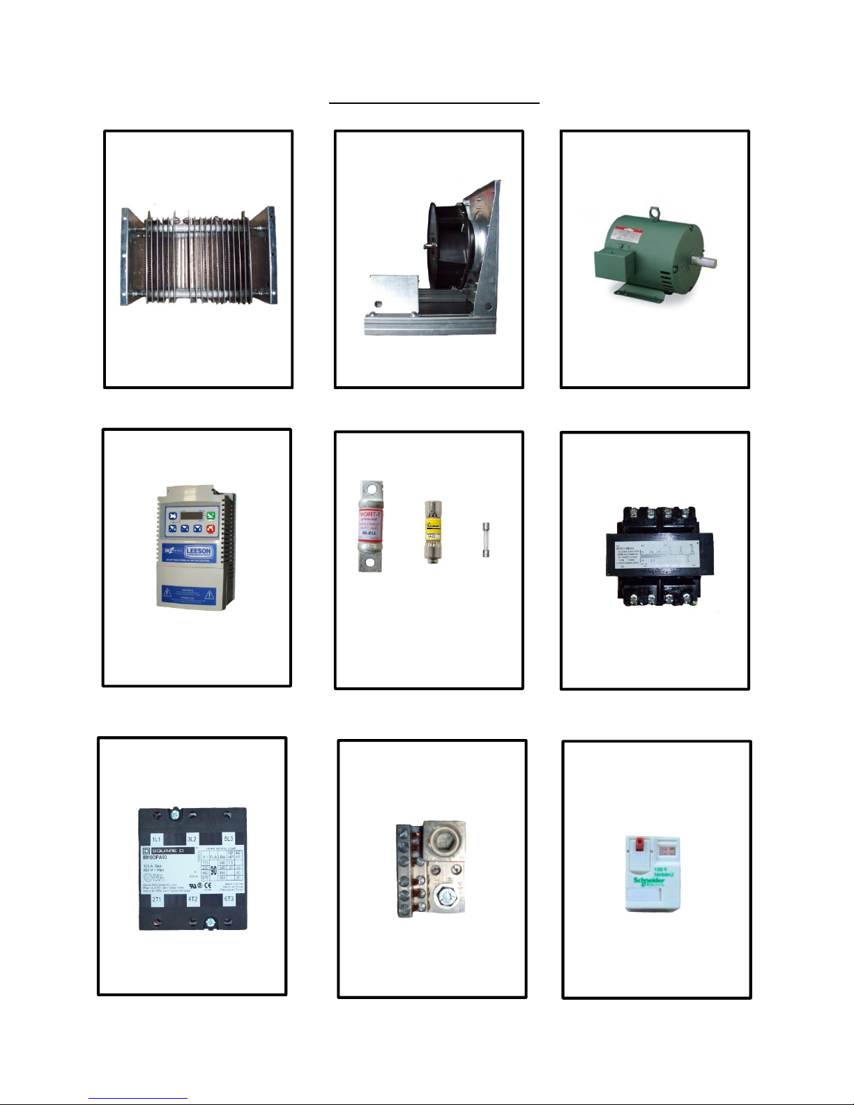
FLE-150– PARTS LIST
150KW RESISTOR ELEMENT
FLE-1501 (480 VOLT)
FLE-1501A (575 VOLT)
VARIALBLE SPEED DRIVE
FAN BLADE ASSEMBLY
FLE-1502
FUSES
7.5 HP MOTOR
FLE- 1503 (480 VOLT)
FLE- 1503A (575VOLT)
TRANSFORMER
FLE-1504 (480 VOLT)
FLE-1504A (575 VOLT)
CONTACTOR
FLE-1507 – 90 amp
(2 PER UNIT)
FLE-1509 - 125 Amp Class T
FLE-1510 - 90 Amp Class T
FLE-1511 – 10 Amp Class CC
FLE-631 – ½ Amp Class CC
FLE-632 - 5 Amp AGC Glass
GROUNDING BLOCK
FLE-621
FLE-627 – 480V
FLE-627A – 575V
RELAY
FLE-626
(2 PER UNIT)
Page 9
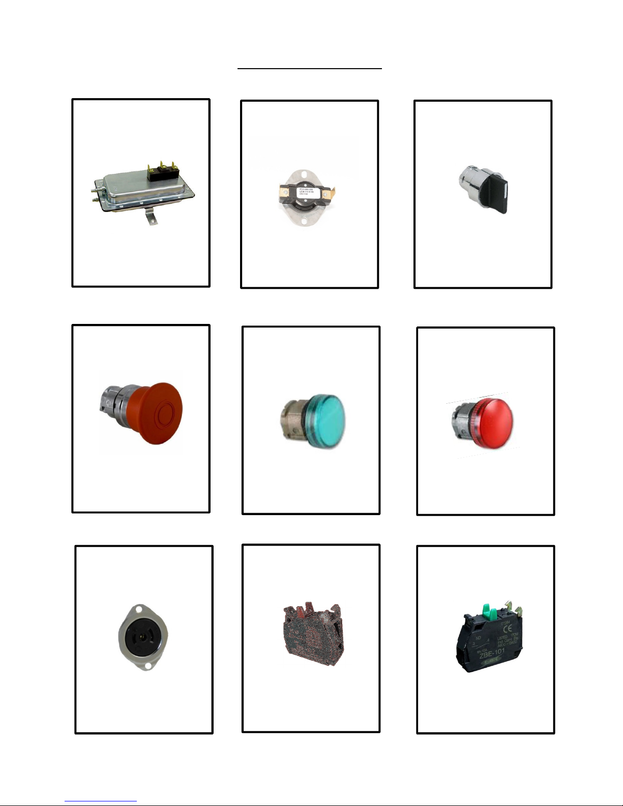
FLE-150 PARTS LIST
AIR PROVING SWITCH
FLE-1512
EMERGENCY STOP BUTTON
HIGH LIMIT
(250-F)
FLE-1513
GREEN AIR PROVEN LIGHT
2 POSITION SWITCH
FLE-633
60KW
90KW
THERMOSTAT/MANUAL
BLOWER ON/OFF
HIGH LIMIT/AIR PROVEN LIGHT
FLE-634
THERMOSTAT
FV-414B
FLE-636
N/C CONTACT BLOCK
FLE-639
(3 PER UNIT)
FLE-635
N/O CONTACT BLOCK
FLE-640
(7 PER UNIT)
Page 10
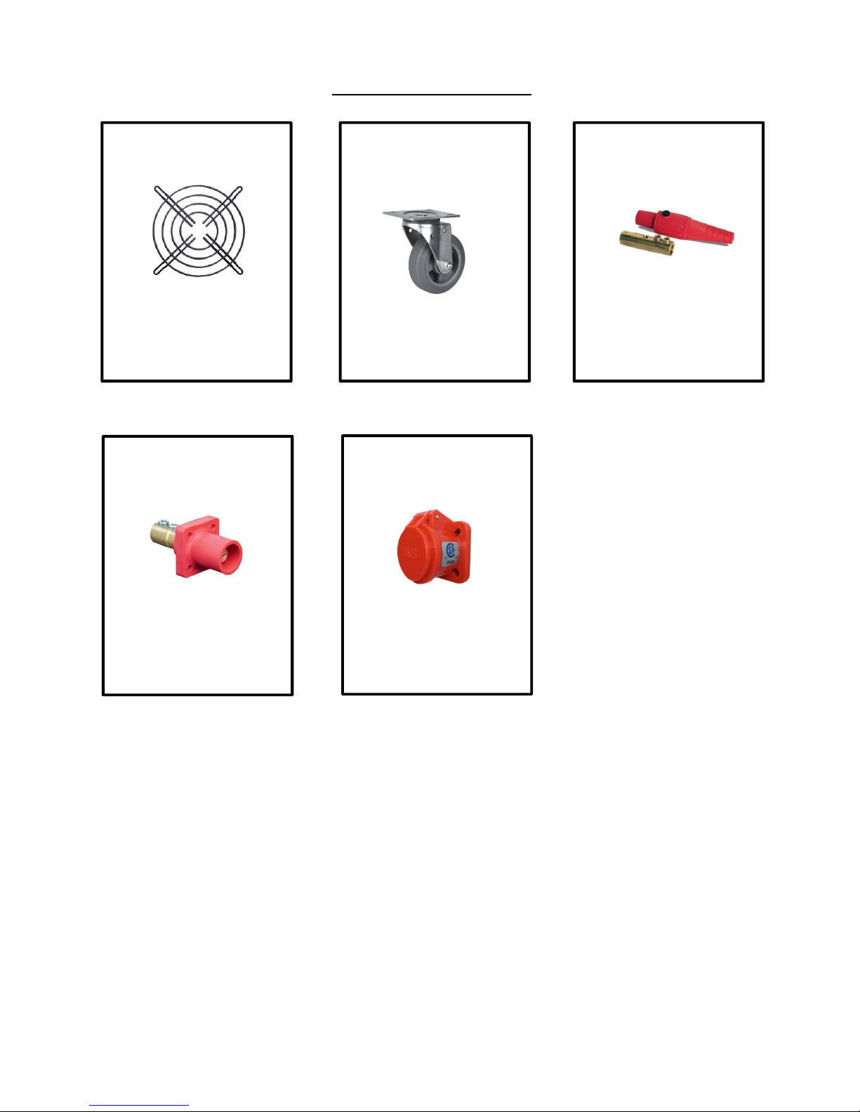
FLE-150 PARTS LIST
INLET GUARD
FLE-1514
CAM-LOCK - PANEL
WHEELS
FLE-609 – 6” LOCKABLE
FLE-610 – 6” RIGID
SNAP COVERS - PANEL
CAM-LOCK DETACHABLE
FLE-615 – BLUE
FLE-616 – BLACK
FLE-617 – GREEN
FLE-618 - RED
FLE-611 – BLUE
FLE-612 – BLACK
FLE-613 – GREEN
FLE-614 - RED
FLE-611A – BLUE
FLE-612A – BLACK
FLE-613A – GREEN
FLE-614A - RED
Page 11

BODY PANELS
P/N DESCRIPTION
FLE-150FR OUTER FRAME
FLE-157 RIGHT SIDE PANEL
FLE-158 LEFT SIDE PANEL
FLE-159 REAR PANEL
FLE-160 FRONT PANEL
FLE-162 TOP PANEL
FLE-162B TOP PANEL ACCESS DOOR
FLE-170 CONTROL PANEL RAIN GUARD
Page 12
PARTS LIST FOR FLE-150
Part Number Part Description
FLE-1501 150KW RESISTOR ELEMENT (480 VOLT)
FLE-1502 FAN BLADE ASSEMBLY
FLE-1503 7.5 HP MOTOR (480 VOLT)
FLE-1504 VARIABLE SPEED DRIVE (480 VOLT)
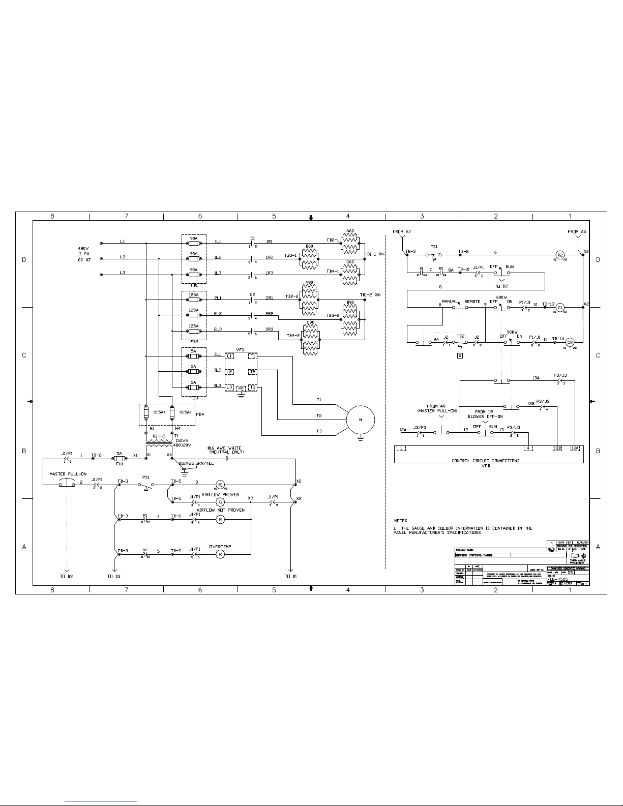
FLE-1505 WIRED CONTROL/OPERATOR PANELS (480 VOLT)
FLE-1507 90 AMP 3P CONTACTOR (TW O PER HEATER)
FLE-1508 480 VOLT TRANSFORMER
FLE-1509 125 AMP CLASS T FUSE (THREE PER HEATER)
FLE-1510 90 AMP CLASS T FUSE (THREE PER HEATER)
FLE-1511 10 AMP CLASS CC TIME DELAY FUSE (THREE PER HEATER)
FLE-1512 AIR PROVING SWITCH COMPLETE
FLE-1513 OUTLET HIGH LIMIT - 250 F
FLE-1514 INLET GUARD
FLE-609 6" LOCKABLE SWIVEL CASTER
FLE-610 6" RIGID CASTER
FLE-611 BLUE MALE PANEL CAM-LOCK
FLE-611A BLUE SNAP COVER
FLE-612 BLACK MALE PANEL CAM-LOCK
FLE-612A BLACK SNAP COVER
FLE-613 GREEN MALE PANEL CAM-LOCK
FLE-613A GREEN SNAP COVER
FLE-614 RED MALE PANEL CAM-LOCK
FLE-614A RED SNAP COVER
FLE-615 BLUE FEMALE DETACHABLE CAM-LOCK
FLE-616 BLACK FEMALE DETACHABLE CAM-LOCK
FLE-617 GREEN FEMALE DETACHABLE CAM-LOCK
FLE-618 RED FEMALE DETACHABLE CAM-LOCK
FLE-621 GROUNDING BLOCK
FLE-622 DISTRIBUTION BLOCK
FLE-626 DAYTON CUBE RELAY (TWO REQUIRED)
Page 13
FLE-631 1/2 AMP CLASS CC TIME DELAY (TWO REQUIRED)
FLE-632 5 AMP AGC GLASS FUSE
FLE-633 TWO POSITION SWITCH
FLE-634 EMERGENCY STOP BUTTON
FLE-635 RED HIGH LIMIT/NON PROVEN AIR LIGHT (TWO PER HEATER)
FLE-636 GREEN AIR PROVEN LIGHT
FLE-637 BULBS FOR FLE-635/FLE-636
FLE-638 OPERATOR BLOCK FOR FLE-635/FLE-636
FLE-639 N/C CONTACT BLOCK (THREE PER HEATER)
FLE-640 N/O CONTACT BLOCK (SEVEN PER HEATER)
Page 14
TROUBLE SHOOTING
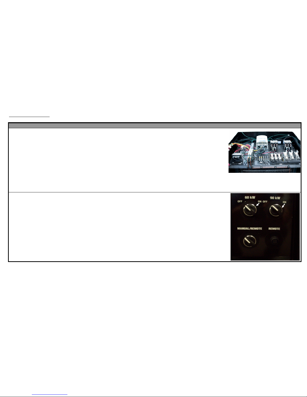
PROBLEM PROBABLE CAUSE REMEDY PARTS
Heater will not start No power to unit Make sure Master pull button is in the out
Controller display does not position.
illuminate Check voltage at main power supply and circuit
breaker.
Blown fuse(s) Check control panel fuses, replace if
necessary.
Main circuit breaker tripped Reset main circuit breaker.
FUSES
Blower runs, no heat kW setting is in the off position(s) Move kW swtich to apppropiate kW setting
Thermostat option not selected properly Check thermostat setting position
If in the remote position, thermostat may not Check thermostat plug to make sure it is
be plugged in properly Plugged in securely
Remote thermostat set too low Adjust thermostat control
Sail switch out of adjustment or defective Check for air flow obstruction. Check belt
tension.
Replace sail switch if required
Defective controller Check controller and replace if needed
Page 15
 Loading...