

Page 1

OPERATING INSTRUCTIONS MANUAL
(Please retain for future reference)
For
F-400T DUAL FUEL CONSTRUCTION HEATER
CERTIFIED FOR USE IN CANADA AND U.S.A.
CSA 2.14 2000 Gas Fired Construction Heaters Unvented /Unattended Type.
As per Standard ANSI Z83.7 2000/
14501 Judicial Road, Suite 40
Burnsville, MN 55306
1-866-266-2484
www.flagrousa.com
Page 2
GENERAL HAZARD WARNING:
FAILURE TO COMPLY WITH THE PRECAUTIONS AND INSTRUCTIONS PROVIDED
WITH THIS HEATER, CAN RESULT IN DEATH, SERIOUS BODILY INJURY AND
PROPERTY LOSS OR DAMAGE FROM HAZARDS OF FIRE, EXPLOSION, BURN,
ASPHYXIATION, CARBON MONOXIDE POISONING, AND/OR ELECTRICAL
SHOCK.
ONLY PERSONS WHO CAN UNDERSTAND AND FOLLOW THE INSTRUCTIONS
SHOULD USE OR SERVICE THIS HEATER.
IF YOU NEED ASSISTANCE OR HEATER INFORMATION SUCH AS AN
INSTRUCTIONS MANUAL, LABELS, ETC. CONTACT THE MANUFACTURER.
WARNING:
FIRE, BURN, INHALATION, AND EXPLOSION HAZARD. KEEP SOLID
COMBUSTIBLES, SUCH AS BUILDING MATERIALS, PAPER OR CARDBOARD, A
SAFE DISTANCE AWAY FROM THE HEATER AS RECOMMENDED BY THE
INSTRUCTIONS. NEVER USE THE HEATER IN SPACES WHICH DO OR MAY
CONTAIN VOLATILE OR AIRBORNE COMBUSTIBLES, OR PRODUCTS SUCH AS
GASOLINE, SOLVENTS, PAINT THINNER, DUST PARTICLES OR UNKNOWN
CHEMICALS.
WARNING:
NOT FOR HOME OR RECREATIONAL VEHICLE USE.
WARNING:
INTENDED USE IS PRIMARILY THE TEMPORARY HEATING OF BUILDINGS
UNDER CONSTRUCTION, ALTERATION, REPAIR OR EMERGENCIES ONLY.
ALWAYS PROVIDE ADEQUATE VENTILATION. 1 SQ. IN. OF FRESH AIR MUST
BE SUPPLIED FOR EVERY 1000 BTUH OF HEAT.
THIS HEATER SHALL BE INSTALLED SUCH THAT IT IS NOT DIRECTLY
EXPOSED TO WATER SPRAY, RAIN AND/OR DRIPPING WATER.
- 2 -
Page 3

This heater is designed and approved for use as a
construction heater under ANSI Z83.7 2000 and
CSA 2.14 2000 Gas Fired Construction Heaters
We cannot anticipate every use which may be made
of our heaters. CHECK WITH YOU LOCAL FIRE
SAFETY AUTHORITY IF YOU HAVE QUESTIONS
ABOUT APPLICATIONS.
Other standards govern the use of fuel gases and heat
producing products in specific applications. Your local
authority can advise you about these.
SPECIFICATIONS
Model ……………………………………………………. F-400T
Input ……………………………………………………... 400,000 btuh
Fuel ……………………………………………………….. Natural Gas or Propane
Inlet Pressure …………………………………………….. Natural Gas: 3.5”W.C.
…………………………………………………
…... Propane: 11” W.C.
Ignition …………………………………………………….. Direct Spark Ignition
.…………………………………………...….. Thermostat Control
Air Circulation …………………………………………….. 2000 cfm
Fuel Consumption ……………………………………...... 18.5 lbs/hr
……………………………………………... 380 cfh
Approved ………………………………………………...... cULus listed
- 3 -
Page 4

INSTALLATION:
The installation of this heater for use with natural gas shall conform with local codes or,
in the absence of codes, with the National Fuel Gas Code ANSI Z223.1/NFPA 54 and
the Natural Gas and Propane Installation Code, CSA B149.1.
The installation of this heater for use with propane tank or cylinder shall conform with
Local codes or, in the absence of local codes, with the Standard for the Storage and
Handling of Liquefied Petroleum Gases, ANSI/NFPA 58 and the Natural Gas and
Propane Installation Code, CSA B149.
This heater must be located at least 10ft (3m) from any propane gas cylinder. This
heater shall not be directed toward any propane gas container within 20ft (6m).
CLEARANCE TO COMBUSTIBLES:
F-400T TOP – 5 ft FRONT – 8 ft SIDES – 2 ft REAR – 1 ft
CONNECTING THE CYLINDER:
If cylinders are used to supply the heater, no cylinders smaller than 100lb capacity shall
be used. These cylinders must supply a vapor withdrawal only.
1. All cylinder connections must be made using a wrench to tighten the POL fitting.
2. Be sure that the cylinder valve is in the closed position when connection
or disconnecting the cylinder.
3. A soap and water solution must be applied to all connections in order to leak
check the system.
The gas must be turned off at the propane supply cylinder(s) when the heater is not in
use. When the heater is to be stored indoors, the connection between the propane
supply cylinder(s) and the heater must be disconnected and the cylinders removed from
the heater and stored in accordance with Standard for the Storage and Handling or
Liquefied Petroleum Gases, ANSI/NFPA 58 and CSA B149.1, Natural Gas and Propane
Installation Code.
PIPING: This heater must be installed by a qualified gas technician following
local codes published by the authority having jurisdiction. Sizing of
supply piping must be determined using the length of pipe run as
well as total btuh rating of the appliance(s). Appropriate piping
tables must be used to determine size of supply piping dependant
on the length of run from source.
- 4 -
Page 5

PRESSURES: MAXIMUM INLET PRESSURES: LP: 14.0 IN. WC.
NG: 14.0 IN. WC.
MINIMUM INLET PRESSURES: LP: 11.0 IN. WC.
NG: 3.5 IN. WC.
This heater must be supplied by pressures indicated on the
approval label. Over pressure may cause controls to fail.
DO NOT supply this unit with more than ½ psig (14.0 in. W.C.)
Note: A second stage regulator must be installed if the supply
pressure exceeds ½ psig.
FUEL: This heater will operate on propane or natural gas. The manifold
pressures are listed on the approval label. Ensure that the proper
pressure settings are achieved depending on the fuel being used.
A fuel selector valve is located on the manifold of the heater.
Ensure that this valve is in the proper position depending on the
fuel being used. DO NOT operate the heater with the valve in the
incorrect position.
HOSES: All hoses used to connect this heater of fuel supply must be Type 1
approved propane / natural gas hose assemblies.
ELECTRICAL: WARNING
Electrical Grounding Instructions
This appliance is equipped with a three-prong (grounding) plug for
your protection against shock hazard and should be plugged
directly into a properly grounded three-prong receptacle.
120v supply must be available. Please note that the motor on this
unit requires 20 amps. Ensure appropriate gauge extension cord is
used.
- 5 -
Page 6

MAINTENANCE:
1. Every construction heater should be inspected before each use, and at least
annually by a qualified service person.
2. The hose assembly shall be visually inspected prior to each use of the heater. If it is
evident there is excessive abrasion or wear, or the hose is cut, it must be replaced
prior to the heater being put into operation. The replacement hose assembly shall be
that specified by the manufacturer.
3. The appliance must be kept clear and free from combustible materials, gasoline and
other flammable vapors and liquids.
4. The flow of combustion and ventilation air must not be obstructed. Be sure to check
the fan assembly and ensure that the motor and blade are operating properly.
5. Compressed air should be used to keep components free of dust and dirt build up.
Note: Do not use the compressed air inside any piping or regulator components.
- 6 -
Page 7
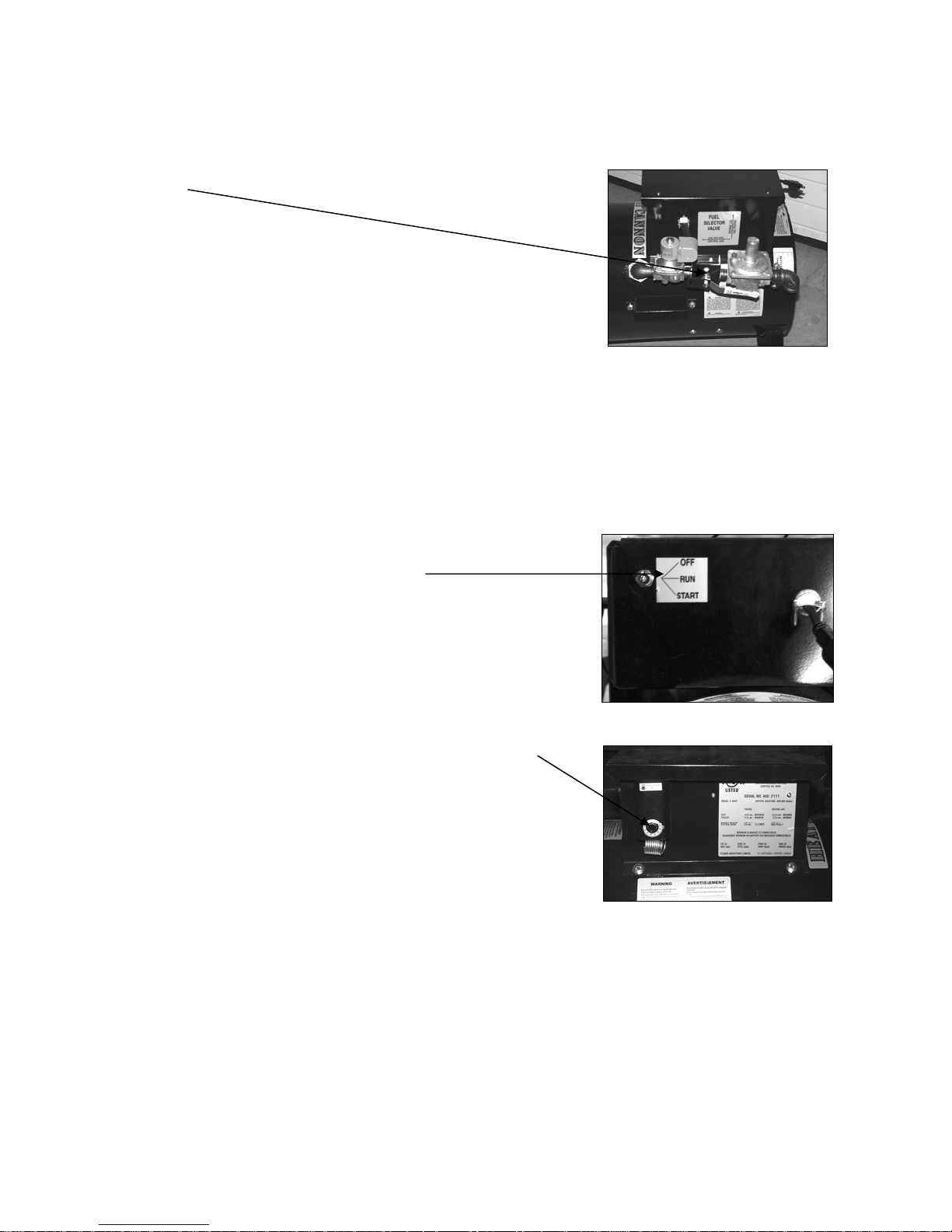
START UP INSTRUCTIONS:
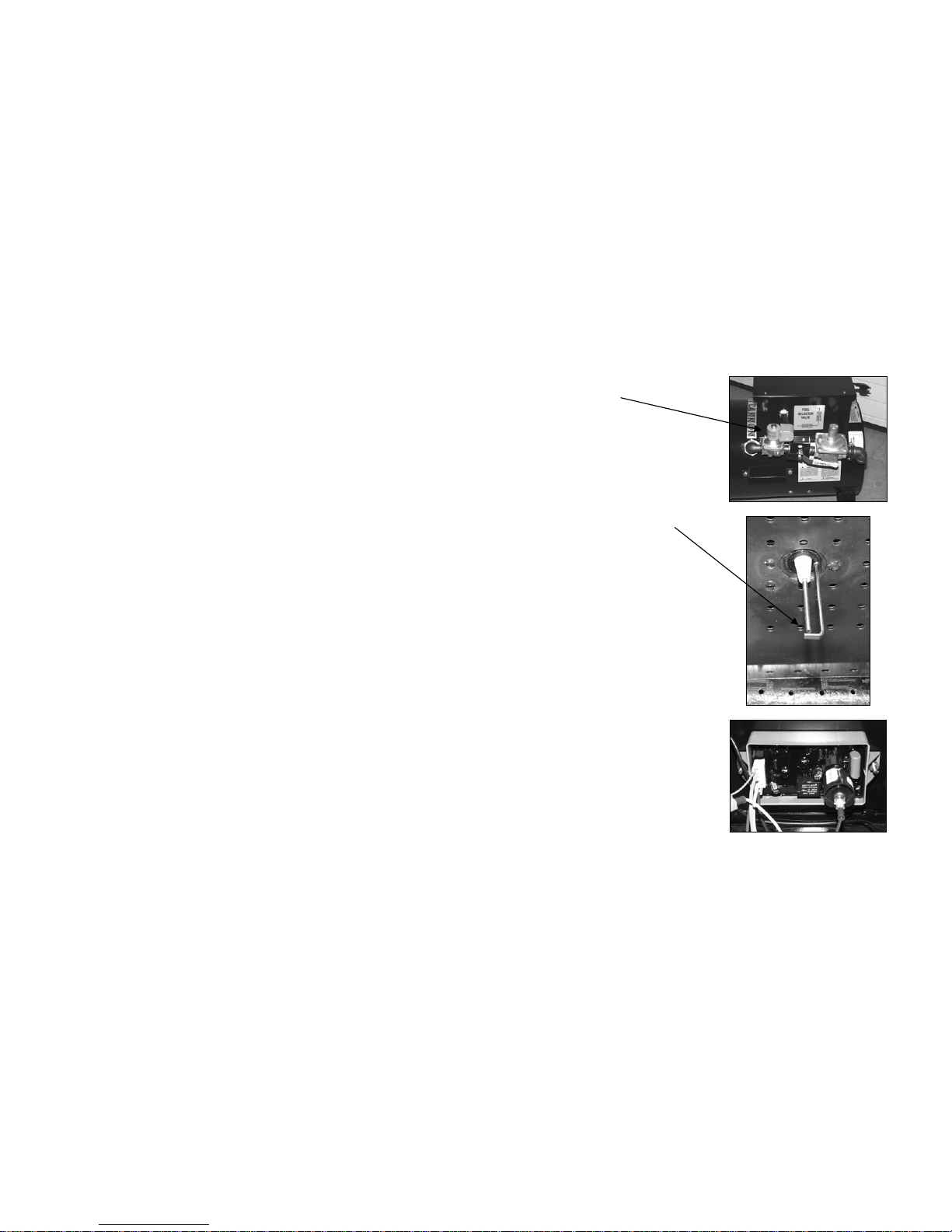
1. Set fuel selector valve according to gas supply to be
used.
2. Connect construction heater to gas supply with
approved hose assembly.
3. Plug the electrical cord into a grounded electric
supply.
4. Open all gas supply valves.
5. Depress the main switch to the “START” position.
The fan motor will start and the burner should ignite.
Release switch to “RUN” position.
6. Set the Thermostat to the desired temperature.
7. If heater fails to ignite after 3 attempts call your
supplier for service.
- 7 -
Page 8
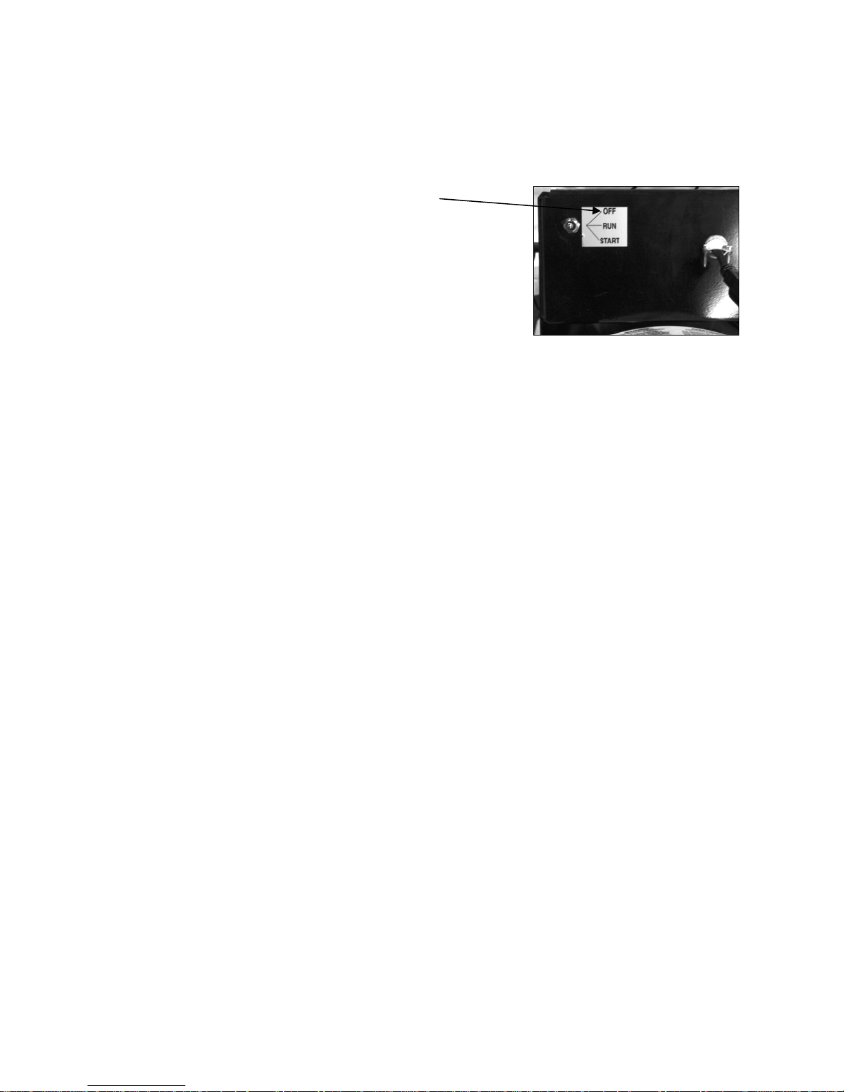
TO SHUT DOWN:
1. Close main gas supply valve while heater is
operating.
2. Move main switch to the “OFF” position.
3. Disconnect heater from gas supply.
- 8 -
Page 9
- 9 -
F-400T TROUBLESHOOTING ANALYSIS
PROBLEM POSSIBLE CAUSES REMEDY
Heater will not light
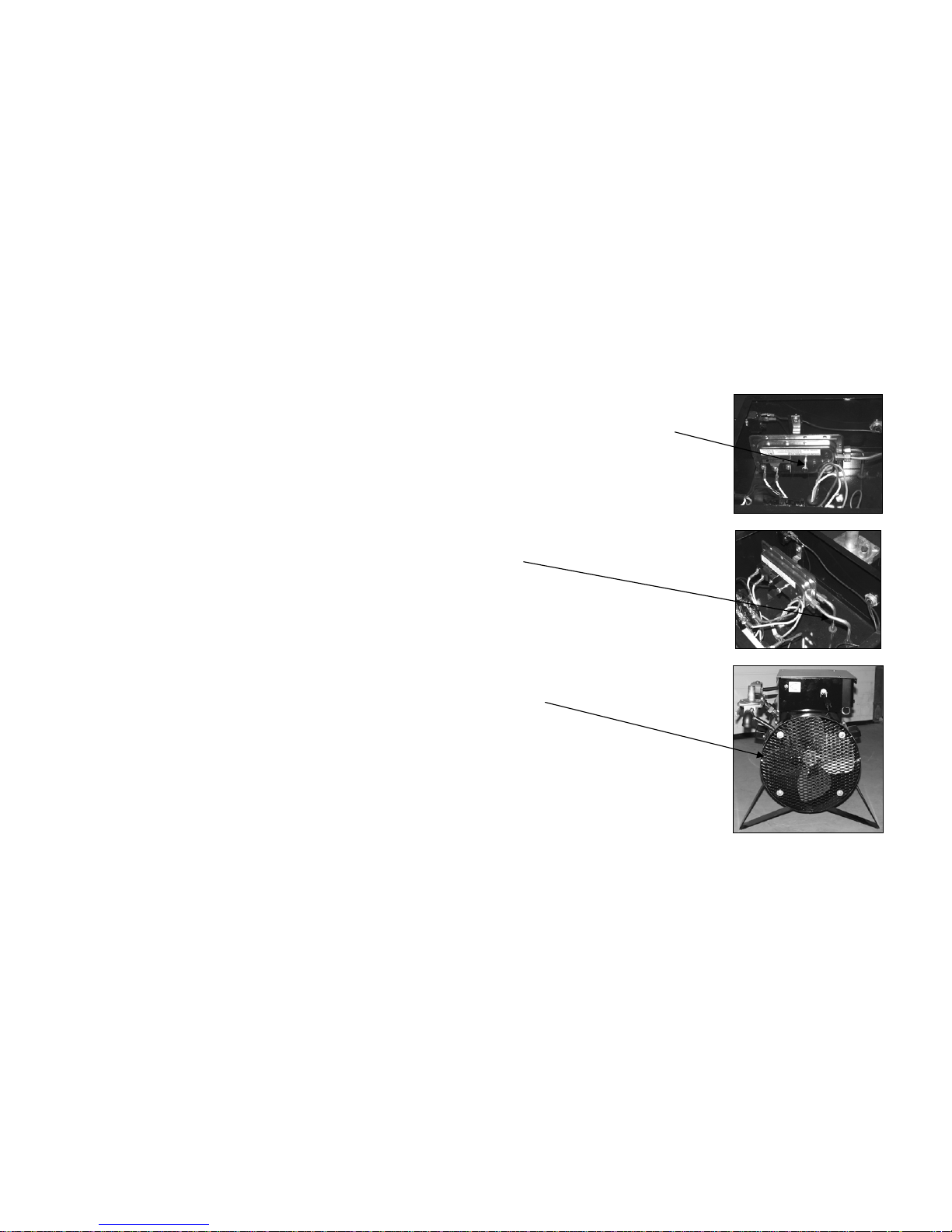
Air switch improperly set
- use centre adjusting screw to set air switch.
Turn clockwise to increase sensitivity, turn
counter clockwise to decrease sensitivity.
Blockage in copper inlet
tubes
- disconnect tubes from switch. Use high
pressure air to clean any debris that may
block airflow.
Rear of heater blocked - ensure rear of heater is unobstructed and
proper rear clearances are maintained (see
approval label)
Faulty switch - replace switch
Page 10
- 10 -
Gas supply - ensure required gas supply pressures are
supplied to the heater (see approval label)
Solenoid - ensure solenoid is energized (use volt
meter)
- ensure plunger in solenoid is being
activated (use manometer at test point after
solenoid)
Spark Plug - ensure gap in spark plug is approx. 1/8”
- check spark plug wire connections
- ensure spark plug has good spark
- replace spark plug if necessary
Ignition Board - ensure electrical signals for both spark plug
and solenoid are present (use volt meter)
- ensure ignition board is properly grounded
Page 11
- 11 -
Thermostat - ensure thermostat is calling for heat
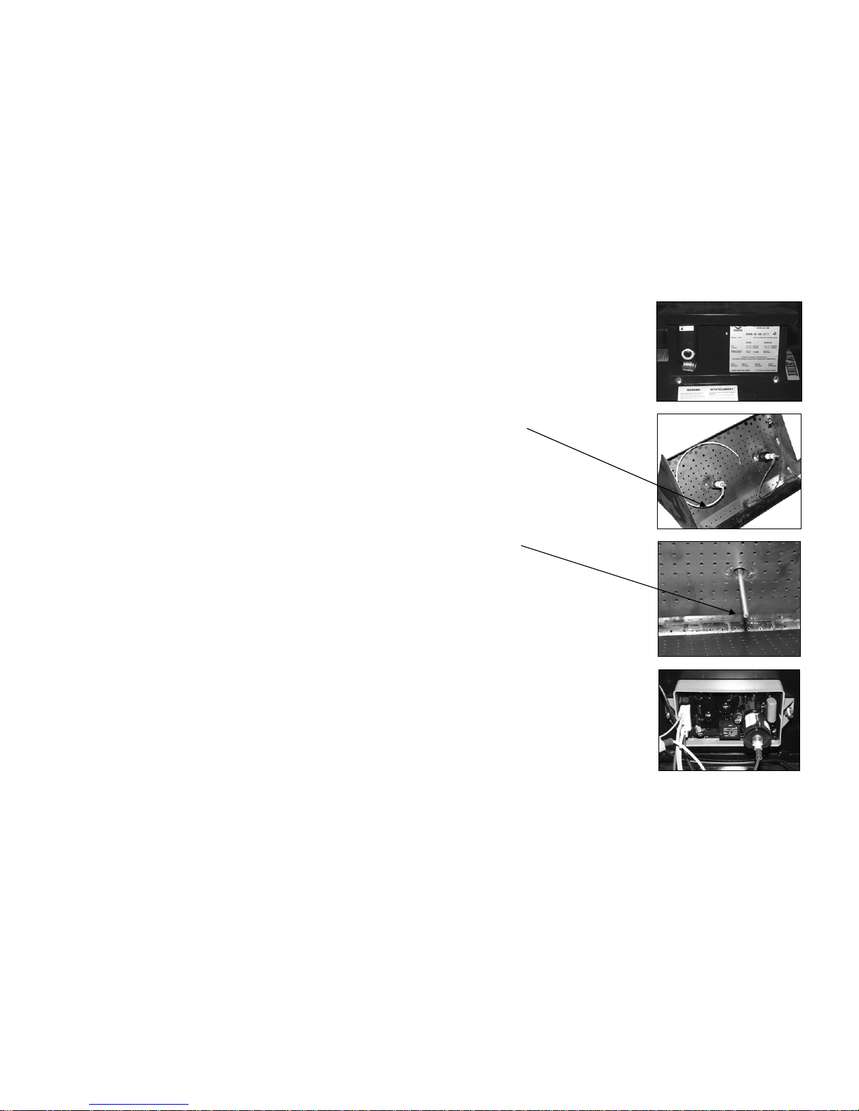
Heater will not remain lit after start up Faulty flamerod wire - check flamerod wire for any damage.
Replace if necessary.
Faulty flamerod -ensure connections are secure. Replace
flamerod if necessary.
Ignition board - check ground wire for proper connection
- check polarity of extension cord compared
to polarity of plug on the heater
- replace faulty ignition board
Thermostat - ensure thermostat is calling for heat
Page 12
- 12 -
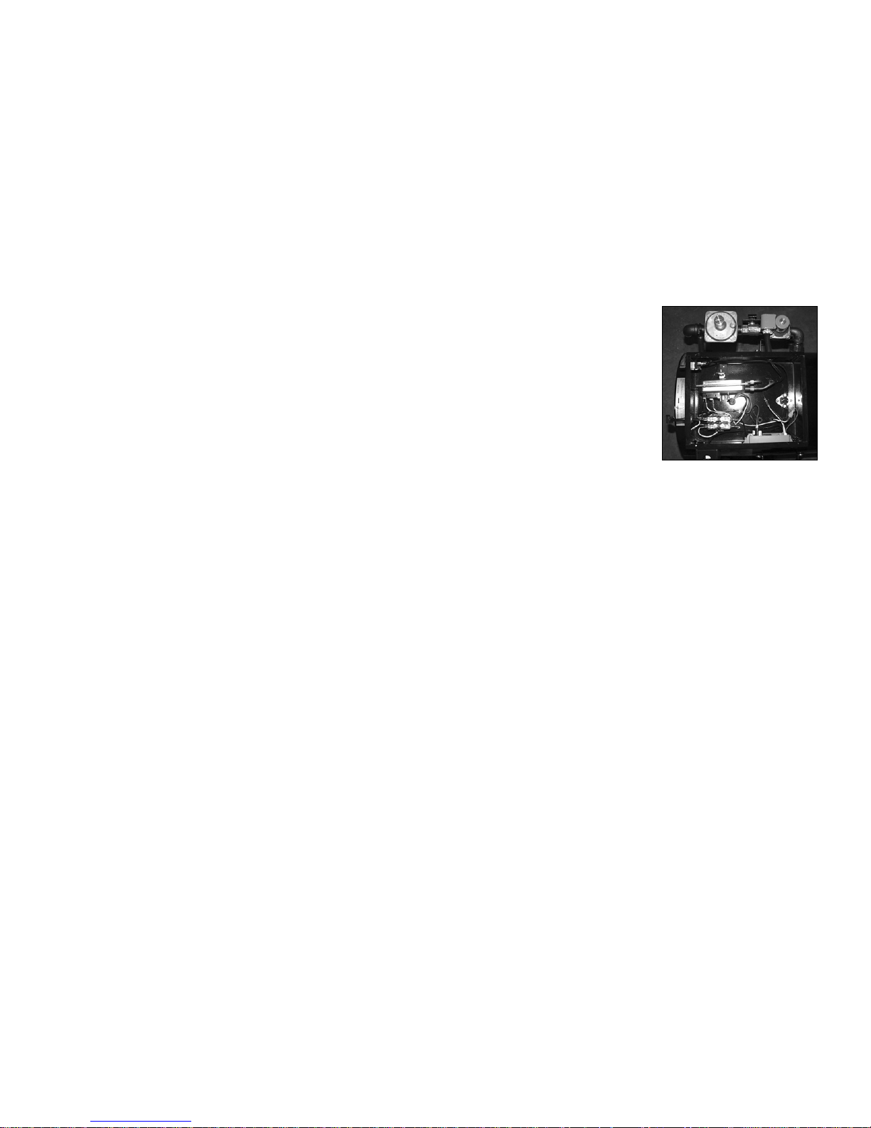
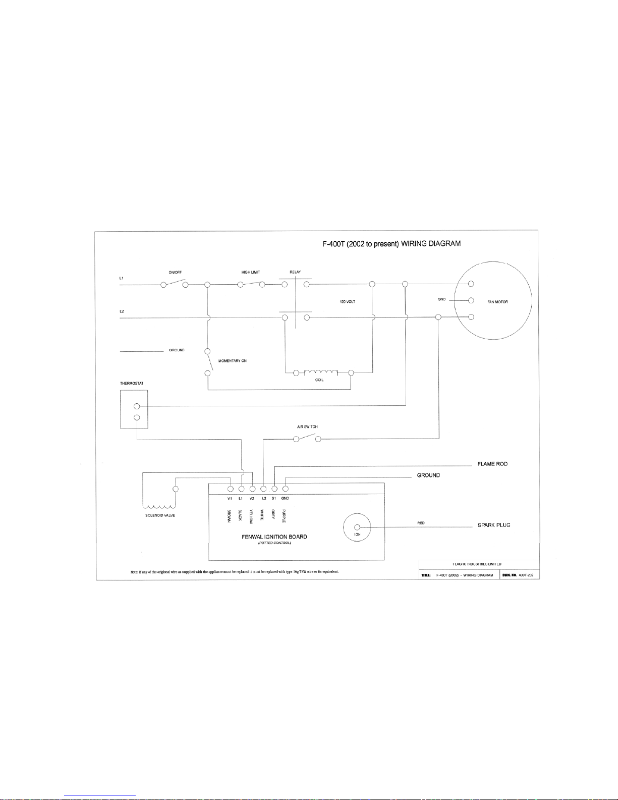
Electrical All components - before replacing any component, all
connections must be checked to ensure
electrical circuit is complete. (Use volt meter
and enclosed wiring diagram).
- any point in the circuit where 120v is not
achieved indicates location of problem
and/or possible faulty component.
Piping All pipe fittings - When loosened, tightened or replaced, the
complete fitting should be removed and
approved pipe dope applied to all male
threads before reconnection.
- After a heater is serviced, the valve train
should be checked for leaks with a soap and
water solution or approved leak detector
solution.
Page 13
- 13 -
 Loading...