

FläktGroup MULTIMAXX HG Series, MULTIMAXX HG 24, MULTIMAXX HG 25, MULTIMAXX HG 45, MULTIMAXX HG 44 Operation Manual
®
MULTIMAXX
OPERATION MANUAL
HG
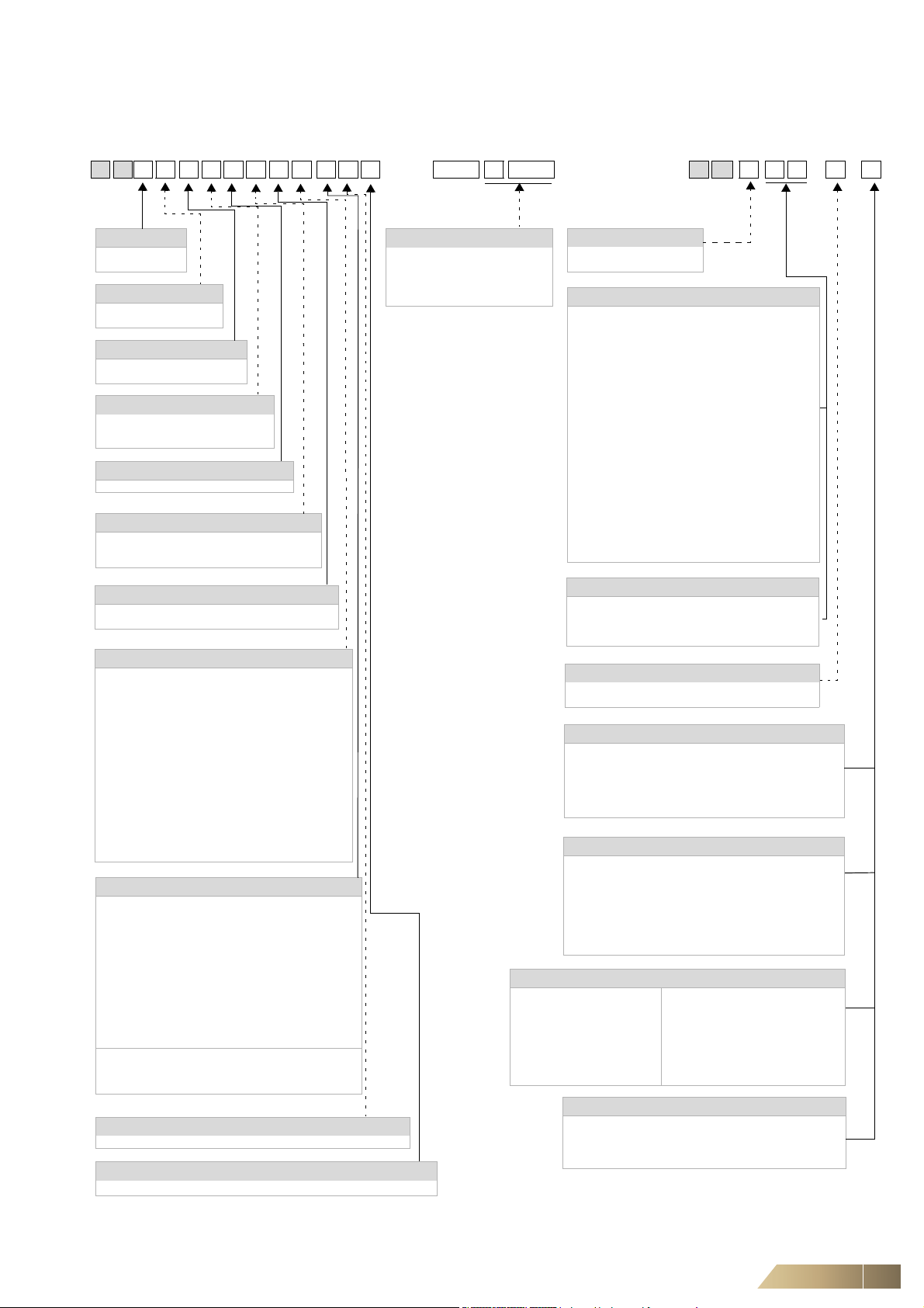
MultiMAXX HG Unit Type Code
H G 2 4 . U E F T C B . A M D OSHG 0 . 000M Z HX.XX X X
Model size
2 = Model size 2
4 = Model size 4
Capacity stage
4 = Low capacity
5 = High capacity
Unit configuration
U = Recirculating-air operation
M = Mixed air unit
Heating medium
E = Natural gas (EG),
propane-butane (LPG)
Heat exchanger
F=
High-temperature resistant steel
Regulation of heating capacity
P = Regulation of supply air temperature
(only with mixed-air units)
T = Regulation of room temperature
Unit configuration
B = Non-room-sealed firing
C = Room-sealed firing
Outlet
A = Outlet nozzle ceili ng
B = Basis - wall
C = Secondary-air louvre, ceiling, manually adjustable
D = Motorized secondary-air louvre, ceiling, (230 V,
open/close)
K = Blank flange, pressure side
L = Air deflection louvre
P = Profile outlet
T = Gate nozzle
U = Secondary-air louvre, wall installation,
manual adjustment
V = Four sides, ceiling
W = Motorized secondary-air louvre, wall, (230 V, open/
close)
Z = Two-side basic ceiling outlet
O = Without louvre
Air side accessories
20 = Mixed-air module, type 1
21 = Mixed-air module, type 2
23 = Outside air blocking damper
25 = Flexible canvas connector
26 = Rectangular duct 150
27 = Rectangular duct 1000
28 = Duct bend 90°, symmetrical
29 = Duct bend 90°, asymmetrical
31 = Wall air-intake hood
32 = External weather grille
33 = Contact protection grille
34 = Roof duct, slanted roof
35 = Roof air intake hood
(38 = spare filter for roof air intake hood)
36 = Bag filter module
(39 = spare filter for the bag filter module)
37 = Mat filter module
(40 = spare filter for mat filter module)
49 = Roof duct with flat roof-duct base
51 = Frame for wall connection
52 = Flange (for recirculating-air units)
Ohne Auslass
Motor / speeds
AC Motor
A = 3x400V, 2-speed - low speed range, wide-blade fan,
for capacity stage (4)
B = 3x400V, 2-speed - high speed range, wide-blade fan,
for capacity stage (5)
D=
1x230V, 2-speed - low speed range, wide-blade fan,
for lower capacity stage (4) (only for BG2)
E = 1x230V, 2-speed - high speed range, wide-blade fan,
for capacity stage (5)
Q = 3x400V, 2-speed - low speed range, sickle-blade fan,
for capacity stage (4)
R = 3x400V, 2-speed - high speed range, sickle-blade fan,
for capacity stage (5)
(only for BG4)
EC Motor
Y = 1x230V, continuous, sickle-blade fan
Z = 3x400V, continuous, sickle-blade fan
(only for BG4)
Electric equipment
M = Control system Multi (steel sheet box)
Unit casing
D = Heat exchanger in industrial design RAL 7000
Model size
2 = Model size 2
4 = Model size 4
Configuration / material
0 = Standard config uration
8 = Ecodesign
(only for ZH#.25, 26, 35, 36, 38, 39 )
Actuators for louvers and mixed-air modules
0 = Actuator on site
1 = Manual
2 = Actuator 230 V, open/close
3 = Actuator 230 V, Open/Close + Poti
4 = Actuator 230 V, Open/Close + final position switch
5 = Actuator 230 V+ spring return
Filter class / electric equipment
0 = Without filter, without differential pressure switch
2 = G2/without differential pressure switch
3=
G3 / without differential pressure switch (only for ZH#.37)
4 = G4/without differential pressure switch
5 = G2/with differential pressure switch
6=
G3 / with differential pressure switch (only for ZH#.37)
7 = G4/with differential pressure switch
9 = G7/with differential pressure switch
(only for ZH#.35, 36)
Suspensions
53 = Compact C
54 = Studio (for wall configuration)
55 = Modular (for wall configuration)
56 = Ceiling suspension
Modular (
ZH#.
550#) with accessories
0 = without accessories 7 = 25+23+51
1 = 25+20+51 8 = 25+36+23+51
2 = 25+36+20+51 9 = 25+37+23+51
3 = 25+37+20+51 A = 26+36
4 = 25+21+29+51 B = 26+37
5 = 25+36+21+29+51 C = 25+28 (+49...)
6 = 25+37+21+29+51 W = without unit accessories
with vertical outlet
Suspension ceiling (
ZH#.
560#)
0 = Without threaded rod
1 = Threaded rod 1 m
2 = Threaded rod 2 m
3 = Threaded rod 3 m
Control panel, Control board
0.000M = Control panel Multi
(AC Motor)
0.EC0M = Control panel Multi
(EC Motor)
0.RDDO = Control board RDDO
Unit Type Code
MultiMAXX Control Accessories
FläktGroup DC-2011-0141-GB 2018-05/R5 • Subject to modifications 3

Table of Contents MultiMAXX HG
Unit Type Code . . . . . . . . . . . . . . . . . . . . . . . . . . . . . . . . . . . . . . . .3
1 Safety and User Instructions. . . . . . . . . . . . . . . . . . . . . . . . . . . . .6
1.1 Scope of the operation manual . . . . . . . . . . . . . . . . . . . . . . . . . . . . . . . . . . 6
1.2 Symbols used . . . . . . . . . . . . . . . . . . . . . . . . . . . . . . . . . . . . . . . . . . . . . . . 6
1.3 Safety-conscious work procedures . . . . . . . . . . . . . . . . . . . . . . . . . . . . . . . 7
1.4 Proper use . . . . . . . . . . . . . . . . . . . . . . . . . . . . . . . . . . . . . . . . . . . . . . . . . 8
1.5 Safety regulations and codes . . . . . . . . . . . . . . . . . . . . . . . . . . . . . . . . . . . 8
1.6 Modifications and changes . . . . . . . . . . . . . . . . . . . . . . . . . . . . . . . . . . . . . 8
1.7 Spare parts . . . . . . . . . . . . . . . . . . . . . . . . . . . . . . . . . . . . . . . . . . . . . . . . . 8
1.8 Personnel selection and qualification . . . . . . . . . . . . . . . . . . . . . . . . . . . . . 8
2 Specifications . . . . . . . . . . . . . . . . . . . . . . . . . . . . . . . . . . . . . . . . .9
2.1 Unit configuration and packaged content . . . . . . . . . . . . . . . . . . . . . . . . . . 9
2.2 Specification of material . . . . . . . . . . . . . . . . . . . . . . . . . . . . . . . . . . . . . . 10
2.3 Functional description of the unit . . . . . . . . . . . . . . . . . . . . . . . . . . . . . . . 11
2.4 Operating conditions . . . . . . . . . . . . . . . . . . . . . . . . . . . . . . . . . . . . . . . . . 11
2.5 Unit dimensions and minimum mounting space . . . . . . . . . . . . . . . . . . . . 12
2.6 Specifications . . . . . . . . . . . . . . . . . . . . . . . . . . . . . . . . . . . . . . . . . . . . . . 13
2.7 Specification for the Ecodesign Directive passed by the EU Commission
2016/2281 14
3 Shipping and Storage. . . . . . . . . . . . . . . . . . . . . . . . . . . . . . . . . .17
3.1 Shipping . . . . . . . . . . . . . . . . . . . . . . . . . . . . . . . . . . . . . . . . . . . . . . . . . . 17
3.2 Shipping and handling of the unit . . . . . . . . . . . . . . . . . . . . . . . . . . . . . . . 17
3.3 Storage . . . . . . . . . . . . . . . . . . . . . . . . . . . . . . . . . . . . . . . . . . . . . . . . . . . 18
4 Mounting . . . . . . . . . . . . . . . . . . . . . . . . . . . . . . . . . . . . . . . . . . . .19
4.1 Load-bearing capacity of the installation site . . . . . . . . . . . . . . . . . . . . . . 19
4.2 Ceiling mounting . . . . . . . . . . . . . . . . . . . . . . . . . . . . . . . . . . . . . . . . . . . . 19
4.3 Wall mounting . . . . . . . . . . . . . . . . . . . . . . . . . . . . . . . . . . . . . . . . . . . . . . 20
4.4 Safety clearance . . . . . . . . . . . . . . . . . . . . . . . . . . . . . . . . . . . . . . . . . . . . 22
4.5 Unit mounting . . . . . . . . . . . . . . . . . . . . . . . . . . . . . . . . . . . . . . . . . . . . . . 22
4.6 Installing the flue gas pipework . . . . . . . . . . . . . . . . . . . . . . . . . . . . . . . . . 22
4.7 Mounting examples . . . . . . . . . . . . . . . . . . . . . . . . . . . . . . . . . . . . . . . . . . 23
5 Electrical Connection. . . . . . . . . . . . . . . . . . . . . . . . . . . . . . . . . .25
5.1 Electrical control box . . . . . . . . . . . . . . . . . . . . . . . . . . . . . . . . . . . . . . . . . 26
5.2 Connection diagrams . . . . . . . . . . . . . . . . . . . . . . . . . . . . . . . . . . . . . . . . 26
5.3 Multi operation . . . . . . . . . . . . . . . . . . . . . . . . . . . . . . . . . . . . . . . . . . . . . 26
5.4 Connection actuator, mixed-air module, and blocking damper . . . . . . . . . 31
5.5 Connecting actuator for secondary-air louvre D and W . . . . . . . . . . . . . . 31
5.6 Connection for differential pressure switch . . . . . . . . . . . . . . . . . . . . . . . . 31
6 Gas Connection . . . . . . . . . . . . . . . . . . . . . . . . . . . . . . . . . . . . . .32
6.1 Gas distribution . . . . . . . . . . . . . . . . . . . . . . . . . . . . . . . . . . . . . . . . . . . . . 32
7 Commissioning. . . . . . . . . . . . . . . . . . . . . . . . . . . . . . . . . . . . . . .33
7.1 Initial commissioning - information for service companies . . . . . . . . . . . . 33
4 FläktGroup DC-2011-0141-GB 2018-05/R5 • Subject to modifications

MultiMAXX HG Table of Contents
8 Operation . . . . . . . . . . . . . . . . . . . . . . . . . . . . . . . . . . . . . . . . . . . 44
8.1 General Operation . . . . . . . . . . . . . . . . . . . . . . . . . . . . . . . . . . . . . . . . . . .44
8.2 Operation and adjustment of the units by means of the control panel
OSHG 0.000M (OSHG 0.EC0M) . . . . . . . . . . . . . . . . . . . . . . . . . . . . . . . .44
8.3 Adjustment of the mixed-air module . . . . . . . . . . . . . . . . . . . . . . . . . . . . .54
8.4 Adjustment of the secondary-air louvre . . . . . . . . . . . . . . . . . . . . . . . . . . .54
8.5 Differential pressure switch . . . . . . . . . . . . . . . . . . . . . . . . . . . . . . . . . . . .54
8.6 Decommissioning . . . . . . . . . . . . . . . . . . . . . . . . . . . . . . . . . . . . . . . . . . .54
9 Maintenance. . . . . . . . . . . . . . . . . . . . . . . . . . . . . . . . . . . . . . . . . 55
9.1 Maintenance . . . . . . . . . . . . . . . . . . . . . . . . . . . . . . . . . . . . . . . . . . . . . . .55
9.2 Quarterly maintenance . . . . . . . . . . . . . . . . . . . . . . . . . . . . . . . . . . . . . . .56
9.3 Semi-annual maintenance . . . . . . . . . . . . . . . . . . . . . . . . . . . . . . . . . . . . .57
9.4 Break-downs . . . . . . . . . . . . . . . . . . . . . . . . . . . . . . . . . . . . . . . . . . . . . . .58
10 Disassembly and Disposal . . . . . . . . . . . . . . . . . . . . . . . . . . . . . 59
10.1 Disassembly . . . . . . . . . . . . . . . . . . . . . . . . . . . . . . . . . . . . . . . . . . . . . . .59
10.2 Recycling . . . . . . . . . . . . . . . . . . . . . . . . . . . . . . . . . . . . . . . . . . . . . . . . . .59
11 Warranty Conditions . . . . . . . . . . . . . . . . . . . . . . . . . . . . . . . . . . 60
11.1 Authorized service companies for warranty and repairs in Germany . . . .60
11.2 Warranty certificate . . . . . . . . . . . . . . . . . . . . . . . . . . . . . . . . . . . . . . . . . .61
EC DECLARATION OF CONFORMTI . . . . . . . . . . . . . . . . . . . . . 63
Original operation manual – Copyright note
Disclosing, copying, distributing or taking any action in reliance on the contents of this document is strictly prohibited without
express prior consent. Violations entail liability for any damages or other liability arising. All rights in relation to patents, utility
patents or design patents are reserved.
FläktGroup DC-2011-0141-GB 2018-05/R5 • Subject to modifications 5
Safety and User Instructions MultiMAXX HG
1 Safety and User Instructions
This is an original operation manual verified by the manufacturer.
MultiMAXX HG Air Heaters are developed and manufactured according to the current
state of technology and the recognized safety-specific standards and guidelines and
correspond to the EU Directive of Machinery.
MultiMAXX HG Air heaters are safe to operate and comply with high quality standards.
Future-oriented technology and pronounced operator and maintenance friendliness
were combined in this product series.
However, every unit heater can pose an unavoidable residual danger for the user or
third parties, or can lead to impairments of the unit or other objects. For this reason, it
is important to observe the safety regulations without fail. The unit and its maintenance
must be carried out according to all prevailing regulations and standards.
Failure to follow the safety precautions could result in death, serious injury, environmental damage and/or considerable property damage.
Observing the safety instructions in the current operation manual will help avoid the
risks, ensure economical operation of the unit and let you enjoy the full benefits of the
product.
The safety aspects covered by this chapter are valid for the entire operation manual.
1.1 Scope of the operation manual
This operation manual provides critical information about the following:
–Shipping
– Mounting
– Installation
– Electrical connection
– Commissioning
–Operation
– Maintenance, cleaning and disposal
1.2 Symbols used
In these operating instructions, the following symbols are used for special text
passages:
– Indicates text paragraphs
• Indicates process instructions
Indicates process results.
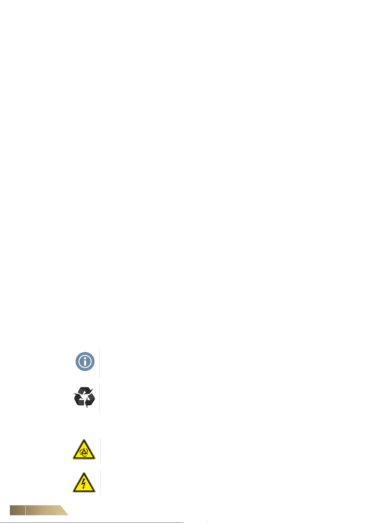
NOTE!
You will find supplementary information on the use of the
MultiMAXX HG Unit Heater and its economical handling
RECYCLING!
This symbol is used to highlight instructions on proper reuse of packaging material
and disused assembly groups (separated according to recyclable materials).
The following names and symbols are employed in the operating instructions for the
safety notices:
WARNING: RISK OF ROTATING COMPONENTS!
This section specifies procedures and precautions for preventing personal injury
resulting from rotating unit components.
HAZARDOUS VOLTAGE!
This symbol indicates a risk of accident due to electric shock.
6 FläktGroup DC-2011-0141-GB 2018-05/R5 • Subject to modifications
MultiMAXX HG Safety and User Instructions
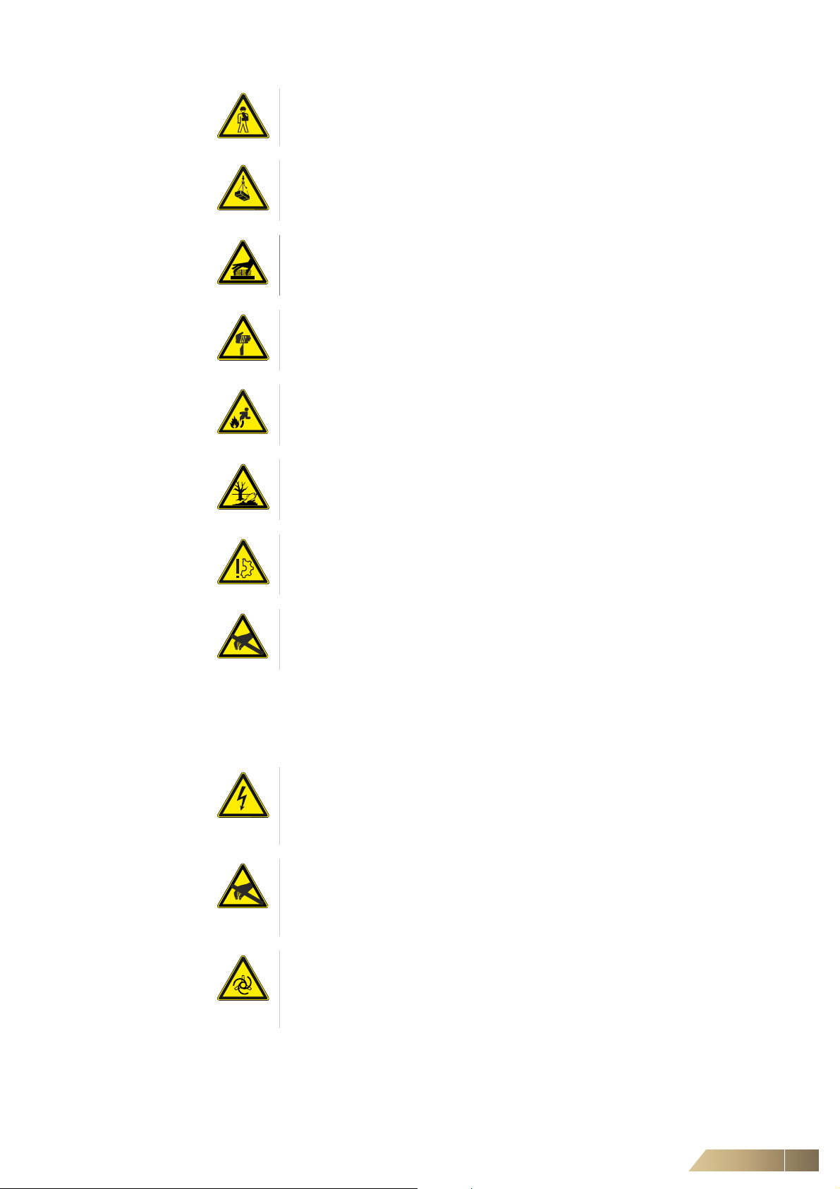
PERSONAL INJURY!
This section specifies procedures and precautions for preventing personal injury.
DANGER DUE TO OVERHEAD LOADS!
This symbol warns about personal injury and damage caused by overhead loads and
suspended heavy objects.
DANGER OF HOT SURFACES!
This section specifies procedures and precautions for preventing personal injury
resulting from contact with hot surfaces.
DANGER – SHARP CUTTING EDGES!
This section specifies procedures and precautions for preventing personal injury
resulting from cuts on thin metal fins.
RISK OF ACCIDENTS BY GAS EXPLOSION!
This section specifies particular information and prohibitions for avoiding personal
injury through gas explosions.
ENVIRONMENTAL DAMAGE!
This symbol warns about damage to the environment or refers to all existing national
environmental protection regulations.
EQUIPMENT DAMAGE!
This section specifies information and precautions for avoiding damages to the
MultiMAXX HG Unit Heater.
RISK OF DAMAGE DUE TO STATIC DISCHARGE!
This symbol precedes a warning of risks of damage to unit electronic components
due to static discharge.
1.3 Safety-conscious work procedures
Observe the following instructions during installation, configuratoin, repair and maintenance tasks:
HAZARDOUS VOLTAGE!
Disconnect all electric power to the unit and ensure the power cannot be inadvertently switched on, earth, short-circuit, and block off all neighboring live parts. Noncompliance can lead to death or serious injury.
RISK OF DAMAGE DUE TO STATIC DISCHARGE!
When doing connection and/or adjustment work on the MultiMAXX HG unit heater,
make sure that you statically discharge yourself before touching printed circuit
boards and electrical components.
WARNING: RISK OF ROTATING COMPONENTS!
Danger of injury from turning fan wheel Before performing any work on the unit,
ensure that the unit is isolated. Ensure that the unit is isolated and secured against
being energised at an appropriate point of the on-site power supply.
Fluctuations or deviations of the supply voltage may not exceed the tolerance limits
specified in the technical data on the unit identification plate, otherwise function failures
and limit states cannot be excluded.
FläktGroup DC-2011-0141-GB 2018-05/R5 • Subject to modifications 7
Safety and User Instructions MultiMAXX HG
1.4 Proper use
The MultiMAXX HG unit heaters are used in industrial, warehouse, sales and exhibition
rooms, i.e. in areas which are protected against the influences of weather (including
assembly, temporary storage, and maintenance work). They serve for heating, ventilation and filtering of the room-/outside air.
The unit must be used according to Commission Regulation (EU) No 1253/2014.
In all areas which demand a room air-independent firing, the units are equipped with a
fresh-air supply (coaxial flue gas pipework can be optionally employed).
In all areas where there is the danger of negative pressure, it is absolutely necessary
to use units with a room air-independent configuration.
Filters, mixed-air and air intake modules, suspension sets, control units and control
devices can be supplied as optional accessories.
Proper use also stipulates the observance of the current operation manual as well as
adherence to all inspection and maintenance intervals specified by FläktGroup.
Improper use Any use other than that described above is considered improper.
The manufacturer/supplier is not liable for any damages arising from improper use.
The user alone bears the risk.
PERSONAL INJURY!
The MultiMAXX Air Heaters may not be operated:
– in explosion risk areas
– in rooms with high dust or moisture content
– in rooms with strong electromagnetic fields
– in rooms with aggressive atmosphere
1.5 Safety regulations and codes
For the assembly of the electrical connection and gas connection, commissioning,
repair and maintenance work of MultiMAXX equipment, observe the respective safety
regulations and standards which are valid in the respective countries and generally
recognized rules of technology.
1.6 Modifications and changes
Do not attempt to modify, add components, or convert the MultiMAXX unit heater in any
way.
Changes or modifications of the unit heater will invalidate the CE conformity and render
all warranty claims as null and void.
1.7 Spare parts
Only original FläktGroup spare parts are allowed, since FläktGroup is not liable for
damages if third-party-spare parts are used.
1.8 Personnel selection and qualification
NOTE!
Every person who works on the MultiMAXX Unit Heater must have completely read
and understood this entire operating manual.
Assembly/maintenance/repair may only be carried out by trained workers observing
the valid regulations and standards.
The commissioning may only be carried out by specialists briefed in the prevailing
standards and regulations and who have installed the complete unit.
The electrical installation may only be carried out by skilled electricians observing
the valid regulations.
The gas installation may only be carried out by trained gas specialists observing
the valid regulations.
All skilled staff must be able to assess the entrusted work and must be able to recognize and avoid all associated dangers.
8 FläktGroup DC-2011-0141-GB 2018-05/R5 • Subject to modifications
MultiMAXX HG Specifications
11
10
9
7
8
4
2
1b
125
6
1a
3
2 Specifications
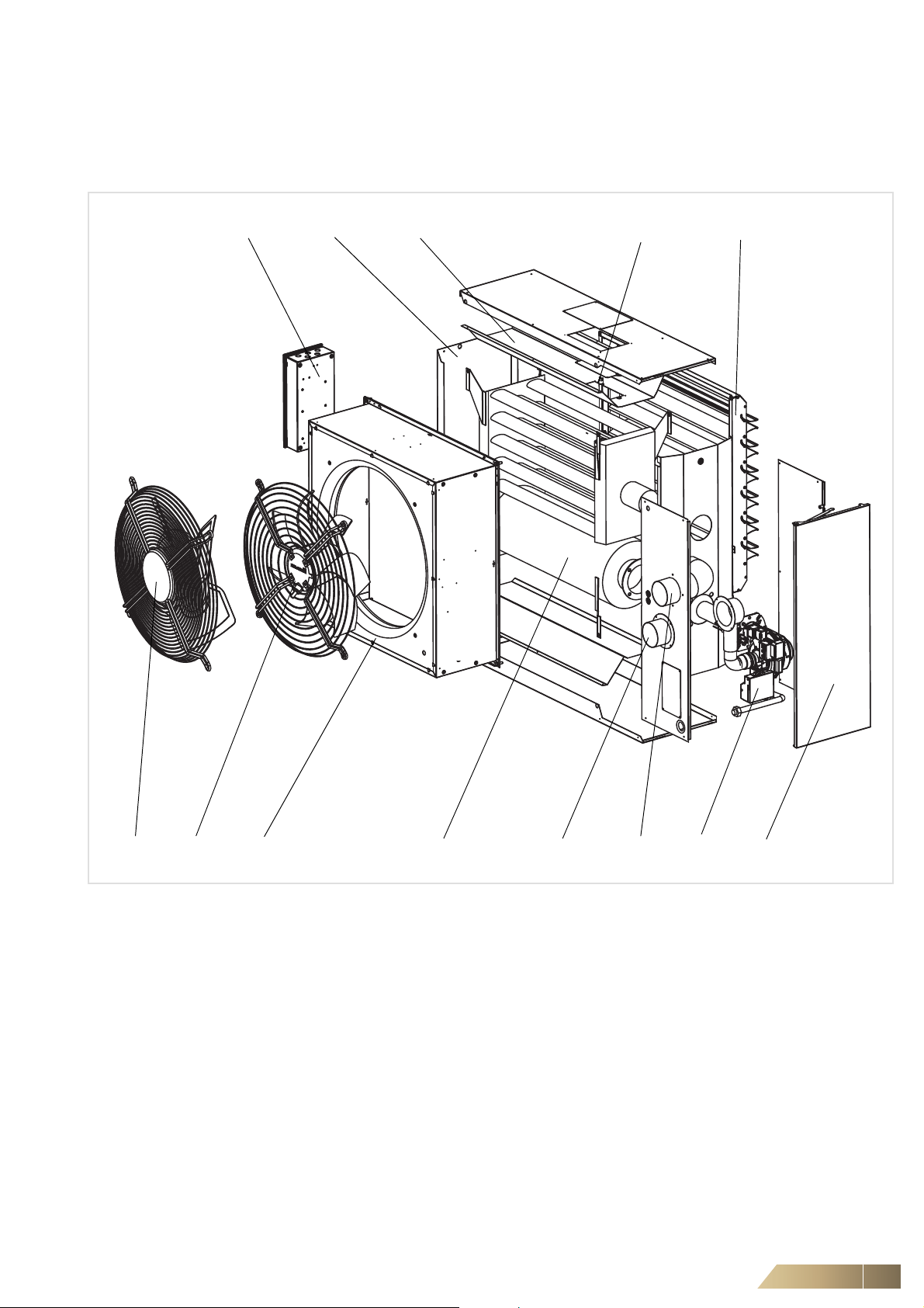
2.1 Unit configuration and packaged content
Fig. 2-1: Technical Description MultiMAXX HG
Pos. 1a: Wide-blade fan (optional)
Pos. 1b: Sickle-blade fan (optional)
Pos. 2: Fan section with air inlet nozzle
Pos. 3: Electrical control box for Multi Operation (metal sheet)
Pos. 4: Heat exchanger
Pos. 5: Heat exchanger casing
Pos. 6: Reflection plates
Pos. 7: Flue pipe fitting of air intake
Pos. 8: Flue gas fitting for smoke exhaust
Pos. 9: Gas burner
Pos. 10: Gas burner casing
Pos. 11: Outlet (optional)
Pos. 11: Thermal fuse
FläktGroup DC-2011-0141-GB 2018-05/R5 • Subject to modifications 9

Specifications MultiMAXX HG
Various unit parts indicated in Fig. 2-1 are specified in detail as follows.
Wide-blade fan (Pos. 1a)
Axial fan with external rotor motor and integrated contact protection grille, aluminum
wide blade, balanced by the manufacturer, maintenance-free with moisture proof
motor wired ready for connection in the terminal box.
Protection class IP 54, heat class F, external thermal contact,
in 2 variants 400 V, 50 Hz and 2 variants 230 V, 50 Hz.
Sickle-blade fan (Pos. 1b)
Axial fan with external rotor AC or EC motor and integrated contact protection grille.
Sickle blade, balanced by the factory, maintenance-free with moisture-proof motor and
wired to the terminal box.
Protection class IP 54, heat class F, external thermal contact,
in 2 variants 400 V, 50Hz.
Fan section with air inlet nozzle (Pos. 2)
The fan section is made of galvanized metal sheet and equipped with 8 x M8 rivet nuts
for the suspension of the unit.
Electrical control box for regulation (Pos. 3)
Steel sheet terminal box contains regulation circuit board with terminal block.
Heat exchanger (Pos. 4)
The heat exchanger is simple and robust, furnished with a combustion chamber and
integrated retractions, thereby ensuring an optimal heat transfer between the combustion chamber and the air to be warmed. The heat exchanger is made of high-temperature resistant steel.
Heat exchanger casing (Pos. 5)
The heat exchanger casing is assembled by the manufacturer and made of galvanized
steel sheet, painted in RAL 7000.
Gas burner (Pos. 9)
The fully automatic gas-pressure burner provides for the temperature rise in the heat
exchanger. The burner can be used for the following gas configurations: natural gas,
gas propane-butane, only propane, and only butane.
Outlet (Pos. 11)
The air outlets direct the warmed air in the desired direction.
2.2 Specification of material
Unit part Material
Fan with contact protection grille Aluminum-metal mix + diverse materials
Fan section Galvanized metal sheet
Electric cabinet made of galvanized steel sheet + diverse materials.
Heat exchanger High-temperature resistant steel
Unit casing made of painted steel sheet RAL 7000
Outlet The frame is made of galvanized painted sheet metal or galvanized steel
sheet. The leaves are made of galvanized steel sheet or aluminum profiles
Gas burner Aluminum-metal mix + diverse materials
Tab. 2-1: Specification of material
10 FläktGroup DC-2011-0141-GB 2018-05/R5 • Subject to modifications
MultiMAXX HG Specifications
2.3 Functional description of the unit
Die gas-unit heaters MultiMAXX HG are produced in 2 model sizes with 2 capacity
sizes each for wall or ceiling mounting. The basis of the unit is formed by a heat
exchanger with a robust combustion chamber and integrated retractions, assuring an
optimal heat transfer between the combustion chamber and the air to be warmed.
The heat exchanger is installed in a thin-walled high temperature-resistant steel casing
(RAL 7000).
The 4 M8 rivet nuts on each side of the fan module are for mounting the unit on the
ceiling or wall.
The back side of the unit is furnished with a 2-speed axial AC or EC fan with integrated
contact protection grille. The thermal contact is guided out and wired to the terminal
box. A flange can be mounted on the fan module of the unit, which permits the connection of air-side accessories.
An air outlet is mounted on the discharge side of the unit, ensuring the regulation of the
air direction and air throw of the warmed air compared to the position of the unit in the
room. The outlet is made of several selectable types (see unit type code on page 3)
The warming of the heat exchanger is ensured by a fully automatic Premix burner. The
burner can process the following gases: natural gas, propane-butane gas, only propane and only butane.
2.4 Operating conditions
Operating temperature 0°C to +40°C
Operating voltage 3 x 400 V, or 1 x 230 V~ 50 Hz
Protection class IP 40 as per EN 60 529
Fan power consumption see unit identification plate
Class of the gas burner: I
I
Class NO
Variant types of the exhaust installation: B
Gas burner input pressure of the heating medium:
Max. power consumption: ca. 150 W (see unit plate)
Operating voltage: 1 x 230 V~ 50Hz
The unit heaters MultiMAXX may only be operated under the conditions (apart from
temperature) described in Chapter 3.3.
For the operation of the MultiMAXX heating units, sufficient air ventilation of the area
must be ensured without fail.
NOTE!
All other important data on dimensions, weights, connections, sound power etc. are
provided in the "Data and Facts about the MultiMAXX HG Unit Heater".
- natural gas (NG)
2R
- propane-butane (PB), propane (P),
3R
butane (B)
: see Tab. 2-2
X
23, C53
, C13, C
23 ,C33
(as per EN 1020)
- natural gas 2 ±0.2 kPa
- propane/butane 3 ±0.3 kPa
Unit type Concentration NO
ppm mg/kWh mg/m
HG 24
HG 25
HG 44
HG 45
Tab. 2-2: Specification of the NOX class
FläktGroup DC-2011-0141-GB 2018-05/R5 • Subject to modifications 11
15 - 22 28 - 40 28 - 41 5
20 - 22 36 - 40 38 - 41 5
25 - 27 45 - 50 47 - 53 5
25 - 40 45 -71 47 - 75 4
X
3
Class NOX
Specifications MultiMAXX HG
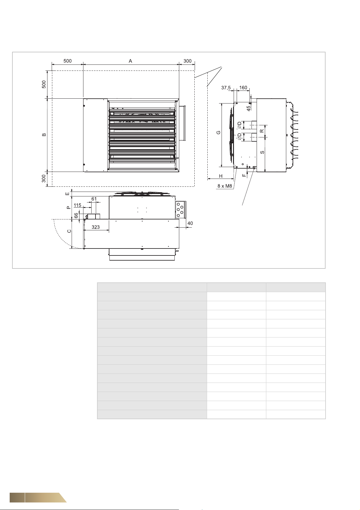
Minimum mounting space
for installation and maintenance
Connection of the unit to the gas mains by
means of accessory article # ZHG.00xx with
internal screw thread R 3/4" (without accessory external screw thread R 1/2"- within the
unit).
2.5 Unit dimensions and minimum mounting space
Fig. 2-2: Unit dimensions MultiMAXX HG
Dimension / BG
A [mm] 918 1206
B [mm] 701 954
C [mm] 340 370
D [mm] 80 100
E (for fan A, B, D, E) [mm] 81 112
E (for fan R) [mm] -66
E (for fan Y) [mm] 65 53
E (for fan Z) [mm] -53
F [mm] 110 75
G [mm] 514 802
H [mm] 300 400
P [mm] 222,5 288
R [mm] 126 195
S [mm] 352 424
Tab. 2-3: Unit dimensions MultiMAXX HG (for Fig. )
2 4
12 FläktGroup DC-2011-0141-GB 2018-05/R5 • Subject to modifications
MultiMAXX HG Specifications
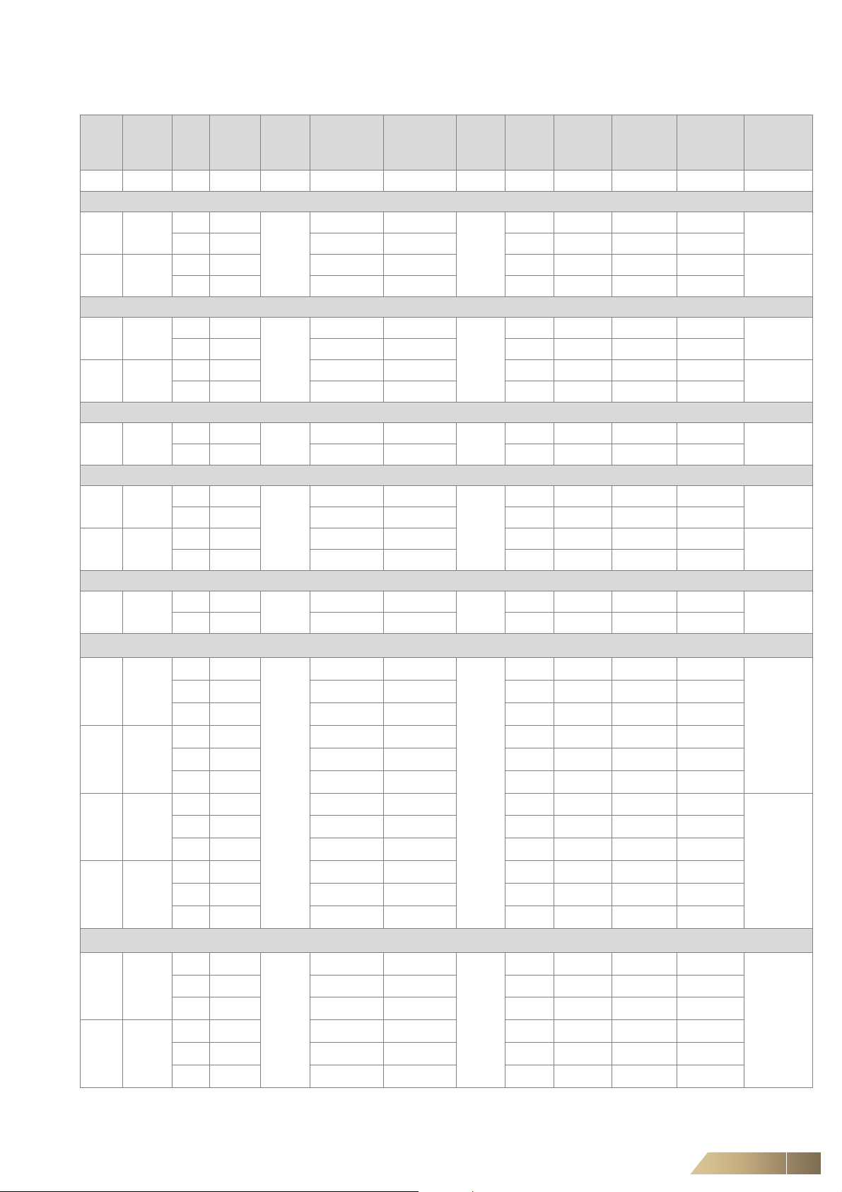
2.6 Specifications
Type
Thermal
output
A - 3 ~ 400 V, AC Motor, 2-speed (low speed range)
HG24 15 ÷ 25
HG44 25 ÷ 45
B - 3 ~ 400 V, AC Motor, 2-speed (high speed range)
HG25 20 ÷ 30
HG45 40 ÷ 60
D - 1~ 230V, AC Motor, 2-speed (low speed range)
HG24 15 ÷ 25
E - 1~ 230V, AC Motor, 2-speed (high speed range)
HG25 20 ÷ 30
HG45 40 ÷ 60
R - 3 ~ 400 V, AC Motor, 2-speed (high speed range)
HG45 40 ÷ 60
Y - 1~ 230V, EC Motor, 3-speed
HG24 15 ÷ 25
HG25 20 ÷ 30
HG44 25 ÷ 45
HG45 40 ÷ 60
Z - 3 ~ 400 V, EC Motor, 3-speed
HG44 25 ÷ 45
HG45 40 ÷ 60
Speed Air flow
range
Q
T
[kW] [min-1][m3/h] [V] [A] [kW] [V] [dB(A)] [m] [m] [m] [kg]
710 2395
910 2825
500 5210 0,78 0,24 64 5,1 6,7 7,9
650 6725 1,11 0,36 70 6,0 7,9 10,2
890 3085
1270 4035
740 8065 2,02 0,63 75 6,8 8,9 12,3
910 9475 2,04 0,78 79 7,6 9,9 14,4
460 1705
890 2790
780 2820
1210 4105
700 8455 3,93 0,67 77 7,0 9,2 12,9
910 9555 3,71 0,83 82 7,6 10,0 14,5
650 8020
870 10425
670 1890
805 2280
945 2665
945 2665
1285 3735
1600 4690
505 5260
590 5955
670 7065
785 8295
925 9840
1050 11005
505 5260
590 5955
670 7065
785 8295
925 9840
1050 11005
rate
V
Fan
voltage
L
3x400
3x400
1x230
1x230
3x400
1x230
3x400
U
Fan max.
power
consumption
I
0,40 0,13
0,57 0,19 66 7,1 9,2 13,5
0,59 0,27
0,83 0,38 74 9,0 11,7 19,3
0,79 0,12
0,89 0,21 66 7,0 9,1 13,3
1,88 0,26
2,04 0,43 74 9,1 11,8 19,6
1,87 0,72
2,72 1,08 79 8,1 10,6 15,8
0,45 0,09
0,51 0,11
0,61 0,13
0,95 0,19
1,12 0,23
1,34 0,29
0,64 0,14
1,03 0,23
1,72 0,39
2,23 0,50
2,92 0,64
3,94 0,89
0,77 0,19
0,88 0,23
1,01 0,29
1,75 0,50
2,18 0,64
2,82 0,89
Fan max.
current
consumption
P
Burner
voltage
U
1x230
1x230
1x230
1x230
1x230
1x230
1x230
Sound
power
Air throw
(louvre B)
63 6,4 8,3 11,4
69 7,5 9,8 14,7
55 5,1 6,6 8,1
66 7,1 9,2 13,5
72 6,8 8,9 12,2
61 5,4 7,0 9,0
64 6,1 8,0 10,9
68 6,8 8,9 12,7
68 6,8 8,9 12,7
76 8,6 11,1 17,8
82 10,0 13,0 22,4
61 5,1 6,7 8,0
65 5,6 7,3 9,1
69 6,2 8,2 10,7
73 7,0 9,1 12,6
77 7,8 10,2 15,0
81 8,4 11,0 16,7
61 5,1 6,7 8,0
65 5,6 7,3 9,1
69 6,2 8,2 10,7
73 7,0 9,1 12,6
77 7,8 10,2 15,0
81 8,4 11,0 16,7
Air throw
(louvre U,
W)
Suspension
(louvre C, D)
height
Weight
with burner
without
louvre
65
112
65
112
65
65
112
112
65
112
112
Tab. 2-4: Technische Beschreibung
FläktGroup DC-2011-0141-GB 2018-05/R5 • Subject to modifications 13
Specifications MultiMAXX HG
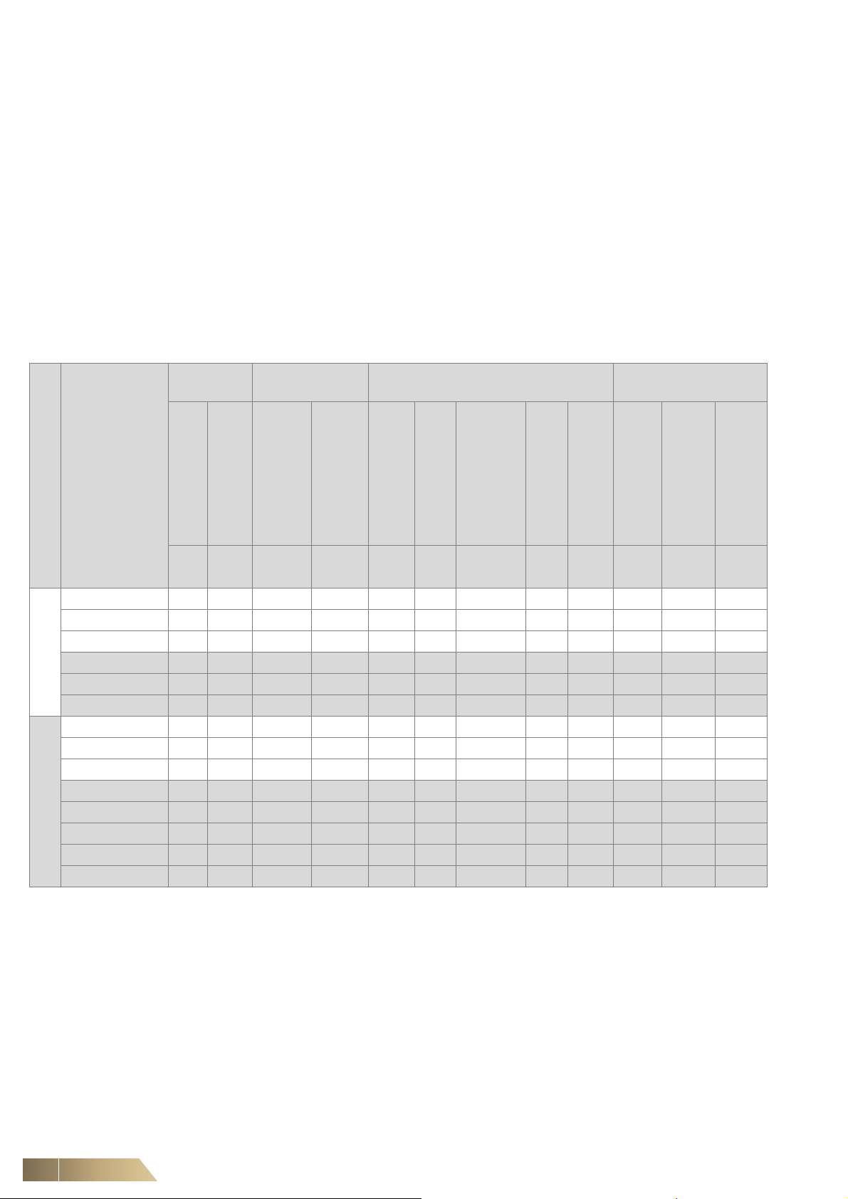
2.7 Specification for the Ecodesign Directive passed by the EU Commission 2016/2281
The values presented in the Tab. 2-5 below are provided to ensure the implementation
of the EU Directive 2016/2281. This Directive sets the framework for the requirements
to the environmentally-friendly design of energy-related products such as air heaters,
air coolers, units for air cooling in industrial processes with high operating temperatureand fan coil units.
Information to identify the models
B1 warm air heater: no
C2 warm air heater: no
C4 warm air heater: no
Type of fuel: gas
Capacity Useful efficiency Other items
nom
Model size
HG24.######.A## 21,7 13,8 87,8 93,2 0,0 0,0 40 94,6 84,5 0,043 0,030 0,008
HG24.######.D## 21,7 13,8 87,8 93,2 0,0 0,0 40 91,9 82,0 0,043 0,030 0,008
HG24.######.Y## 21,7 13,8 87,8 93,2 0,0 0,0 40 92,6 82,7 0,043 0,030 0,008
2
HG25.######.B## 25,6 18,0 86,6 90,5 0,0 0,0 40 94,2 81,3 0,057 0,034 0,008
HG25.######.E## 25,6 18,0 86,6 90,5 0,0 0,0 40 93,7 80,9 0,057 0,034 0,008
HG25.######.Y## 25,6 18,0 86,6 90,5 0,0 0,0 40 93,5 80,7 0,057 0,034 0,008
HG44.######.A## 39,7 20,7 94,6 96,0 0,0 0,0 50 95,9 90,0 0,098 0,055 0,008
HG44.######.Y## 39,7 20,7 94,6 96,0 0,0 0,0 50 95,9 89,9 0,098 0,055 0,008
HG44.######.Z## 39,7 20,7 94,6 96,0 0,0 0,0 50 95,9 89,9 0,098 0,055 0,008
HG45.######.B## 52,7 33,0 91,1 95,2 0,0 0,0 71 95,8 87,9 0,140 0,070 0,008
4
HG45.######.E## 52,7 33,0 91,1 95,2 0,0 0,0 71 96,0 88,0 0,140 0,070 0,008
HG45.######.R## 52,7 33,0 91,1 95,2 0,0 0,0 71 95,8 87,9 0,140 0,070 0,008
HG45.######.Y## 52,7 33,0 91,1 95,2 0,0 0,0 71 96,0 88,1 0,140 0,070 0,008
HG45.######.Z## 52,7 33,0 91,1 95,2 0,0 0,0 71 96,0 88,1 0,140 0,070 0,008
Unit code
rated,h
Rated heating capacity
P
[kW] [kW] [%] [%] [%] [kW]
min
Minimum capacity
P
Useful efficiency at rated
heating capacity ƞ
pl
Useful efficiency at
minimum capacity ƞ
env
Envelope loss factor
F
ign
Ignition burner power
consumption P
Emissions of nitrogen
oxides NOxEmission efficiency ƞ
[mg/kWh
input energy
(GCV)]
s,flow
[%] [%] [kW] [kW] [kW]
s,h
Seasonal space heating
energy efficiency ƞ
Electric power
consumption
elmax
At rated heating capacity
P
Tab. 2-5: Values according to the EU Directive 2016/2281
elmin
At minimal capacity
P
In standby mode
P
elsb
14 FläktGroup DC-2011-0141-GB 2018-05/R5 • Subject to modifications
MultiMAXX HG Specifications
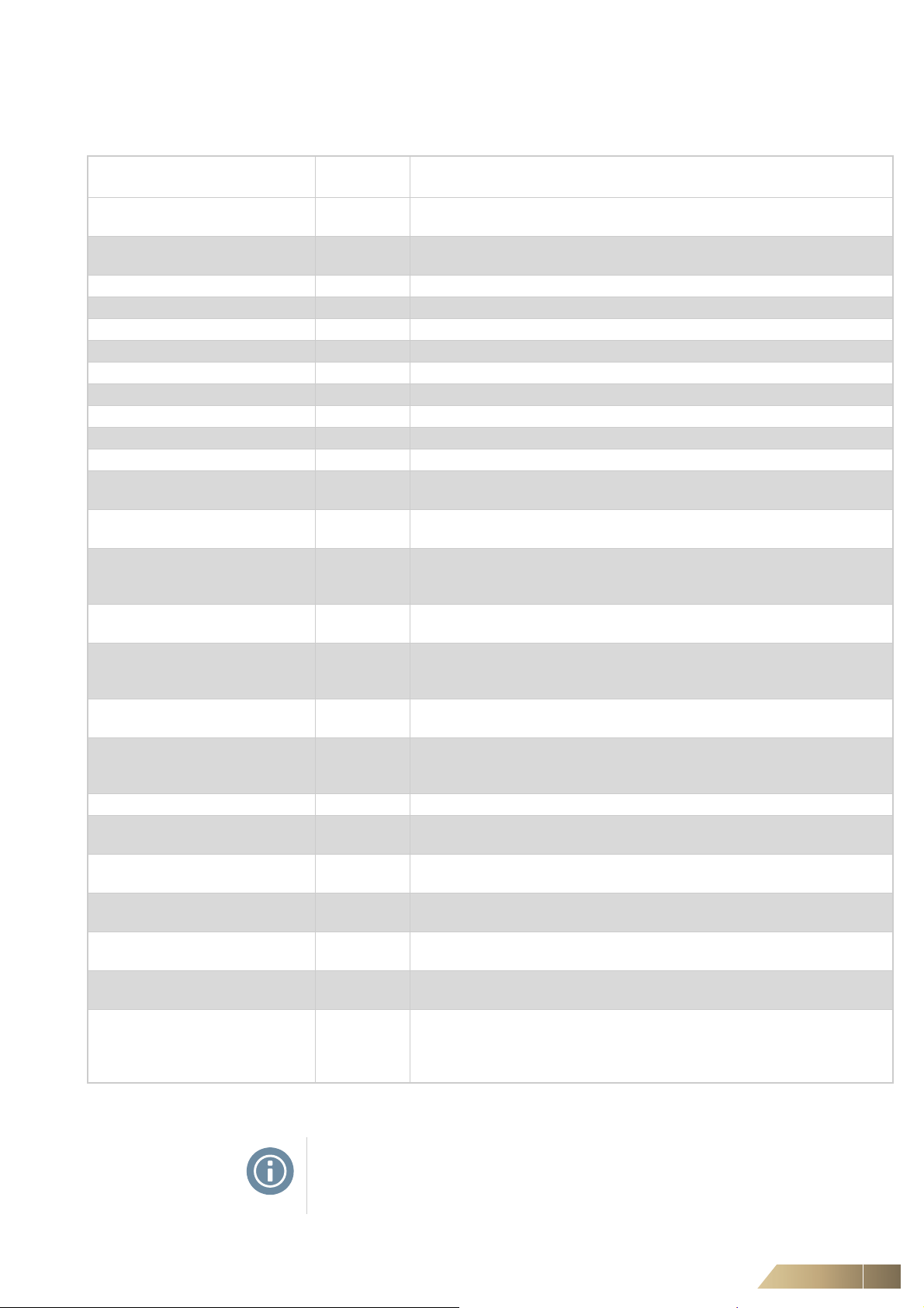
2.8 Air side accessories
The following accessory items can be delivered for the MultiMAXX HG Unit Heater:
Description Unit Type
Design
Code
Mixed-air module, type 1 ZH#.200# Outside air and recirculating air 90° displaced; galvanized metal sheet, Al
profile fins
Mixed-air module, type 2 ZH#.210# Outside air and recirculating air 90° displaced; galvanized metal sheet, Al
profile fins
Outside air blocking damper ZH#.230# Outside air feed; galvanized metal sheet, Al profile fins
Flexible canvas connection ZH#.2500 Elastic spacer, max. overall length 150 mm, steel sheet, plastic
Rectangular duct 150 ZH#.2600 Spacer, overall length 150 mm, steel sheet
Rectangular duct 1000 ZH#.2700 Spacer, overall length 1000 mm, steel sheet
Duct bend 90°, symmetrical ZH#.2800 Air duct with surrounding mounting frame, made of galvanized steel sheet
Duct bend 90°, asymmetrical ZH#.2900 Air duct with surrounding mounting frame, made of galvanized steel sheet
Wall air-intake hood ZH#.3100 Protection against rain with bird screen, made of galvanized steel sheet
External weather grill ZH#.3200 Protection against rain with bird screen, made of galvanized steel sheet
Contact protection grille ZH#.3300 End grille for accessories
Duct through slanted roof ZH#.3400 Air duct for a connection to the roof air-intake hood, made of galvanized steel
sheet
Roof air-intake hood ZH#.350# Duct flange with or without bag filter element, made of painted galvanized
steel sheet (RAL 9002)
Spare filter for air intake hood, roof
Bag-filter module ZH#.360# With filter G2 and G4 made of galvanized steel sheet
Spare filter for bag filter module
Mat-filter module
Spare filter for mat filter module
Roof duct with flat roof-duct base ZH#.4900 made of plastic and galvanized steel sheet
Frame for wall connection ZH#.5100 For connection of the air duct to the wall opening, made of galvanized steel
Terminating flange, pressure side ZH#.5200 For connecting the suction side accessories (only recirculating-air unit) made
Suspension type compact C ZH#.5300 For the suspension of a recirculating-air unit, wall/ceiling version; made of
Suspension type Studio ZH#.5400 For the suspension of a recirculating-air unit, only wall version;
Modular type suspension ZH#.550# For the suspension of a circulating/mixed-air unit in wall version or a recircu-
Ceiling suspension ZH#.5600
Tab. 2-6: Air side accessories
ZH#.3802
ZH#.3804
ZH#.3808
ZH#.3902
ZH#.3904
ZH#.3908
ZH#.370# With filter G2 and G4 made of galvanized steel sheet
ZH#.4002
ZH#.4003
ZH#.4004
ZH#.5601
ZH#.5602
ZH#.5603
Filter G2
Filter G4
Filter F7
with or without differential pressure switch
Filter G2
Filter G4
Filter F7
with or without differential pressure switch
Filter G2
Filter G3
Filter G4
sheet
of galvanized steel sheet
galvanized steel sheet
made of galvanized steel sheet
lating-air unit in ceiling version; made of galvanized steel sheet
Attachment without threaded rod, made of galvanized steel sheet
with threaded rod 1 m - M10; made of galvanized steel sheet
with threaded rod 2 m - M10; made of galvanized steel sheet
with threaded rod 3 m - M10; made of galvanized steel sheet
NOTE!
Detailed data on air side accessories provided in the "Data and Facts
of MultiMAXX HG".
FläktGroup DC-2011-0141-GB 2018-05/R5 • Subject to modifications 15
Specifications MultiMAXX HG
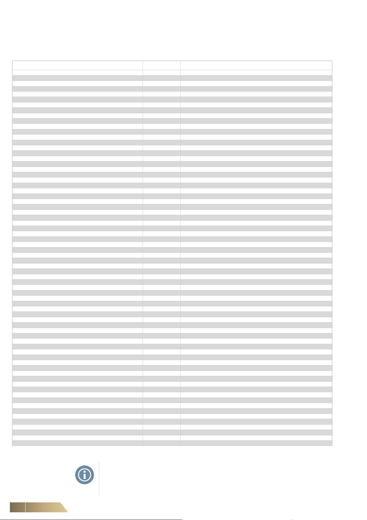
2.9 Accessories - exhaust gas lines, flue gas pipework
The following accessory items can be delivered for the unit heater MultiMAXX HG:
Description Type Dimensions - configuration
Pipe with sleeve ZHG.3780 Diameter 80 mm, length 0.22 m, Al
Pipe with sleeve ZHG.3710 Diameter 100 mm, length 0.22 m, Al
Pipe with sleeve ZHG.3880 Diameter 80 mm, length 0.17 m, Al
Pipe with sleeve ZHG.3810 Diameter 100 mm, length 0.17 m, Al
Pipe with sleeve ZHG.3980 Diameter 80 mm, length 0.31 m, Al
Pipe with sleeve ZHG.3910 Diameter 100 mm, length 0.35 m, Al
Pipe with sleeve ZHG.4080 Diameter 80 mm, length 0.5 m, Al
Pipe with sleeve ZHG.4010 Diameter 100 mm, length 0.5 m, Al
Pipe with sleeve ZHG.4180 Diameter 80 mm, length 1 m, Al
Pipe with sleeve ZHG.4110 Diameter 100 mm, length 1 m, Al
Pipe with sleeve ZHG.4280 Diameter 80 mm, length 2 m, Al
Pipe with sleeve ZHG.4210 Diameter 100 mm, length 2 m, Al
Coaxial pipe with sleeve ZHG.7080 Diameter 80/125 mm, length 0.5 m, Al
Coaxial pipe with sleeve ZHG.7010 Diameter 100/150 mm, length 0.5 m, Al
Coaxial pipe with sleeve ZHG.7180 Diameter 80/125 mm, length 1 m, Al
Coaxial pipe with sleeve ZHG.7110 Diameter 100/150 mm, length 1 m, Al
Coaxial pipe with sleeve ZHG.7280 Diameter 80/125 mm, length 2 m, Al
Coaxial pipe with sleeve ZHG.7210 Diameter 100(150 mm, length 2 m, Al
Elbow fitting 90° with sleeve ZHG.4380 Diameter 80 mm, metal mixture, Al
Elbow fitting 90° with sleeve ZHG.4310 Diameter 100 mm, metal mixture, Al
Coaxial elbow fitting 90° with sleeve ZHG.7380 Diameter 80/125 mm, metal mixture, Al
Coaxial elbow fitting 90° with sleeve ZHG.7310 Diameter 100/150 mm, metal mixture, Al
Elbow fitting 45° with sleeve ZHG.4480 Diameter 80 mm, metal mixture, Al
Elbow fitting 45° with sleeve ZHG.4410 Diameter 100 mm, metal mixture, Al
Coaxial elbow fitting 45° with sleeve ZHG.7480 Diameter 80/125 mm, metal mixture, Al
Coaxial elbow fitting 45° with sleeve ZHG.7410 Diameter 100/150 mm, metal mixture, Al
T-fitting 45° with a condensate container ZHG.4580 Diameter 80 mm, Al
T-fitting 45° with a condensate container ZHG.4510 Diameter 100 mm, Al
T-fitting with sleeve ZHG.4680 Diameter 80 mm, Al
T-fitting with sleeve ZHG.4610 Diameter 100 mm, Al
Condensate container ZHG.4780 Diameter 80 mm, Al
Condensate container ZHG.4710 Diameter 100 mm, Al
Pipe with sleeve and with condensate drain ZHG.4880 Diameter 80 mm, Al
Pipe with sleeve and with condensate drain ZHG.4810 Diameter 100 mm, Al
Windproof hood (wall) ZHG.4980 Diameter 80 mm, Al
Windproof hood (wall) ZHG.4910 Diameter 100 mm, Al
Coaxial windproof hood (wall) ZHG.7980 Diameter 80/125 mm, Al
Coaxial windproof hood (wall) ZHG.7910 Diameter 100/150 mm, Al
Roof air-intake hood ZHG.5080 Diameter 80 mm, Al
Roof air-intake hood ZHG.5010 Diameter 100 mm, Al
Coaxial weatherproof hood (ceiling) ZHG.9080 Diameter 80/125 mm, Al
Coaxial weatherproof hood (ceiling) ZHG.9010 Diameter 100/150 mm, Al
Flexi - pipe with sleeve - intake ZHG.5180 Diameter 80 mm, max. length 1 m. Al
Flexi - pipe with sleeve - intake ZHG.5110 Diameter 100 mm, max. length 1 m. Al
Flexi - pipe with sleeve - draft ZHG.5280 Diameter 80 mm, max. length 1 m. Al
Flexi - pipe with sleeve - draft ZHG.5210 Diameter 100 mm, max. length 1 m. Al
Connecting piece ZHG.9380 Diameter 80/125 mm, Al
Connecting piece ZHG.9310 Diameter 100/150 mm, Al
Reducer ZHG.5480 Diameter 80/100 mm, Al
Oversize sleeve ZHG 5680 Diameter 80 mm, rubber
Oversize sleeve ZHG 5610 Diameter 100 mm, rubber
Oversize sleeve ZHG 9680 Diameter 125 mm, rubber
Oversize sleeve ZHG 9610 Diameter 150 mm, Al
Roof duct for flat roof ZHG.5710 For the flue gas pipework diameter 80, 100 and 125 mm, plastic
Roof duct for flat roof ZHG.9710 For the flue gas pipework diameter 150 mm, Al
Duct through slanted roof ZHG.5810 For the flue gas pipework diameter 80, 100 and 125 mm, plastic
Chimney collar for the roof duct ZHG.5980 For the flue gas pipework diameter 80 mm, plastic
Chimney collar for the roof duct ZHG.5910 For the flue gas pipework diameter 100 mm, plastic
Chimney collar for the roof duct ZHG.9980 For the flue gas pipework diameter 125 mm, plastic
Set with 45° T-fitting ZHG.6080 Diameter 80/125 mm, Al
Set with 45° T-fitting ZHG.6010 Diameter 100/150 mm, Al
Set with 90° T-fitting ZHG.6180 Diameter 80/125 mm, Al
Set with 90° T-fitting ZHG 6110 Diameter 100/150 mm, Al
Set D90L ZHG.6380 Diameter 80/125 mm, Al
Set D90L ZHG.6310 Diameter 100/150 mm, Al
Horizontal installation set ZHG 6280 Diameter 80/125 mm, Al
Horizontal installation set ZHG 6210 Diameter 100/150 mm, Al
Pressure-side hose R 3/4" ZHG.0040 Length 0,4 m
Pressure-side hose R 3/4" ZHG.0070 Length 0.7 m
Pressure-side hose R 3/4" ZHG.0010 Length 1 m
Tab. 2-7: Accessories of the flue gas pipework and gas distribution
NOTE!
All exhaust gas conducting parts contain silicon gaskets (upon request, also seals
without silicon can be delivered). Detailed data on the flue gas pipework accessories
can be found in the "Data and Facts of MultiMAXX HG".
16 FläktGroup DC-2011-0141-GB 2018-05/R5 • Subject to modifications
MultiMAXX HG Shipping and Storage
3 S hipping and Storage
3.1 Shipping
The notices of the manufacturer must be taken into account for shipping and storage.
NOTE!
• After unpacking the heating unit, the shipment must be examined for correctness
and completeness on the basis of the delivery note.
• Ship and store unit heaters in original packing!
EQUIPMENT DAMAGE!
• After shipment, check to make sure that the unit is not damaged.
NOTE!
Incorrectly delivered quantities or damages caused by shipping must be entered
immediately in the shipping voucher, or possibly the goods should not be accepted
and the manufacturer or supplier immediately informed.
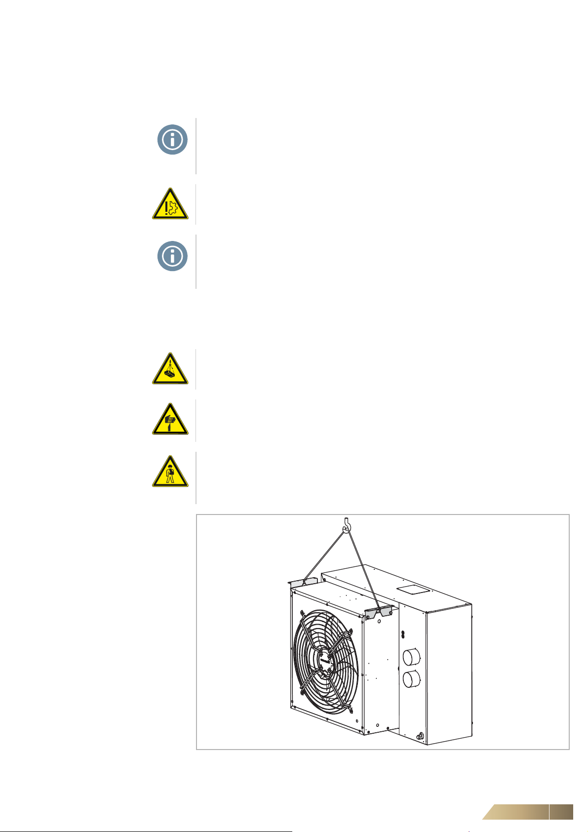
3.2 Shipping and handling of the unit
• Attach lifting gear to the designated points of the assembly unit.
Only lifting gear with sufficient load carrying capacity is allowed.
DANGER DUE TO OVERHEAD LOADS!
Do not move air heaters over people.
DANGER – SHARP CUTTING EDGES!
Use personal protective gear such as safety gloves, footwear and protective clothes
during transport.
PERSONAL INJURY!
Do not use damaged transport devices.
Air heaters can only be transported with a fork-lift truck if they are placed on a pallet.
Pay special attention to equal weight distribution.
Fig. 3-1: Transport of the unit MultiMAXX HG
FläktGroup DC-2011-0141-GB 2018-05/R5 • Subject to modifications 17

Shipping and Storage MultiMAXX HG
3.3 Storage
Protect MultiMAXX HG Air Heaters against moisture, soiling (dust and sand) and sun
/ radiant heat.
Store only in areas protected from weather influences, mildews, rodents, and
vibrations.
The unit heater or the regulator and other accessories may not be stored or operated
in areas with salty fog .
NOTE!
Allowable storage conditions:
Air temperature: -15 °C to +40 °C
Air humidity: max. 80% without condensation
18 FläktGroup DC-2011-0141-GB 2018-05/R5 • Subject to modifications
MultiMAXX HG Mounting
Suspension height
4 Mounting
NOTE!
When mounting the MultiMAXX HG units, observe the safety regulations and stand-
ards valid in the respective countries and the generally recognized rules of technology.
4.1 Load-bearing capacity of the installation site
NOTE!
The installation site must be suited as a durable and vibration-free weight bearer of
the unit heater, and be checked by a structural engineer or architect if necessary.
2 x 4 rivet nuts M8 on the sides of the fan module are provided for mounting the sus-
pension of the MultiMAXX HG Unit Heater (see Fig. 2-2). The fixing material is
included with the suspensions.
Unused M8 rivet nut openings should be closed with M8 screws from the transport
securing device.
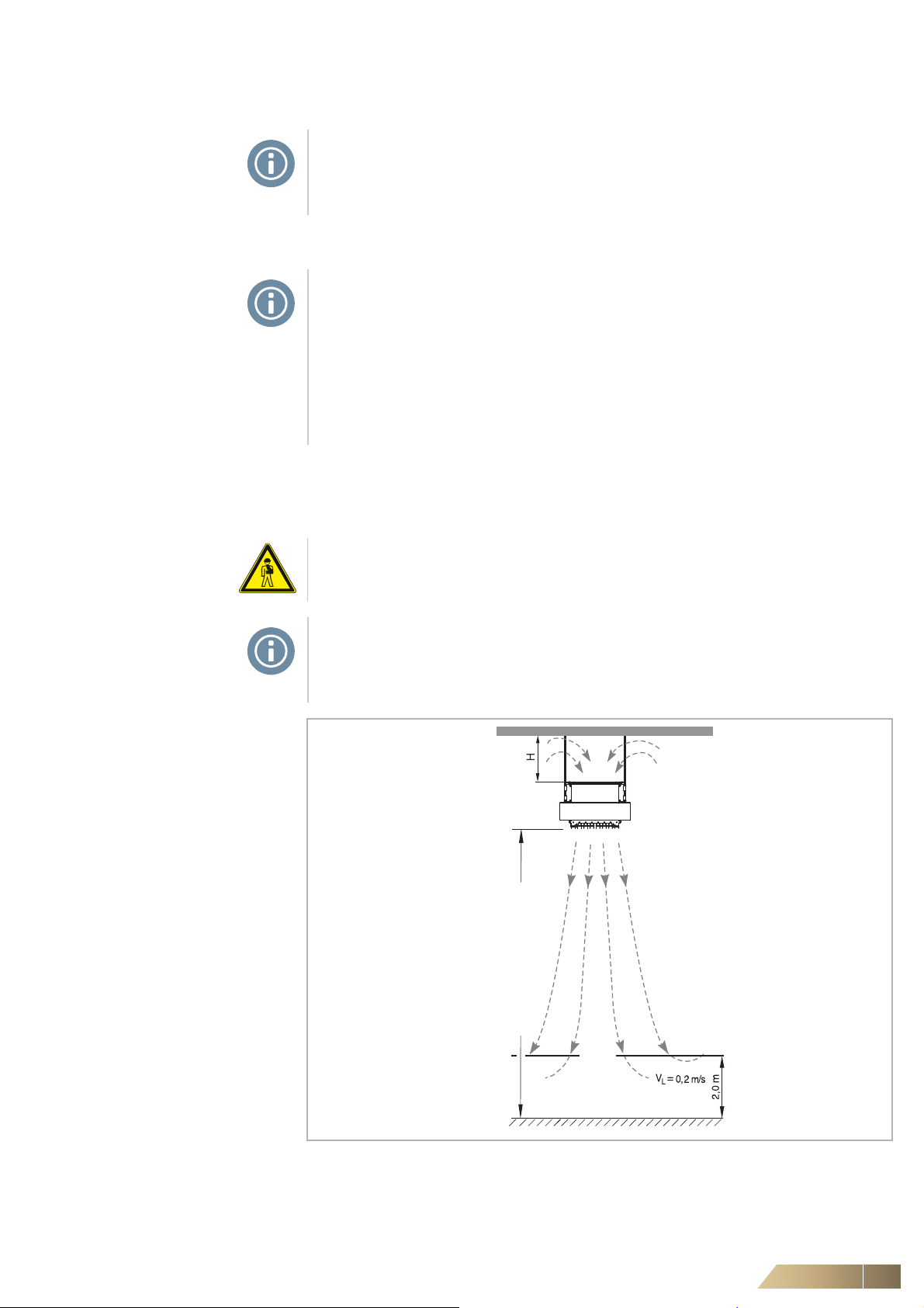
4.2 Ceiling mounting
Plan the suspension height, unit spacing (see Fig. 4-2) and
minimum spacing to the ceiling (see Fig. 4-1).
PERSONAL INJURY!
The minimum permissible height above the floor is 2.7 m.
NOTE!
We recommend that the suspension height of the unit from the floor to the lower
edge of the air outlet be selected in such a way (see Fig. 4-1) that two m above the
floor in the work area the air velocity is 0.2 m/s .
Fig. 4-1: Suspension height for ceiling mounting
FläktGroup DC-2011-0141-GB 2018-05/R5 • Subject to modifications 19

Mounting MultiMAXX HG
6 - 12 m
3 - 6 m
Max. air throw
Minimum ceiling spacing H (see Fig. 4-1)
Provide a minimum distance to ceiling to allow sufficient air circulation and ensure
adequate access for maintenance.
Model size 2 4
Spacing H [mm] 300 400
Max. suspension height
The maximum suspension height for the ceiling mounting varies depending on the
discharge temperature, lower speed stages and less air volume flow (results from the
pressure loss of the accessory or external pressure loss).
Examples of the mounting height for the respective types are listed in following table
(Tab. 2-4).
Unit spacing for ceiling mounting (see Fig. 4-2)
In order to achieve a favorable air distribution pattern of the occupied zone, we recommend the following unit spacing:
4.3 Wall mounting
Fig. 4-2: Unit spacing for ceiling mounting
Example of ceiling mounting with mixed-air module and ceiling suspension (ZHx.5602)
see Fig. 4-8
Please observe: minimum suspension height, air jet direction of discharge, unit spacing among each other (see Fig. 4-4) and minimum spacing to the wall (see Fig. 4-3).
PERSONAL INJURY!
The minimum permissible height above the floor is 2.7 m.
Fig. 4-3: Air throws with wall mounting
20 FläktGroup DC-2011-0141-GB 2018-05/R5 • Subject to modifications
 Loading...