

FläktGroup ACJB Installation, Operation, Maintenance And Spare Parts
AIR HEATING UNIT
HEATMASTER ACJB
INSTALLATION, OPERATION, MAINTENANCE AND SPARE PARTS
2
CONTENTS
OPERATION AND MAINTENANCE (FOR USER)
System, functions, main components ................................................................... 3
Control panel, operation ............................................................................................... 4
Maintenance, filter replacement ...............................................................................5
INSTALLATION (FOR INSTALLER AND SERVICE PERSONNEL)
Dismantling and installation of unit ....................................................................... 6
Capacity data ................................................................................................................... 6
Dimensions and weight ............................................................................................... 7
Connection diagrams
Unit with electric heater ...................................................................................... 8
Unit with water heater .........................................................................................9
Functions .........................................................................................................................10
Replacement of room temperature sensor (if applicable) ...........................11
ADJUSTMENT, COMMISSIONING (FOR INSTALLER AND SERVICE PERSONNEL)
Settings, Symbol descriptions ................................................................................ 12
Parameter lists .............................................................................................................. 13
Air Heating unit ACJB - Technical manual
MISCELLANEOUS
Spare parts ..................................................................................................................... 14
EC Declaration of Conformity ...................................................................................15
INFORMATION IN ACCORDANCE WITH ECODESIGN AND
REGULATION EU 2016/2281.
The ACJB is not B1, C2 or C4 air heating unit.
Type of fuel: Electricity.
Parameter Designation Value Unit
Capacity
Other
parameters
Nominal heating capacity
Minimum Capacity
Cover losses
Emission efficiency
Seasonal efficiency for
room heating
P
rated, h
P
F
h
s, flow
h
min
env
s, h
6.0 kW
0.0 kW
1.9 %
96.6 %
37.9 %
WARNING! THE APPLIANCE MAY BE USED BY CHILDREN OVER THE AGE OF 8, PERSONS (INCLUDING CHILDREN) WITH PHYSICAL,
SENSORY OR MENTAL DISABILITIES OR LACK OF KNOWLEDGE OR EXPERIENCE, PROVIDED THEY HAVE RECEIVED INSTRUCTION
OR INFORMATION ON SAFE USE OF THE APPLIANCE AND UNDERSTAND THE POTENTIAL RISKS. CHILDREN MAY NOT PLAY WITH
THE APPLIANCE. CHILDREN MAY NOT CLEAN OR PERFORM MAINTENANCE ON THE APPLIANCE WITHOUT SUPERVISION.
NOTE! INSTALLATION, ADJUSTMENT AND COMMISSIONING AS DESCRIBED
IN THESE INSTRUCTIONS MUST BE CARRIED OUT BY AN INSTALLER OR SERVICE PERSONNEL.
FläktGroup DC_9170GB_20190117_R2
We reserve the right to make changes without prior notice
Air Heating unit ACJB - Technical manual
!
SYSTEM, FUNCTIONS, MAIN COMPONENTS
3
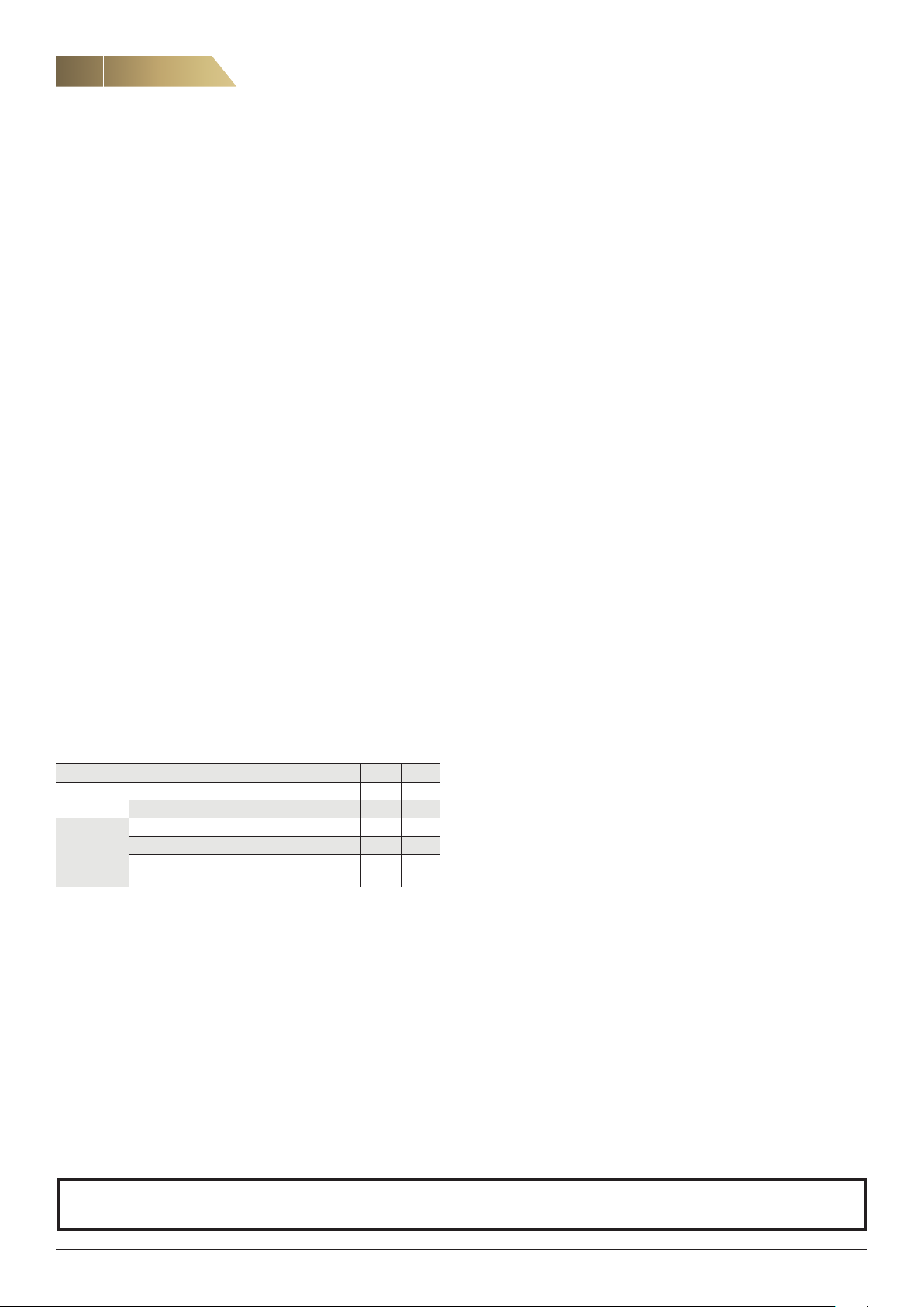
OVERVIEW OF THE AIR HEATING SYSTEM
Exhaust air
Outdoor air
Filter Filter
Fan
Heat exchanger
Heat recovery unit
THE UNIT’S MAIN COMPONENTS
Supply air
Extract air
Toilet
Bathroom
Scullery
Laundry room
Kitchen (cooker hood)
Air heating unit ACJB
Hallway
or similar
Control panel
Fan
Heater
(water/electric)
Warm supply air
Other rooms
to be heated
Filter
central area
Secondary air
SUMMER MODE
During the summer months when there is no need for heating, summer mode can be activated. This reduces the fan operation to 30% after a set time delay (normally 24 hours). Summer mode is indicated by
a LED on the control panel.
Summer mode is automatically deactivated when there is a need for
heating.
1 2 4 5 63
1. Coarse filter (G3) ISO Coarse
2. Fine filter (M5) ISO Coarse 85%
3. Secondary air fan
4. Control unit
5. Postheater (water/electrical)
6. Casing
SYSTEM DESIGN
An air heating system combines air-based heating and balanced ventilation with heat recovery.
The heat recovery units can be installed in a kitchen, store room, scul
lery or attic.
An air heating system uses the same ducts for ventilation and heating.
CONTROL
The control unit automatically controls the ACJB unit’s fan and
water or electric heater to maintain the desired temperature.
SETTINGS
The temperature, fan speed and other parameters are set in consultation with the installer/service personnel.
ELECTRICAL DATA
UNIT WITH ELECTRIC HEATING
Voltage: 400 V, 3-phase, 50 Hz
The electric heater operates in two stages: one stage with an output of
3 kW which is controlled steplessly via a pulser, and one fixed stage
with an output of 3 kW which is controlled via a contactor.
Fan motor Output, W Electric heater Output, W Rated output, W
175 2 x 3,000 6,180
-
UNIT WITH WATER HEATING
Voltage: 230 V, 1-phase, 50 Hz
Fan motor output, W Rated output, W
175 180
FläktGroup DC_9170GB_20190117_R2
We reserve the right to make changes without prior notice
4
CONTROL PANEL RDKZ-41-1, OPERATION
Air Heating unit ACJB - Technical manual
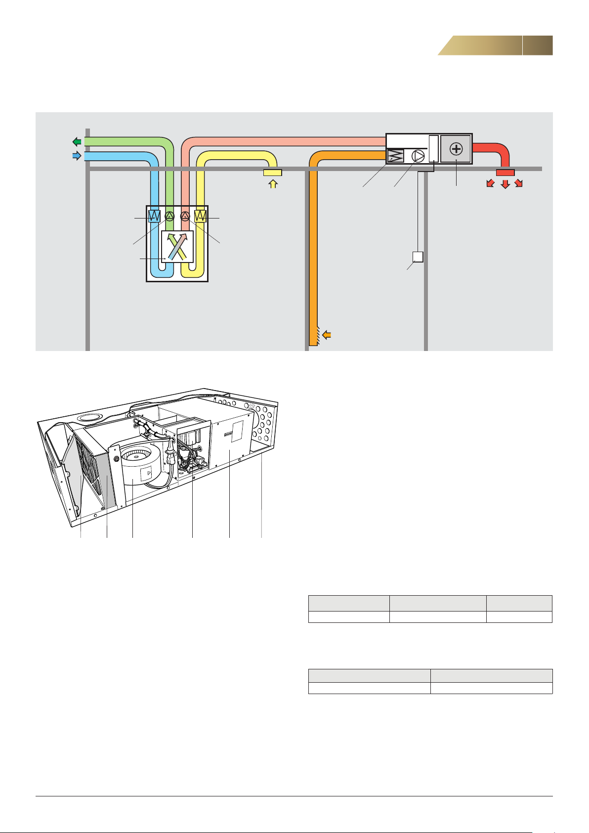
CONTROL PANEL RDKZ-41-1
Figure 1. Control panel RDKZ-41-1 with mains lead.
The operating mode is selected via the external control panel RDKZ-411, which should be installed in a suitable place, either on a wall or in a
wall box. Press the arrow button to select operating mode. The activat
ed mode is indicated by a LED.
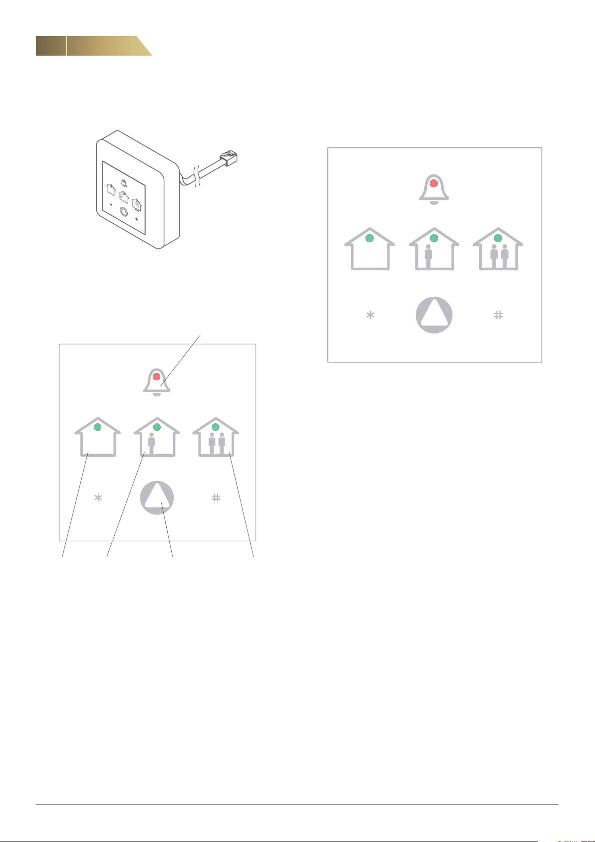
FILTER ALARM
SET DESIRED TEMPERATURE
The temperature is set via control panel RDKZ-41-1.
Indicates tens
(10–90)
SUMMER MODE
NORMAL FORCED
-
Each press reduces
the set temperature
by 1 °C
Figure 3. Setting of desired temperature.
Saves the set
temperature
1. Check the current set temperature by pressing either the * or
# button once.
Then count how many times the NORMAL and FORCED symbols
flash.
Note that the NORMAL symbol indicates tens and the FORCED symbol
indicates ones.
Indicates ones
(1–9)
Each press raises
the set temperature
by 1 °C
NORMALSUMMER MODE
(for selecting operating mode)
Figure 2. Operating modes on control panel (RDKZ-41-1).
FORCEDArrow button
NORMAL MODE
The air heating unit automatically controls the fan speed to maintain
the desired temperature.
FORCED MODE
The fan goes up to maximum flow. This function can be used to distribute surplus heat through the house, for instance if a heating stove
is used.
The unit operates in forced mode for 120 minutes, and then returns to
NORMAL mode. If forced ventilation is required for only a short time, it
can be terminated manually by pressing the arrow button and select
ing NORMAL mode.
Example: If the NORMAL symbol flashes twice and the FORCED symbol
flashes three times, the temperature is currently set at 23º C.
2. To change the temperature, press * to reduce it or # to increase it.
3. After setting the desired temperature, press ARROW to save and
return to normal mode on the control panel.
-
FläktGroup DC_9170GB_20190117_R2
We reserve the right to make changes without prior notice
Air Heating unit ACJB - Technical manual
MAINTENANCE, FILTER REPLACEMENT
5
MAINTENANCE
Wipe the unit’s casing clean with a cloth. Do not use solvents.
The filter should normally be replaced every 6 months, but sometimes
more frequent replacement is needed.
A timer is set at six months, and the alarm light on the control panel
flashes when it is time to replace the filter.
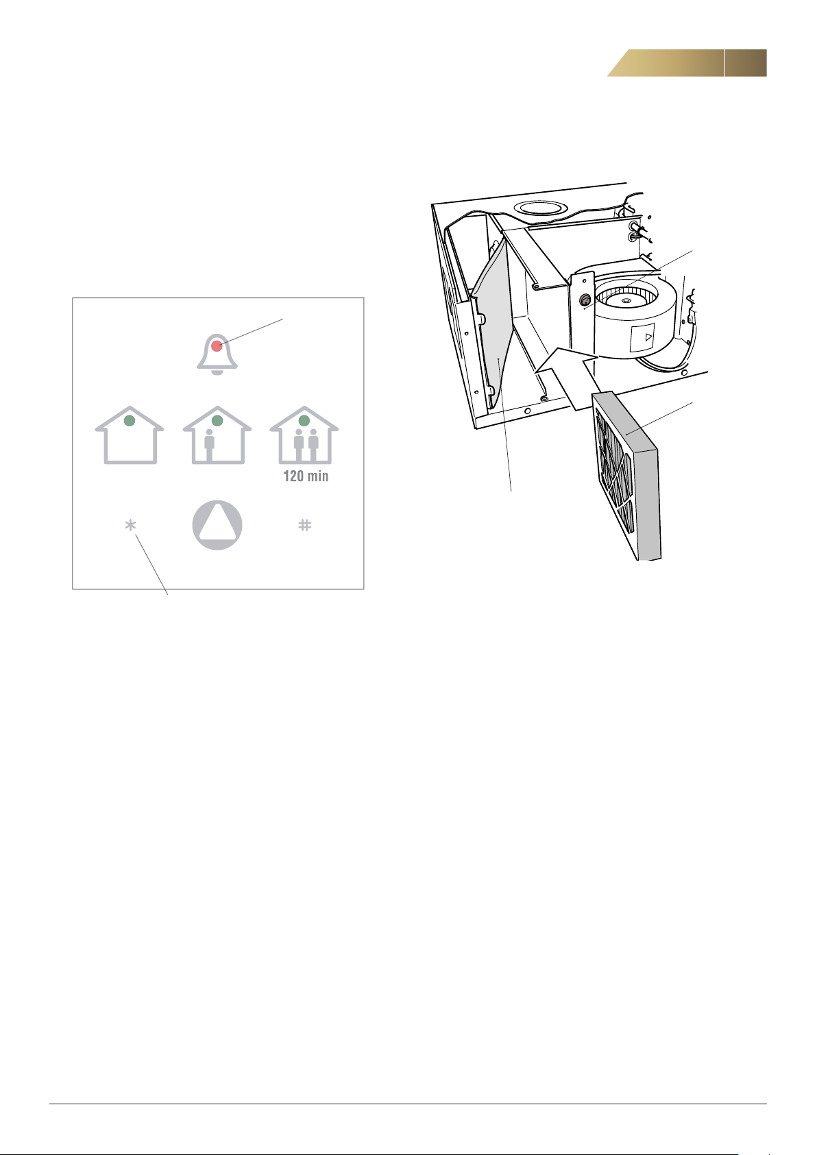
To replace the filter, follow the steps below.
Alarm light
REPLACEMENT OF FILTERS
Power switch
!
Fine filter
Coarse filter
Resetting of filter
alarm
Figure 4.
1. Switch off the unit with the power switch.
2. Open the filter hatch by turning the knobs.
3. Pull out the filters, see figure 5.
4. Insert new filters.
5. Close the filter hatch.
6. Start the unit.
7. Reset the filter alarm by pressing (*) for at least 10 seconds,
see figure 4.
Figure 5. Location of filters in unit.
FläktGroup DC_9170GB_20190117_R2
We reserve the right to make changes without prior notice
 Loading...