

Page 1
INTRODUCTION
Your new Model 45135 Battery Diagnostic Tester employs
conductance testing to determine the condition of the battery.
The patented circuit eliminates the need for time consuming
CCA input or conversions to other rating systems. When the
TEST button is pressed, the 45135 will immediately display
BOTH the percent available capacity of the battery and the
condition of the battery. The 45135 also tests 12/24/36V
alternator and starter systems.
1
YA2612A
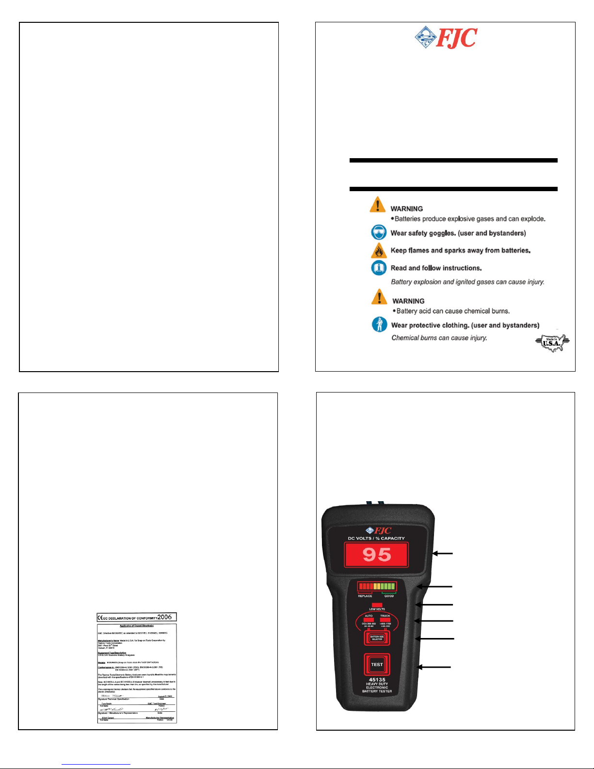
Displays % Capacity &
DC Volts
Bar Graph Indicator
Low Volts Indicator
Battery Size Selector
Press to Test Battery
Battery Size Indicator
SPECIFICATIONS
Battery Size Range
Auto: 390 to 650 CCA
40 to 60 Ah
Truck: >650 to 1700 CCA
>60 to 250 Ah
Battery Condition
Good: 80 to 100%
Marginal: between 70 to 80%
Replace: below 70%
DC Volt Range: 6V to 49.9V
DC Volts Accuracy: ± 2% Reading
Capacity/Volts Display: 4 LED’s- 3 ½ Digit
Bar-graph Display: 10 color-coded LEDs
Operating Temperature: 32°F to 120°F
Weight: .75 LBS
Dimensions: 7.5” x 3.5” x 1” H
Jaw Opening: 1.25”
User Manual
Model 45135
HEAVY DUTY
Battery Condition & Charging
System Tester
Tests 12V Auto and Truck Batteries
and12/24/36V charging systems
& 42V mild hybrid vehicles
RETURN FOR REPAIR POLICY
Every effort has been made to provide reliable, superior quality
products. However, in the event your instrument requires repair, call
FJC, Inc.:
For Service
704-664-3587
WARRANTY POLICY
The 45135 Battery Diagnostic Tester is warranted to be free of
defects in materials and workmanship for a period of two years from
the date of purchase. This warranty applies to all repairable
instruments that have not been tampered with or damaged through
improper use including unauthorized opening of the unit. Please ship
warranty units that require repair freight prepaid to Service Center
along with proof of purchase, return address, phone number and/or
email address.
Made in USA S
Page 2
Checking Charging System
(Alternator)
CHARGING SYSTEM TEST
Note: Prior to performing this test, check the battery condition to
make sure it is in good condition. (See In Vehicle Battery Test
Instructions).
1. Check first for a loose, worn or broken alternator belt. If
okay, proceed to #2.
2. Connect the red clip to the positive battery terminal and
the black clip to the negative terminal and start engine. For
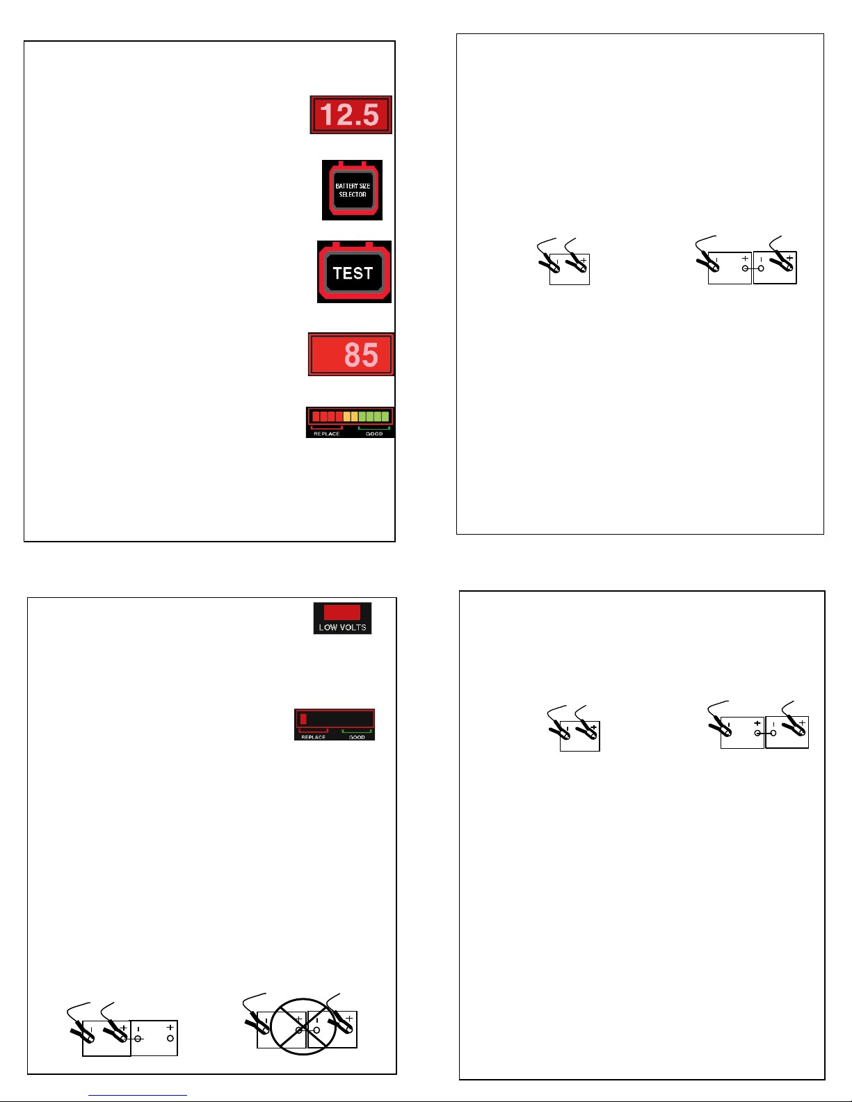
series batteries connect the test clips as shown below.
3. With engine running and lights on, the real time alternator
output voltage will be displayed. The reading should display
between 13.0 and 15.0 volts for 12V charging systems.
Check manufacturer’s specifications for 24V and 36V
systems. NOTE: Consult shop manual for instructions on
testing 42V mild hybrid systems.
4. Low charging voltage: check belts for slippage. Check
connections from the alternator to the battery. If no problems
are found, replace the alternator.
5. High charging voltage: Check for loose connections
including the ground connection. If OK, replace the voltage
regulator. Newer alternators house the regulator inside. In
this case replacing the alternator is necessary.
4
Series
Connection
Individual
Connection
Checking Battery Condition
Out of Vehicle Testing
1. Connect the red clip to the positive battery
post and the black clip to the negative post*.
The battery voltage will be displayed. When
testing 24V/36V battery packs, connect to the
battery posts for each individual 12V battery.
2. For AUTO batteries 390 to 650 CCA (40 to
60 Ah) no size selection is necessary
(default size). The Auto indicator LED will be
on.
For TRUCK batteries >650 to 1700 CCA (>60
to 250 Ah) press selector switch once. The
LED indicator will switch to the TRUCK
position.
3. Press and hold down the Test Button until
the final reading is displayed.
The DIGITAL DISPLAY shows PERCENT
AVAILABLE CAPACITY. The Display and
Bargraph will remain on until the Test Button is
released.
4. The color--coded LED BARGRAPH will
show GOOD (Green) MARGINAL (Yellow) or
REPLACE (Red).
*When testing high capacity truck batteries, make sure clips
make a solid connection with battery post.
Note: Some batteries may display above 100%. This means that
the available capacity is greater than the rated capacity
2
STARTER TEST
Note: Check the battery condition to make sure it is in good condition
before performing this test. (See In-Vehicle Battery Test Instructions
page 3).
1. Connect the red clip to the positive battery terminal and
the black clip to the negative terminal. For series batteries
connect the test clips as shown below.
2. Disengage the ignition. (Check manufacturer’s
instructions). Read the voltage displayed while cranking the
starter.
3. Cranking Voltage is Normal: For 12V systems the
normal cranking voltage at the battery should be equal to or
greater than 9.6 volts*.
4. Cranking voltage is Low: If the cranking voltage is less
than 9.6 volts*, starting system has a problem. Check wires,
connections and starter.
Check manufacturer’s specifications for 24V and 36V
systems. NOTE: Consult shop manual for instructions on
testing 42V mild hybrid systems.
Converting to CCA, Ah, DIN, JIS, EN
If required, the available CCA or Ah, can easily be
determined by multiplying the percent displayed times the
battery’s original rating. For example, a 600 CCA battery
with 80% capacity available would have 480 CCA (.80 x
600) available.
5
Series
Connection
Individual
Connection
Low Volt Indicator
Batteries that test Marginal or (just below Marginal) when the
Low Volts LED indicator is on (below 12.3 Volts on 12V
systems and below 24.6 Volts on 24 Volts systems) should be
recharged and retested for more accurate results.
Bad Cell Indicator
Capacity displayed below 20% and only 1 red led on the bargraph indicates that the battery has a defective cell.
Defective battery cells are usually open or shorted and the
battery must be replaced.
In Vehicle Testing
(Checking Battery Condition)
1. Engine should be off. Turn off all accessory loads.
2. Remove surface charge (battery voltage is greater than 12.8
Volts) by turning on the headlights for 15 seconds.
3. Follow instructions for Out of Vehicle Testing (see Page 2).
4. When testing batteries in 24/36 Volt systems, test each
individual 12V battery separately. The 45135 will display only
the battery pack voltage when connected to two or more 12
Volt batteries-not the capacity of the pack when the TEST
button is pressed.
3
 Loading...