

Page 1
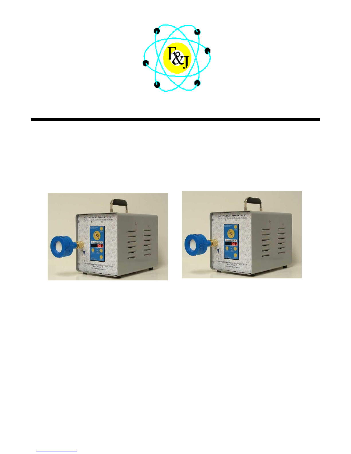
DF-75L-Li
DF-75L-AC
F&J SPECIALTY PRODUCTS, INC.
The Nucleus of Quality Air Monitoring Programs
EMERGENCY RESPONSE AIR SAMPLING
SYSTEM
Digital Flowmeter Technology 75 LPM DF Series
TECHNICAL MANUAL
Rev.: 04 November 2013
F:\MARKETING\TECHNICAL MANUALS\Air Samplers\DF Battery TECH MANUALS\DF-75 LPM SERIES.doc
Page 2

2
Page
General Description and Specifica tio ns
3 – 6
Hazard Warning Labels
7
Installation Instruct ions
8
Operating Features and Instructi ons
9 – 21
Filter Holders
Sensors
Corrections to Reference T and P
Low Voltage Limiting System Description
22
Calibration Instructions
23 – 25
Maintenance Instructions
26
Spare Parts List
27 – 28
Electrical Wiring Diagrams
29 – 30
Warranty Information and Limitation of Liabi lity
31
Service Information
32
Contact Information
33
TABLE OF CONTENTS
Copyright © 2005 F&J SPECIALTY PRODUCTS, INC.
This operator manual and information contained herein is proprietary to
F&J SPECIALTY PRODUCTS, INC. and shall not be reproduced, copied in whole or in part,
adapted or disseminated without the express written consent of
F&J SPECIALTY PRODUCTS, INC.
F:\MARKETING\TECHNICAL MANUALS\Air Samplers\DF Battery TECH MANUALS\DF-75 LPM SERIES.doc
Tel: (352) 680-1177 / Fax: (35 2) 680-1454 / Email: [email protected]
Page 3
3
GENERAL DESCRIPTION:
NOTABLE FEATURES:
EMERGENCY RESPONSE SAMPLING SYSTEM
— Digital Flowmeter Technology —
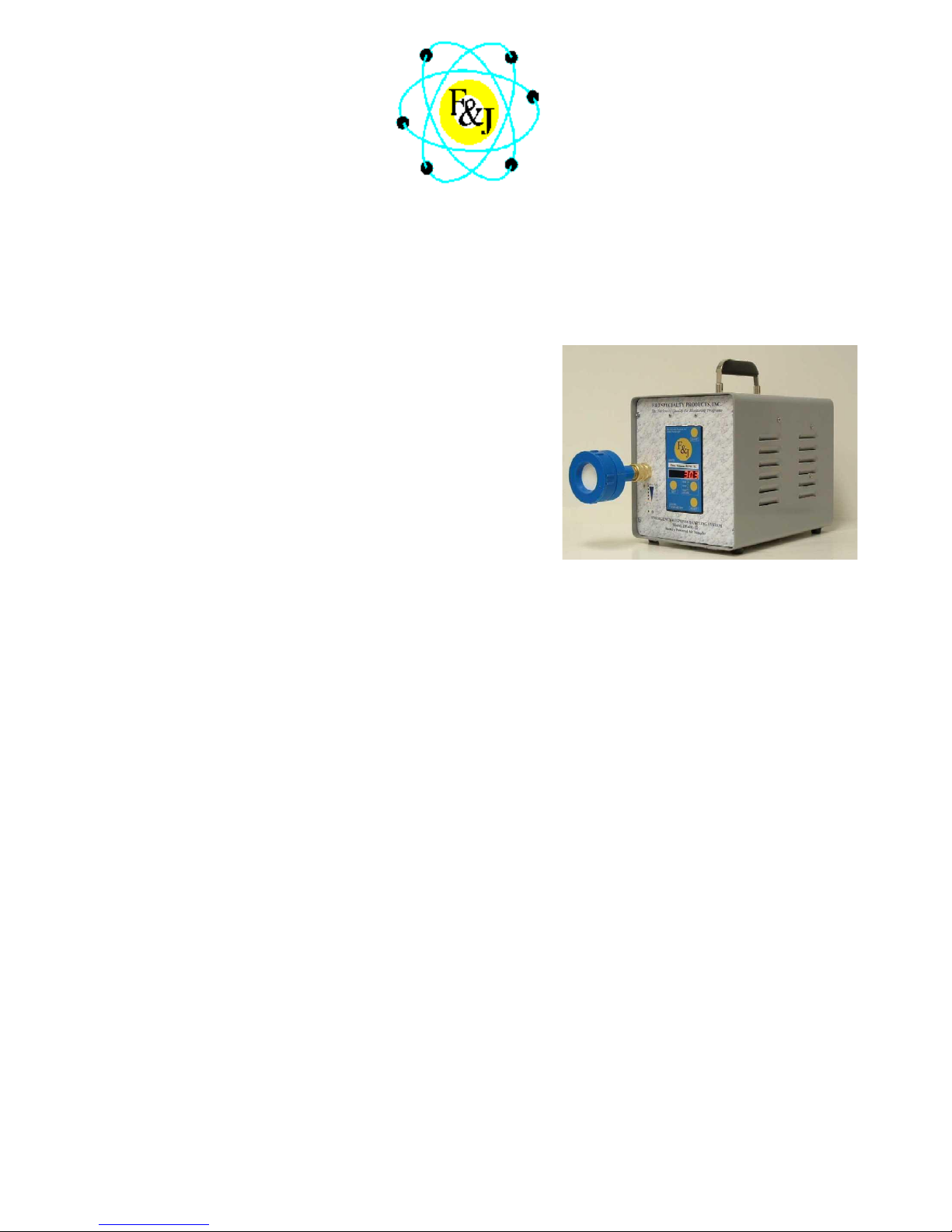
F&J Model DF-75L-Li
State-of-the-Art Electronics
Operating Modes
— Line Power (110VAC – 250VAC)
— On-Board Batteries
— Automobile Cigarette Lighter
Long-lasting Lithium ion battery
Battery Charging Circuit operable from Line Power
Input
Lightweight — ~17.5 lbs. (8.0 kg)
Maximum Flow: 65 to 75 LPM; typical
Bright LED Display
Automatic Flow Control Feature
Flowrate and Volume totalizations displayed are
corrected to a factory settable Reference
Temperature and Pressure (4 options available)
Auto shut-off on time or volume
Battery Life Indicator
F&J Model DF-75L-Li is a lightweight, small footprint, DC voltage powered air sampling system operable
from (1) on-board 14.8 VDC; 15.6 Ah Lithium ion battery, (2) line power, or (3) automobile cigarette lighter
socket.
The DF-75L-Li is well suited for emergency response sampling activities where users do not know whether
line power will be available and for alternative energy power source applications when line power is not
available.
The automatic flow control feature with the F&J Digital Flowmeter technology provides maximum
flexibility for emergency response sampling responsibilities. The set flowrate is maintained automatically in
case of dust loading and does not require operator attention.
Typical flow range is 30-75 SLPM (1.1 -2.6 SCFM).
Rev.: 20 May 2008
F:\MARKETING\TECHNICAL MANUALS\Air Samplers\DF Battery TECH MANUALS\DF-75 LPM SERIES.doc
Tel: (352) 680-1177 / Fax: (35 2) 680-1454 / Email: [email protected]
Page 4
4
DF-75L-Li Battery Powered Air Sampler Specifications
Pump Type: Dual diaphragm high efficiency
Standard Combination Filter Holders Available:
FILTER
MODEL
CHARCOAL
DIMENSIONS
PARTICULATE
DIAMETER
FJ-05P
F&J Model B
2” or 50 mm
FJ-21P
F&J Model C
2” or 50 mm
FJ-35P
F&J Model B
47 mm
FJ-46P
F&J Model C
47 mm
FJ-51P
F&J Model M
2” or 50 mm
FJ-53P
F&J Model M
47 mm
Flow /Volume: SLPM/SL
28.5
Maximum Flowrate:
75 LPM – Typical w/47 mm FP47M glass fiber media
100 LPM – Free air flow capacity
Power Source:
Internal –
14.8 VDC Battery Pack
Lithium Ion; 15.6 Ah
External –
Line Power; 110VAC or 250VAC
Automobile Cigarette Lighter – 12VDC
Battery Charging System:
Internal System which charges from line Power.
Operating Time on Batteries:
8 - 10 hours @ 56 LPM w/FP-47M
glass fiber media
Current Draw: 3 A maximum
Filter Holder Fitting: 3/8 FNPT quick disconnect
Handle: Durable metal
Weight: 15.3 lbs. (7 kg)
Dimensions: 8”×9”×12” (20 × 23 × 30 cm)
Display: Bright LED (6 character; 1.2 cm H)
Elapsed Time: DD:HH:MM up to 168 hours
Flow Control:
Adjustable from keypad between 30-75 LP M
Flow Accuracy: ±4.0% of Full Scale
Factory Settable Reference T and P
Classical STP 0ºC, 1 ATM
Normal T and P 20ºC, 1 ATM
Modified Normal T and P 70ºF, 1 ATM
Standard Ambient T and P 25ºC, 1 ATM
OPTIONS:
Data Storage Device (P/N: 232FCDSD)
1 GB Secure Digital Card (P/N: 372239)
Flash card Reader (P/N: SDDR-199-A20)
F:\MARKETING\TECHNICAL MANUALS\Air Samplers\DF Battery TECH MANUALS\DF-75 LPM SERIES.doc
Tel: (352) 680-1177 / Fax: (35 2) 680-1454 / Email: [email protected]
HOLDER
CARTRIDGE
PAPER
Available Engineering Units for Flow and Volume:
sccm/ scc
SLPM / SLP
SCFM / SCF
SCMH / SCM
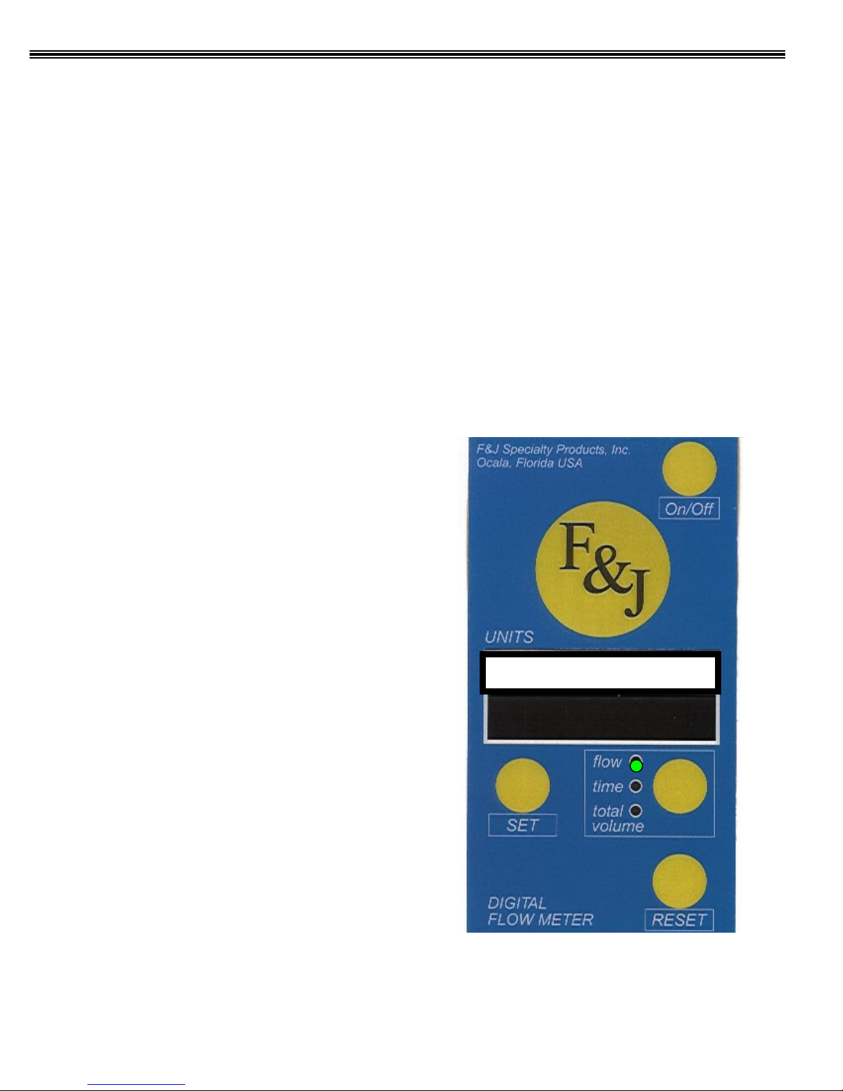
Digital Flowmeter Keypad/Display
Page 5
5
GENERAL DESCRIPTION:
F&J Model DF
operable from (1) on
such as solar panels or other alternative energy sources.
The DF
whether line power will be available
power is not available. The unit may be operated from solar po
either the AC input or DC input.
The automatic flow control feature with the F&J Digital Flowmeter technology provides maximum
flexibility for emergency response sampling responsibilities. The set flowrate is maintained
au
Typical flow range is 30
Rev.: 21 May 2008
NOTABLE FEATURES:
EMERGENCY RESPONSE SAMPLING SYSTEM
— Digital Flowmeter Technology —
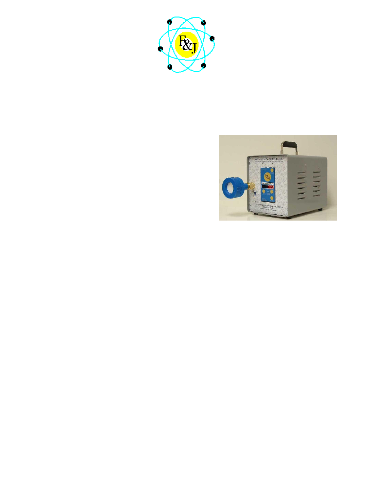
F&J Model DF-75L-AC
State-of-the-Art Electronics
Operating Modes
— Line Power (110VAC – 250VAC)
— Automobile Cigarette Lighter
Lightweight — ~11 lbs. (52,9 kg)
Maximum Flow: 65 to 75 LPM; typical
Bright LED Display
Automatic Flow Control Feature
Flowrate and Volume totalizations displayed are
corrected to a factory settable Reference Temperature
and Pressure (4 options available)
Auto shut-off on time or volume
-75L-AC is a lightweight, small footprint, DC voltage powered air sampling system
-board 14.8 VDC; 15.6 Ah Lithium ion batteries, (2) a 12-15 VDC power source
F:\MARKETING\TECHNICAL MANUALS\Air Samplers\DF Battery TECH MANUALS\DF-75 LPM SERIES.doc
-75L-AC is well suited for alternative energy air sampling activities where users do not know
and for alternative energy power source applications when line
wer or wind power source through
tomatically in case of dust loading and does not require operator attention.
-75 SLPM (1.1 -2.6 SCFM).
Tel: (352) 680-1177 / Fax: (35 2) 680-1454 / Email: [email protected]
Page 6
6
DF-75L-AC AC/DC Powered Air Sampler Specifications
Pump Type: Dual diaphragm high efficiency
Maximum Flowrate:
75 LPM
100 LPM
Power Source:
Current Draw:
Filter Holder Fitting:
Handle:
Weight:
Dimensions:
Operating Temperature Ranges:
Display:
Elapsed Time:
Flow Control:
Adjustable from keypad between 30
Flow Accuracy:
Factory Settable Reference T and P
OPTIONS:
Standard Combination Filter Holders Available:
FILTER
MODEL
CHARCOAL
DIMENSIONS
PARTICULATE
DIAMETER
FJ-05P
F&J Model B
2” or 50 mm
FJ-21P
F&J Model C
2” or 50 mm
FJ-35P
F&J Model B
47 mm
FJ-46P
F&J Model C
47 mm
FJ-51P
F&J Model M
2” or 50 mm
FJ-53P
F&J Model M
47 mm
Flow /Volume: SLPM/SL
60.0
– Typical w/47 mm FP47M glass fiber
media
– Free air flow capacity
Line Power; 110VAC or 250VAC
Automobile Cigarette Lighter – 12VDC
4 A maximum
3/8 FNPT quick disconnect
Durable metal
11 lbs. (5 kg)
8”×9”×12” (20 × 23 × 30 cm)
0ºF to 122ºF (-18ºC to 50ºC)
Bright LED (6 character; 1.2 cm H)
DD:HH:MM up to 168 hours
-75 LPM
± 4.0% of Full Scale
Classical STP 0ºC, 1 ATM
Normal T and P 20ºC, 1 ATM
Modified Normal T and P 70ºF, 1 ATM
Standard Ambient T and P 25ºC, 1 ATM
Data Storage Device (P/N: 232FCDSD)
1 GB Secure Digital Card (P/N: 372239)
Flash card Reader (P/N: SDDR-199-A20)
HOLDER
CARTRIDGE
PAPER
Available Engineering Units for Flow and Volume:
sccm/ scc
SLPM / SLP
SCFM / SCF
SCMH / SCM
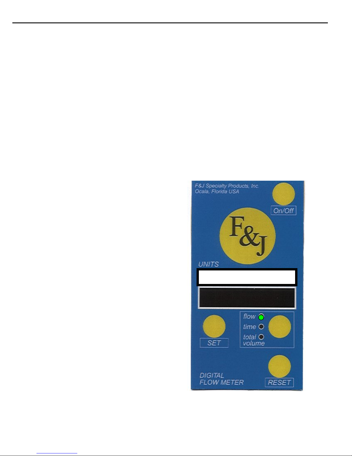
Digital Flowmeter Keypad/Display
F:\MARKETING\TECHNICAL MANUALS\Air Samplers\DF Battery TECH MANUALS\DF-75 LPM SERIES.doc
Tel: (352) 680-1177 / Fax: (35 2) 680-1454 / Email: [email protected]
Page 7
7
HAZARD ALERT LABELS
The following is an explanation of the two (2) different types of hazards:
WARNING
CAUTION
This is the hazard aler t symbol:
This symbol is utilized throughout the manual to notify the user or maintenance
personnel to pr ocee d w it h cau tio n.
When you see this symbol, be aware that personal injury or property damage is possible.
The hazard is explaine d in text following the symbol.
Read this information carefully before proceedings.
Severe personal injury or death can
occur if hazard is ignored.
Minor injury or property damage can
occur if hazard is ignored.
F:\MARKETING\TECHNICAL MANUALS\Air Samplers\DF Battery TECH MANUALS\DF-75 LPM SERIES.doc
Tel: (352) 680-1177 / Fax: (35 2) 680-1454 / Email: [email protected]
Page 8
8
Installation Instructions for DF Battery Air Samplers
CAUTION
WARNING
The 75 LPM DF Battery Emergency Response Air Sampling System has been shipped in a corrugated
box(es). Open each container, remove the air sampler from the shipping container and perform the
following inspections:
1. Confirm that the instrument calibration documentation arrived with the unit.
2. Confirm that the serial number and model number on the instrument Manufacturer’s
Data Plate matches the information stated on the calibration documents.
3. Confirm the line p ower requirements stated on the Manuf acturer’s Data Plate matches
the line power available.
4. Confirm that the instrument as received has no visible damage or loose components.
Particularly check for loose screws and that no observable damage to the air sampler
has occurred in transit.
5. Plug the air sampler into the local line power using the power cord provided after
confirmation of line power compatibility in step 3 above. If a local style plug is
required, install the plug in accordance with local electrical code prior to proceeding.
Plug the unit into a grounded receptacle.
NOTE: F&J recommends that the Air Sampler is operated to the point of discharge,
followed by a complete charge on a once per month frequency.
6. Refer to the operating instructions part of this manual titled “OPERATING
FEATURES and INSTRUCTIONS” for instructions on how to operate the instrument.
7. Install the filter media to be utilized with the instrument.
8. Turn on the DFM electronics by pressing the On/Off button on the DFM keypad. The
button is located in the upper-right corner of the DFM.
9. After referring to the operating instructions portion of this manual and mastering the
basic operating techniques, confirm the unit air flow sensors are functioning properly by
setting various flow rates, then viewing the DFM display.
The instrument may now be placed in service. Please refer to the operating instruction portion of this
manual for details on the operation of these instruments.
F:\MARKETING\TECHNICAL MANUALS\Air Samplers\DF Battery TECH MANUALS\DF-75 LPM SERIES.doc
Tel: (352) 680-1177 / Fax: (35 2) 680-1454 / Email: [email protected]
Page 9
9
OPERATING FEATURES and INSTR UCTIONS
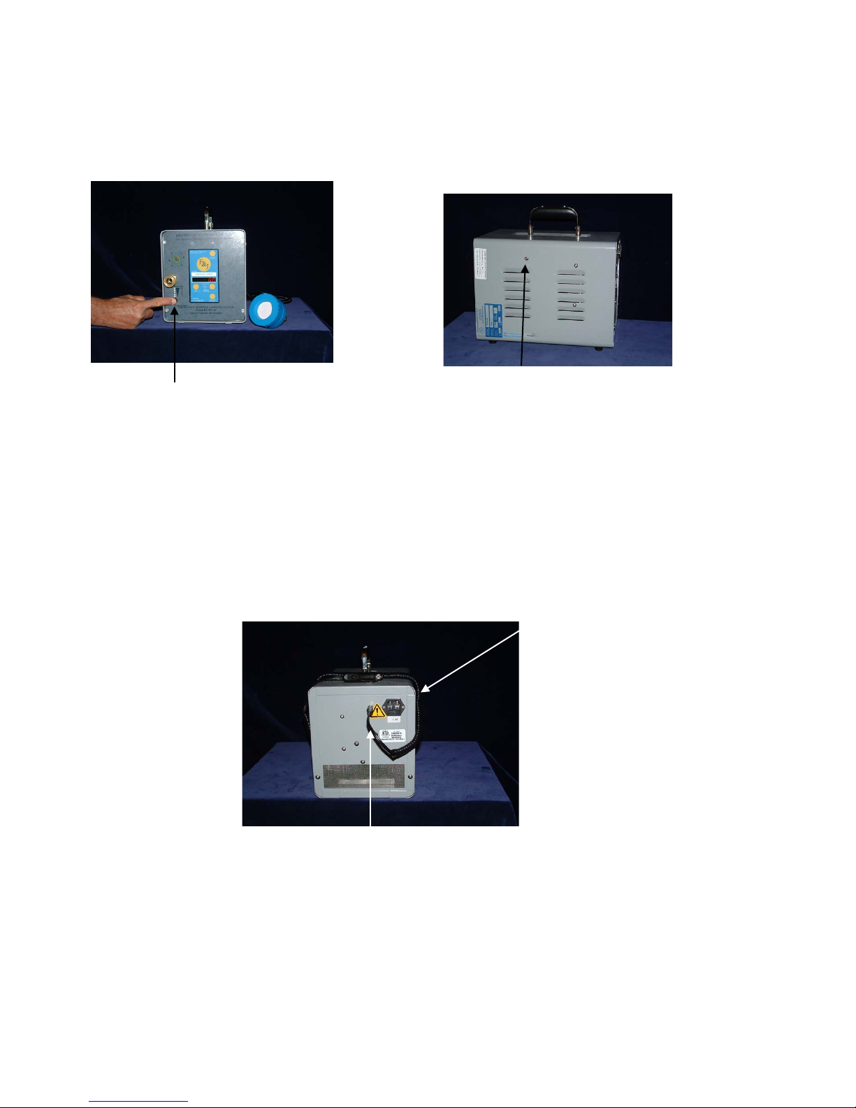
Battery Capacity Indicator
External DC Power Input
AC Receptacle
RS 232 Port
Figure 1
Figure 3
The 75 LPM DF Battery Series air samplers have all the operational components conveniently
accessible to the user. Model DF-75L-AC and DF-75L-Li air sampler’s pertinent components are
illustrated below in Figure 1 through Figure 3.
DF-75L-AC and DF-75L-Li
Figure 2
DF-75L-Li and DF-75L-AC Rear View
F:\MARKETING\TECHNICAL MANUALS\Air Samplers\DF Battery TECH MANUALS\DF-75 LPM SERIES.doc
Tel: (352) 680-1177 / Fax: (35 2) 680-1454 / Email: [email protected]
Page 10

10
OPERATING FEATURES and INSTR UCTIONS (Cont.)
POWER SOURCE
The 75 LPM DF Battery air samplers can be powered from any of the following power sources:
1. A 110VAC or 230VAC line power via the three-prong electrical connector at the rear of the
enclosure. This line power is converted to 12 VDC power through a universal transformer
accepting AC line voltage from 100VAC to 250VAC.
2. A 12 VDC Automobile Cigarette Lighter or Accessory socket. This connection is located at
the rear of the air sampler.
3. An internal 12 VDC lead acid or 14.8 VDC Lithium ion battery when external AC or DC
power is not available. The AC line voltage will charge the internal lead acid or Lithium ion
battery.
ON-OFF SWITCH
The ON/OFF switch is on the Digital Flowmeter. This enables the user to turn the air sampler on and
off with one switch.
FUSES
The 75 LPM DF Battery Series Units have a 3 amp fuse in the AC socket (PN CEINF).
ELECTRICAL FLOW CONTROL
The 75 LPM DF Battery air samplers utilize motor speed flow control. This is adjusted in the setup
process of the Digital Flowmeter (DFM).
FLOW MEASUREMENT
Flow is indicated on the LED display when the UNITS green LED is in the FLOW position on the
DFM. Various flowmeter ranges and flow measurement units are selectable at the time of purchase
since they are set at the factory.
DIGITAL FLOWMETER CALIBRATION
The Digital Flowmeter calibration accuracy should be verified on a once per year frequency absent any
suspected or observed damage to the unit. A factory calibration is recommended at the time of known
or suspected damage to the unit.
PUMP CAPACITY
The maximum sampling flow rate achievable by the 75 LPM DF Battery Series air samplers is
dependent upon the flow restriction characteristics of the charcoal filter and/or particulate filter
utilized. In general , coarser mesh charcoal, lar ger diameter fi lter paper and /or more porou s filter paper
will enable one to ach ieve higher flow rates. T h e end us er mu st det erm in e th e sp ecifi c ob ject iv es o f th e
sampling application and utilize the proper combination of filters and flow rate to achieve the desired
objectives.
BATTERY CAPACITY INDICATOR
There are 5 LEDs under the quick disconnect that indicate the percentage of battery charge available.
When the white button under the column of LEDs is pressed, an LED will illuminate. The 5 LEDs
indicate 100%, 75%, 50%, 25% or 0% battery capacity.
BATTERY CHARGING INDICATOR
The red LED under the Battery Capacity Indicator illuminates when the battery is charging.
F:\MARKETING\TECHNICAL MANUALS\Air Samplers\DF Battery TECH MANUALS\DF-75 LPM SERIES.doc
Tel: (352) 680-1177 / Fax: (35 2) 680-1454 / Email: [email protected]
Page 11
11
OPERATING FEATURES and INSTRUCTIONS (Cont.)
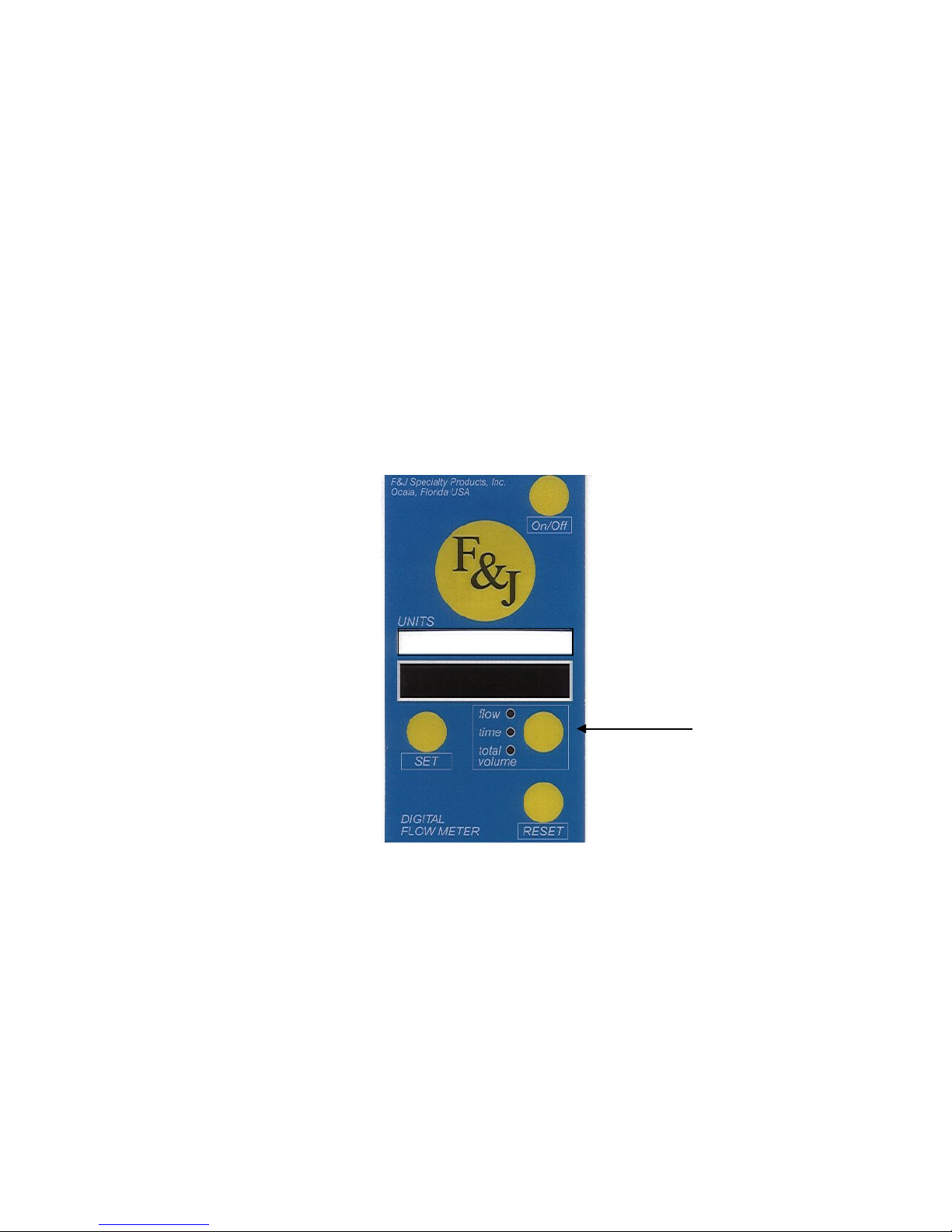
Flow / Volume: SLPM / SL
UNITS
The Digital Flowmeter:
The Digital Flowmeter (DFM) is the control panel of the air sampler. Through the DFM, the operator
activates the features of the instrument, as well as monitor the flow parameters.
The keypad for the DFM series of air samplers has the following features:
1. Four keypad buttons
2. 6 character LED display of 0.5 inch (1.2 cm) height
3. Label indicating the engineering units for the flow represented by the digits
displayed by the LED
These engineering units are factory set and can not be changed in the field.
F:\MARKETING\TECHNICAL MANUALS\Air Samplers\DF Battery TECH MANUALS\DF-75 LPM SERIES.doc
Tel: (352) 680-1177 / Fax: (35 2) 680-1454 / Email: [email protected]
Page 12
12
OPERATING FEATURES and INSTR UCTIONS (Cont.)
Keypad Buttons and Their Functions
ON-OFF: The ON-OFF button is located in the upper right corner of the DFM
module.
Pressing the ON-OFF button while the air sampler is connected to line
power but not running will place the unit in standby mode. Power is
enabled to the DFM.
RESET: The RESET button is located in the lower right hand corner of the DFM
module.
The RESET button is utilized to start and stop the air sampler motor, to
commence a sampling event or to terminate a sampling event, when
manual on/off is enabled.
Note: The DFM must be in flow mode for Reset to function as a pump
On-Off button.
The accumulated elapsed time and accumulated total volume are not
automatically reset to zero when the air sampler is started. This feature
allows the operator to temporarily suspend sampling for maintenance, to
implement a different set up, or to enable different features.
Note: In Time display mode, the RESET button zeros the elapsed time.
In Total Volume display mode, the RESET button zeros total volume.
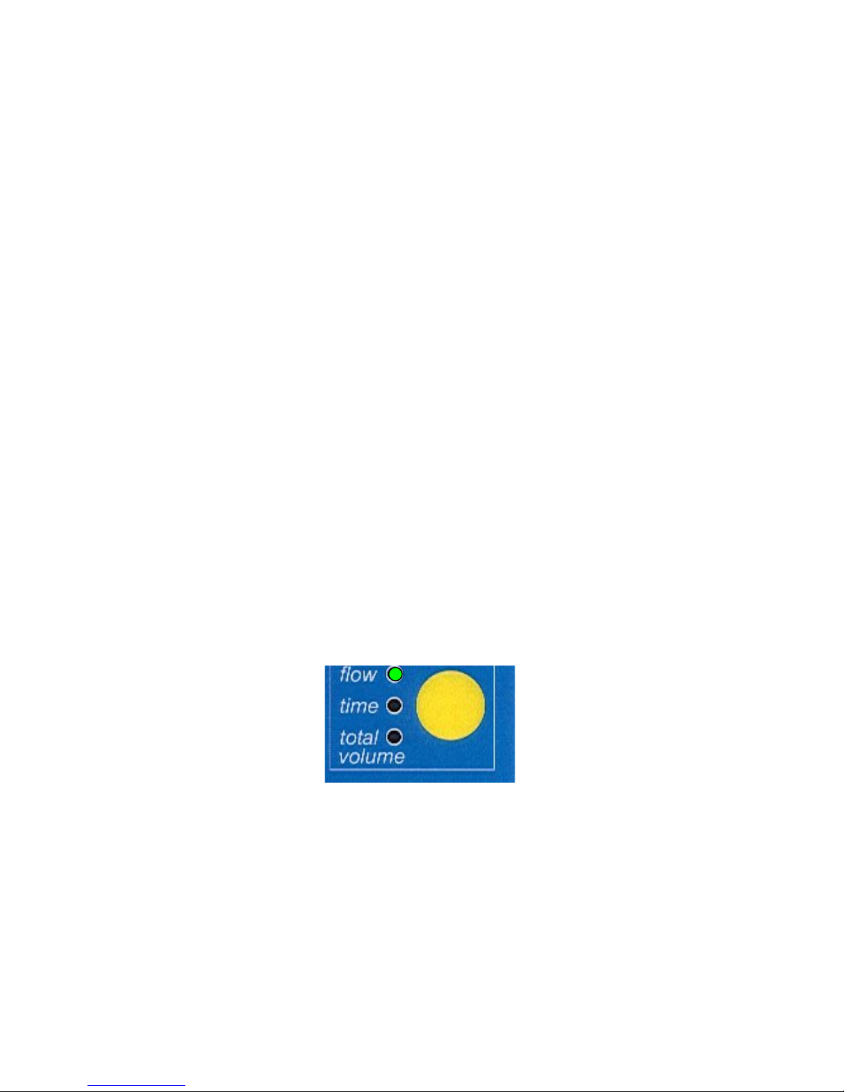
UNITS: The UNITS button is located on the right side of the DFM module.
Pressing the UNITS button enables an operator to display flow, elapsed
time, or total volume by advancing the green LED to the different
positions.
The default position of the green LED is the Flow position upon start up or return to power after a
power outage.
Pressing the UNITS button once moves to the Elapsed Time (time) position displayed
in HHH:MM (Hours-Minutes mode).
Pressing the UNITS button when the green LED is in the time position advances to the
total volume position.
NOTE: Do not assume that total volume and elapsed time are zero when flow is zero.
Check both the elapsed time and total volume values prior to commencing a sample
event.
F:\MARKETING\TECHNICAL MANUALS\Air Samplers\DF Battery TECH MANUALS\DF-75 LPM SERIES.doc
Tel: (352) 680-1177 / Fax: (35 2) 680-1454 / Email: [email protected]
Page 13

13
OPERATING FEATURES and INSTR UCTIONS (Cont.)
In Time display mode, the colon (:) blinks when the motor is turned on and is continuously illuminated
when the air sampler is in stand-by condition. The blinking colon also indicates that the elapsed time
accumulation is in progress.
SET:
Engineering Units
The engineering units for flow and volume are listed on the label above the LED display. The
engineering units, selectable by the user at the time of purchase, are as follows:
Flow Volume
SCFM SCF
SLPM SL
SCMH SCM
sccm scc
A user can not switch engineering units in the field. The Digital Flowmeter electronic unit must be
returned to the factory to change the engineering units and to recalibrate the system sensors.
F:\MARKETING\TECHNICAL MANUALS\Air Samplers\DF Battery TECH MANUALS\DF-75 LPM SERIES.doc
Tel: (352) 680-1177 / Fax: (35 2) 680-1454 / Email: [email protected]
The SET button is located on the left side of the DFM. The SET button is
utilized to set, enable, or disable one or more of the available features
listed below:
Automatic Shut-Off on time
Automatic Shut-Off on volume
Activation of Flow Control
Selection of Data Frequency
Selection of Actual or Standard Flow
Page 14

14
RS232 Communications Port
General
Most models of the Digital Flowmeter have the RS232 communications port enabled.
The DFM transmits a fixed length, comma delimited ASCII string of data. The data string is comprised
of the following parameters in its general format.
dd.hh.mm,ttt.t.F,bb.bb.In Hg, dd.dd In H2O (aaaaaaaaa or ccccccccc), uuuuu,
[….],vvvvvvvvv,UUU
Where:
dd,hh:mm - elapsed time in day.hour: minute format
ttt.t. T - temperature [ºF] or [ºC]
bb.bb. InHg - barometric (inlet) pressure [InHg] or [mm Hg]
dd.dd InH2O - differential pressure [InH2O] or [mm Hg]
aaaaaaaaa - ambient flow with 3, 2 or 1 decimal digit resolution up to
99999, or in x.xxxEyyy format for larger numbers. This
format ensures the possible best resolution even for large
values. Ambient flow has an “a” as prefix
ccccccccc - corrected flow (same format as for the ambient flow) but
it has an “S” prefix
uuuuu - Engineering Unit for flow: SCFM, SLPM, sccm or
SCMH or aCFM, aLPM, accm or aCMH if ambient flow
is selected
[…] - optional values for Totalizer model
vvvvvvvvv - Total volume (same format as for the ambientflow)
UUU - Engineering Unit for total volume: SCF, SL, scc or SCM
or aCFM, aL, acc or aCMH
The engineering units change according to customer selection. The […] data (total flow and
engineering units are sent out when the Totalizer option is enabled.)
An example of a data string utilizing English units is illustrated below.
0.00:21,77.2 F, 30.74 InHg, 2.98 In H2O, 2.72SCFM, 50.21SCF
Data transmission frequency is operator selectable at once per second, once per minute, once per 6
minutes, and once per hour from the serial port.
F:\MARKETING\TECHNICAL MANUALS\Air Samplers\DF Battery TECH MANUALS\DF-75 LPM SERIES.doc
Tel: (352) 680-1177 / Fax: (35 2) 680-1454 / Email: [email protected]
Page 15

15
Serial Data U tilization
Any device that can accept serial data through a communications port can receive the data and store it
automatically as a text string that can ultimately be imported to a spreadsheet or database. The part
number for this Data Storage Device is 232FCDSD. The 1 GB Secure Digital Card part number is
372239, and the PC Flash Card Reader part number is 515177.
F&J has a field instrument that is uniquely designed to accept the serial communications from the
Digital Flowmeter as well as any other instrument that has a serial communications port. Please
request information and specifications on F&J’s Multi-Function Datalogger and Controller (P/N:
MFDC-1).
Actual Flow Feature
A purchaser may select to display actual flow rate and totalized actual volume or flow rate and volume
at one of four factory settable reference temperature and pressure conditions.
For F&J Standard Temperature and Pressure instrumentation, the options for reference T and P
are as follows:
Standard Temperature: 0ºC, 20ºC, 21.1ºC (70ºF) or 25ºC
Standard Pressure: 1 atmosphere (760 mm Hg)
NOTE: F&J does not recommend the installation of the Actual Flow options for sampling
activities of more than 8 hours in duration or if sample volumes or resultant data are
to be compared between different plant locations throughout the state or country.
Re-calibration Frequency
The Digital Flowmeter calibration accuracy should be verified on a once per year frequency absent any
suspected or observed damage to the unit. A factory calibration is recommended at the time of known
or suspected damage to the unit.
Test Mode
The Digital Flowmeter has a test mode that provides the user with calibration data. The following
procedure allows entry into the test mode:
1. With the DFM off, press and hold the UNITS and RESET buttons while pressing the
On-Off button. All LEDs light and the program number appears.
2. When the program number appears, release the UNITS and RESET buttons.
Example: PR XXX. The following information appears in sequence:
• Engineering Units. Example: E.U. SL
(Engineering Units – Standard Liters)
• Venturi or Orifice used for factory calibration. Example: 812 or D812
• Serial Number of the DFM, which should be the same as the serial
number on the air sampler. Example: SN.8062
• Date calibrated. Example: 10.20.04
3. After the above information appears, the DFM displays random digits. This signifies
the end of the test mode. You must turn off the DFM to exit text mode. Press the On-
Off button again to start in normal mode.
F:\MARKETING\TECHNICAL MANUALS\Air Samplers\DF Battery TECH MANUALS\DF-75 LPM SERIES.doc
Tel: (352) 680-1177 / Fax: (35 2) 680-1454 / Email: [email protected]
Page 16

16
Setup Enabled Features
The DFM may have one or more optional features enabled. These features are only enabled at the
factory when the customer purchases the feature.
Note: Because of LED dimming, press the SET button twice to advance to each feature. Pressing the
Set button once brightens the LEDs.
Press On-Off
• Place the DFM in standby mode by pressing the ON-OFF button if the power to
the DFM is not activated. The LEDs are visible in standby mode.
• Press the SET button to advance to the first enabled feature.
Note: If a feature is not enabled, it will not appear in the display.
Automatic Shut-Off on Time Feature
OFFT:
Y or N appears on the display. You have the option to temporarily
disable this feature by pressing the UNITS or RESET button to change
the Y to an N.
The time setting screen displays hhh:mm (hours: minutes). Any time
value can be set from 0:01 to 168:00 hr:min.
1. Set the minutes value first. Press the UNITS button to increase the
minutes value or the RESET button to decrease the minutes value.
2. Press the SET button to move to the hours set-up screen. Press the
UNITS button to increase the hours value or the RESET button to
decrease the hours value.
NOTE: If the hours value has changed pressing the SET button
allows the customer to go back to the minutes setup screen.
3. Press the SET button to move to the next feature.
Automatic Shut-Off on Volume Feature
OFFV:
Y or N appears on the display. You have the option to temporarily
disable this feature by pressing the UNITS or RESET button to change
the Y to an N.
Any volume value can be set from 0.01E00 to 9.99E99
Note: The “V” in the “OFFV” is actually a “U.” This is because of the
segments of the LED display.
NOTE: The automatic shut-off on volume feature generally is not
enabled if the automatic shut-off on time has been enabled. However, it
is physically possible to have both enabled. The shut-off feature that is
most restrictive will occur first and thus terminate the sampling event.
1. Set the exponent value first. Press the UNITS button to increase the
exponent value or the RESET button to decrease the exponent value.
2. Press the SET button to move to the digits set-up screen. Press the
UNITS button to increase the digits value or the RESET button to
decrease the digits value.
NOTE: If digits to the right of the decimal point have changed,
pressing SET takes the customer back to the exponent setup screen.
F:\MARKETING\TECHNICAL MANUALS\Air Samplers\DF Battery TECH MANUALS\DF-75 LPM SERIES.doc
Tel: (352) 680-1177 / Fax: (35 2) 680-1454 / Email: [email protected]
Page 17

17
3. Press the SET button to move to the next feature.
Activation of Flow Control
Fl.C.3 Y or N appears on the display.
(Fl.C.3 for DF-75L-12 and DF-75L-Li)
1. Press the UNITS or RESET buttons to change from Y to N. A Y
enables flow control. An N disables flow control, and the motor runs
at maximum.
2. Press the SET button again to set the flow rate. Use the UNITS
button to increase the flow rate. Use the RESET button to decrease
the flow rate.
3. Press the SET button to move to the next feature.
Selection of Serial Data Freq u en cy Feature
SIO.: 1S, 1m, 6m or 1hr appear s on the display. Press the UNITS or
RESET butto n to change the frequency at which data is to be
sent to a data storage de vice. Press the SET button to advance
to the next fe ature.
Selection of Actual or Standard Flow Feature
Act. F. :
Y or N appears in the display. Press the UNITS or RESET button to
change this value. Selecting a Y provides Actual Flow readings on the
display. Selecting an N provides Standard Flow readings on the display.
Press the SET button to advance to SAVE.
Save the Settings
SAVE:
Y appears on the display if you have made changes to the setup. If no
changes were made, the program returns to the regular display mode.
1. Press the UNITS or RESET buttons to change from Y to N.
2. Press the SET button to save the changes. DONE appears in the
display briefly, then the program returns to the regular display mode.
F:\MARKETING\TECHNICAL MANUALS\Air Samplers\DF Battery TECH MANUALS\DF-75 LPM SERIES.doc
Tel: (352) 680-1177 / Fax: (35 2) 680-1454 / Email: [email protected]
Page 18

18
OPERATING FEATURES and INSTR UCTIONS (Cont.)
Operating Instructions
Starting and Stopping an Air Sample Event
Starting a New Air Sam ple Event
1. If the air sampler is not already on, press the ON-OFF button.
2. Press the UNITS button to view the elapsed time value and total volume
value to ensure that these values are zero.
Note: If these values are not zero, press the RESET button when the
green LED is in the Time position to zero the elapsed time. Press the
RESET button when the green LED is in the Total Volume position to
zero the total volume value.
3. Press the UNITS button to return the green LED to the flow position.
4. If the motor is not running, press the RESET button to start the sample
event.
Temporary S uspension of an Air Sample Event
1. Ensure that the UNITS LED is in the Flow position, then PRESS the
RESET button to shut off the pump motor. The accumulated elapsed
time and accumulated volume up to the time of suspension is saved and
viewable by the operator.
Note: Elapsed time is not counted when the pump motor is off. The
Total Volume value is frozen because Flow is zero when the pump motor
is off.
2. Press the RESET button with the UNITS in the flow mode to resume the
sample event.
Terminatin g an Air S am p le Even t
1. Press the RESET button with the UNITS in the flow mode if the pump is
operating. This turns off the pump motor and preserves the elapsed time
and total volume values.
2. Obtain and record the elapsed time and total volume values.
3. Press the ON-OFF button to turn off the air sampler.
4. Remove the filter(s) from the filter holder for laboratory analysis.
F:\MARKETING\TECHNICAL MANUALS\Air Samplers\DF Battery TECH MANUALS\DF-75 LPM SERIES.doc
Tel: (352) 680-1177 / Fax: (35 2) 680-1454 / Email: [email protected]
Page 19

19
FILTER HOLDERS
The 75 LPM DF Batte ry Seri es Air Sam plers acc epts a st andard F &J plas tic combi nation fi lter hol der.
Filter holders are available for F&J Model B, Model C and Model M radioiodine adsorption cartridges
in combination with either 47mm or 2.0-inch diameter particulate filter paper. The F&J combination
filter holders have dual O-Rings and/or gaskets to ensure that the entire airflow path is through the
filter cartridge and not around it.
Twisting any two of the three separate segments of the filter holder in opposite directions can
disassemble the filter holder. The entire filter holder may be removed from the air sampler by
disengagement of the quick disconnect coupling. Conversely, the filter holder can be installed by
connecting the quick disconnect coupling between the filter holder and pump chassis. Extra filter
holders may be purchased separately.
F&J plastic filter holders available for the Low Volume Series Air Sampler are listed below:
MODEL # DESCRIPTION
FJ-05P Open-face plastic combination; 2.0” particulate – F&J Model B
charcoal cartridge; 3/8” FPT
FJ-21P Open-face plastic combination; 2.0” particulate – F&J Model C
charcoal cartridge; 3/8” FPT
FJ-35P Open-face plastic combination; 47 mm particulate – F&J Model
B charcoal cartridge; 3/8” FPT
FJ-46P Open-face plastic combination; 47 mm particulate – F&J Model
C charcoal cartridge; 3/8” FPT
FJ-51P Open-face plastic combination; 2.0” particulate – F&J Model M
metal can, charcoal cartridge; 3/8” FPT
FJ-53P Open-face plastic combination; 47 mm particulate –F&J Model
M metal can, charcoal cartridge; 3/8” FPT
F&J manufactures filter holders of aluminum and stainless steel to meet specific customer
requirements. Refer to the F&J catalog Filter Holder section for a complete description of the models
currently available from F&J.
F&J can supply customers with various different glass fiber grades of filter paper or cellulose grades of
filter paper. Consult F&J about the optimum filter paper to utilize for your application.
F:\MARKETING\TECHNICAL MANUALS\Air Samplers\DF Battery TECH MANUALS\DF-75 LPM SERIES.doc
Tel: (352) 680-1177 / Fax: (35 2) 680-1454 / Email: [email protected]
FILTER PAPER
Page 20

20
SENSORS
FLOW SENSOR:
The Digital Flowmeter Battery Series Air Samplers com equipped with a precision-machined
differential pressure sensor. The relationship of the differential pressure across the sensor as a function
of flowrate is stored in the microprocessor and utilized as the starting value to determine the flowrate
and totalized volume corrected to a reference temperature and pressure. The purchaser selects the
conditions at the time of purchase. Four choices are available.
TEMPERATURE SENSOR:
A thermistor temperature sensor is placed in-line in the air stream at the entrance to the venturi to
accurately measure the temperature of the air that is flowing through the flow sensor. The accuracy of
the temperature sensor is +/- 0.9ºF (0.5ºC).
DIFFERENTIAL PRESSURE SENSOR:
A precision electronic differential pressure sensor measures the differential pressure acros s the f lo w
sensor. The total system accuracy of the digital flowmeter air sampler flow sensor and the differential
sensor electronics is accurate to ± 4%.
The electronic diff erential pressure sensor offs et value is automatically calibrated once per minute to
eliminate sensor drift problems. Once per minute the electronic value correlating to a differential
pressure of 0.00 inches of water is measured and stored in the on board computer. This ensures that all
flow rate determinations for flow rate are unaffected by sensor electronic drift. This is especially
important for low differential pressure measurements.
PRESSURE SENSOR:
A precision pressure sensor accurately measures the absolute pressure at the inlet of the flow sensor to
± 1% over the measured range.
The sensors are calibrated across the range of approximately 22 inches to 29.92 inches of mercury.
This corresponds to an approximate range of 7000 feet elevation down to sea level. The reference
value for pressure correction has been chosen to be 1 atmosphere of pressure (29.92” Hg). A custom
reference for unique customer requirements is available as an option for a fee.
F:\MARKETING\TECHNICAL MANUALS\Air Samplers\DF Battery TECH MANUALS\DF-75 LPM SERIES.doc
Tel: (352) 680-1177 / Fax: (35 2) 680-1454 / Email: [email protected]
Page 21

21
CORRECTIONS TO A REFERENCE TEM P E RATURE
AND PRESSURE
FLOW RATES:
The differential pressure measurements of the differential flow sensor as a function of flow rate are
determined during the calibration process and stored in the system microprocessor.
The calculated flow rate value at the pressure and temperature conditions of the field flow
measurements (often referred to as actual flow) is determined and subsequently corrected to a
reference temperature and pressure condition that has been set at the factory.
One atmosphere pressure is the default reference pressure.
The equation utilized to correct the flow at field conditions to a reference T and P is as follows:
Flow (REF) = Flow (Actu al) • T REF • P ACTUAL
T ACT 29.92: Hg (760mm Hg)
Reference temperature options that are factory settable are 0ºC, 20ºC, 70ºF and 25ºC.
Definitions of different reference T and P conditions
Classical STP 0Cº, 1 Atm
Normal T and P 20ºC, 1 Atm
Modified Normal T and P 21.1ºC (70ºF), 1 Atm
Standard Ambient T and P 25ºC, 1 Atm
TOTALIZED SAMPLE VOLUME:
Totalized sample volume values are corrected to standard temperature and pressure also. Totalized
volume is calculated by adding up the incremental volume calculations stored in the memory for the
collection period frequency. The incremental corrected volume is calculated from the formula.
V incremental = Flow Rate (Corrected) × Time Interval
Totalized Volume n
V (Incremental) i
i = 1
F:\MARKETING\TECHNICAL MANUALS\Air Samplers\DF Battery TECH MANUALS\DF-75 LPM SERIES.doc
Tel: (352) 680-1177 / Fax: (35 2) 680-1454 / Email: [email protected]
Page 22
22
F&J SPECIALTY PRODUCTS, INC.
The Nucleus of Quality Air Monitoring Programs
Low Voltage Limiting System Description
The F&J battery powered air sampler has a battery low voltage
limiting system installed, which will prevent complete
discharge of the battery.
The low voltage limiting circuitry promotes longer battery life
and increases the number of charging cycles.
This low voltage limiting circuitry is factory-preset. Once the
battery voltage reaches the factory-preset level, the instrument
will shut down and go into a safe mode. An operator will still
be able to retrieve the elapsed time and accumulated volume
data to the time of shut down.
The operating time on a single charge cycle will primarily
depend on the motor amperage draw.
Higher flow rates and filter media with greater airflow
resistance will effectively increase amperage draw and thus
shorten the operating run time of the air sampler.
Factory Preset Low Voltage Values
1) Lithium ion Battery: 12V
2) Lead Acid Battery: 10.5V
F:\MARKETING\TECHNICAL MANUALS\Air Samplers\DF Battery TECH MANUALS\DF-75 LPM SERIES.doc
Tel: (352) 680-1177 / Fax: (35 2) 680-1454 / Email: [email protected]
Page 23
23
CALIBRATION VERIFICATION INSTRUCTIONS
General
The calibration of 75 LPM DF Battery Series air samplers should be verified periodically. Good air
monitoring practice guidelines recommend a minimum of at least once per year calibration frequency.
A calibration verification should be made immediately after each repair involving the Digital
Flowmeter, or the motor. Additionally, a calibration verification should be performed at any time there
is a suspicion of erroneous readings or if a different filter media is utilized than that upon which th e air
sampler was originally calibrated.
A flow calibration instrument having an accuracy of ± 1% of full scale or better is recommended for
the calibration verification.
The calibration verification procedure involves the comparison of the flow value displayed on the
Digital Flowmeter Air Samplers to the flow value displayed on the reference calibrator. The filter
media to be utilized during sampling should also be utilized during the calibration process.
F&J recommends the utilization of either its CD-812-1 (110VAC) or CD-812E-1 (230VAC) 1%
accuracy Digital Ai rflow Calibrator as the refe rence flow device for the DF-75L-12 and DF-75L-Li.
The Compact Digital Calibrator has a moveable flow sensor to facilitate calibration in the field.
Connecting the calibrator to the Air Sampler:
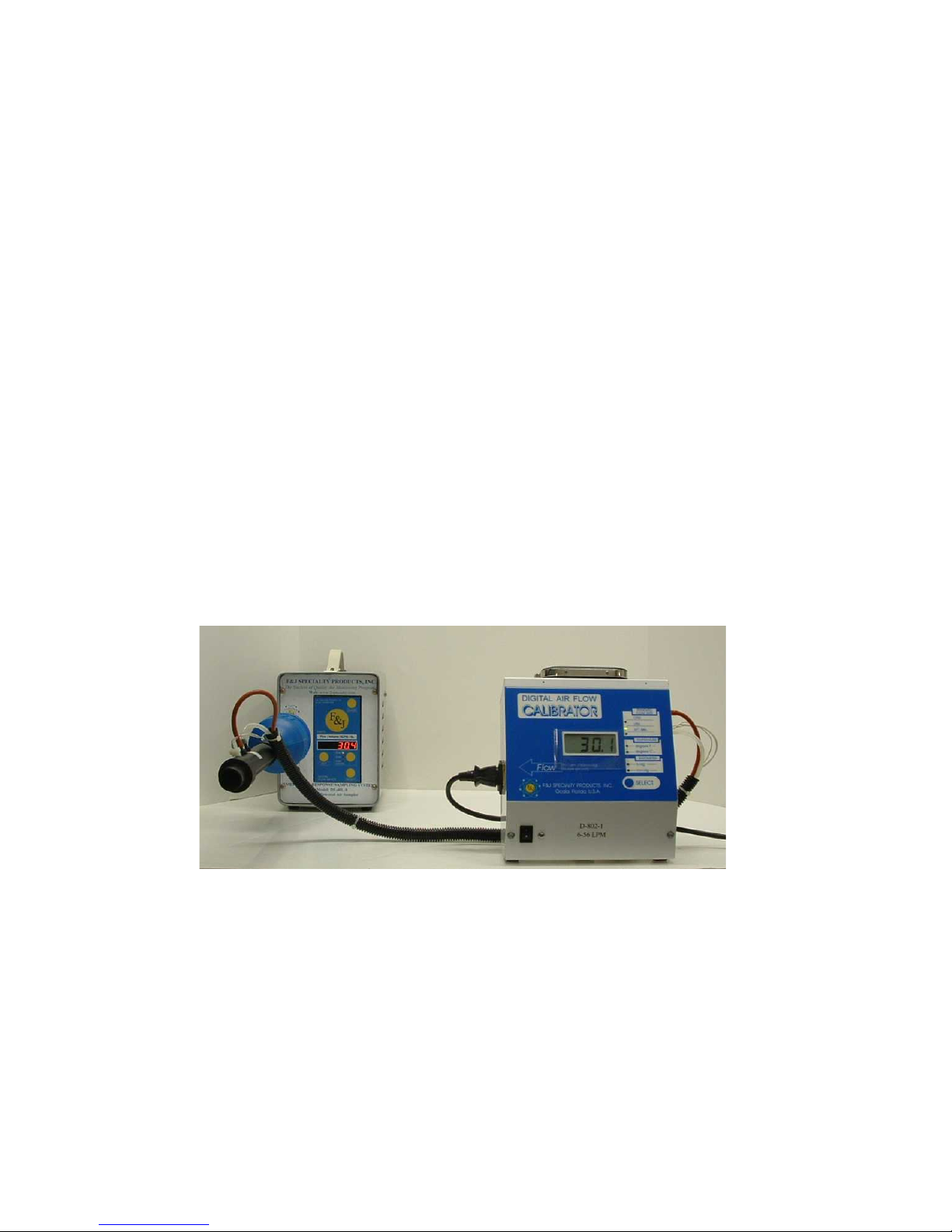
To perform the cal ibration ver ification, ad aptors are need ed to interf ace the reference calibrator t o the
air sampler inlet. For the DF Battery Series Air Samplers, the adaptor is mounted to the particulate
section of the filter holder and onto the flow output of the calibrator, as illustrated in Figure 5 below.
Figure 5 Calibration
Note: Be sure to insert the proper filter media into the air sampler filter holder prior to
attaching the adaptor to the air sampler.
F:\MARKETING\TECHNICAL MANUALS\Air Samplers\DF Battery TECH MANUALS\DF-75 LPM SERIES.doc
Tel: (352) 680-1177 / Fax: (35 2) 680-1454 / Email: [email protected]
Page 24

24
CALIBRATION INSTRUCTI ONS
The adaptor secures to the air sampler with a quick connect fitting and to the calibrator with the
attached tubing. During the verification, the adaptor replaces the filter holder.
NOTE: Be sure to insert the proper filter media into the air sampler adaptor prior to attaching
the adaptor to the air sampler.
Performing the Calibration:
Ensure the air sampler and the calibrator are on a level surface
Ensure the Calibrator has warmed up at least 10 minutes
Confirm the filter paper in the air sampler is the same filter paper to be utilized for the
sampling activity.
1. The Digital Flow Meter Series Air Sampler indicates flow rate at a reference T
and P. The F&J Digital Calibrator also displays flow rate at a reference
temperature and pressure. Therefore, a direct comparison can be made between
them if the reference T and P are the same for the calibrator and the air sampler.
2. Set the calibrator to display the same engineering units that the air sampler is
reading (CFM or LPM). Confirm that the filter paper is installed and that there
isn’t air leakage in the system.
3. Start the air sampler and adjust to sample at or near maximum flow. Allow the
flow to stabilize prior to documenting the comparison of flows. This
stabilization period may take three to four minutes. Allow both the calibrator
and the air sampler to operate approximately 10 minutes prior to commencing
step No. 4 below.
4. Compare the flow rate on the calibrator with the reading on the air sampler and
record this information on the calibration data sheet (the following page). It may
be necessary to average the readings over a 15-20 second period if there are
fluctuations in the flow rate value.
5. Repeat the same process for three other air sampler flow rates whose range is in
the area of interest for sampling. This step is not necessary if you always sample
at a specific flow rate.
6. Compute the deviations and the % deviations for each of the readings and record
on the calibration data sheet.
7. Sign and date the data sheet.
8. Investigate any unacceptable deviations between the calibrator and the air
sampler.
Note that air leakage is the most probable cause for large deviations between the
air sampler and the calibrator.
F:\MARKETING\TECHNICAL MANUALS\Air Samplers\DF Battery TECH MANUALS\DF-75 LPM SERIES.doc
Tel: (352) 680-1177 / Fax: (35 2) 680-1454 / Email: [email protected]
Page 25

25
Digital Flow Meter Series
Calibration Verification Procedure Data Sheet
% of Deviation Full Scale = (3) × 100
Record refe rence values (2) and Air Sampler values (1) in same units
Digital Flow Meter Low Volume Series Acceptable Deviation = 4.0% of Full Scale
Full Scale Accuracy Value for various models covered by this operator manual are as follows:
DF-75L-Li = ± 3 SLPM
DF-75L-AC = ± 3 SLPM
NOTE: The reference T and P of the reference calibrator and the device under tes t s hould be the same,
otherwise one instrum ent’s display value for flow must be corrected to the same r eference T and P
conditions of the other instrument.
(REF) flow (REF) flow F.S.
(1) (2) (3) (4)
DF Air Sampler Reference Calibrator Deviation % of Deviation
CCM, CFM , LPM or CMH CCM, CFM, LPM or CMH
Flow Rate 1 ______________ _________________ ____________ _________
F:\MARKETING\TECHNICAL MANUALS\Air Samplers\DF Battery TECH MANUALS\DF-75 LPM SERIES.doc
Tel: (352) 680-1177 / Fax: (35 2) 680-1454 / Email: [email protected]
Flow Rate 2 ______________ _________________ ____________ _________
Flow Rate 3 ______________ _________________ ____________ _________
Flow Rate 4 ______________ _________________ ____________ _________
Deviation (3) = R eference Ca librator Value (2) – Air Sampler value (1)
Full Scale Accuracy Value
Page 26
26
WARNING
CAUTION
MAINTENANCE INSTRUCT IONS
PRIOR TO PERFORMING ANY MAINTENANCE, DISCONNECT THE
AIR SAMPLER CORD FROM THE POWER SOURCE.
DISASSEMBLY or ATTEMPTED REPAIRS:
If accomplished incorrectly, repairs can create an electrical shock hazard. It is
recommended that repairs be made by a qualified electrician or technician or be returned
to F&J SPECIALTY PRODUCTS, INC.
REMOVE THE FRONT PLATE
1. Unplug the air sampler from the power source.
2. Remove the filter holder and quick disconnect from the air sampler.
3. Remove the (4) four sheet metal screws from the front plate of the air sampler.
4. Carefully, move the front plate (with DFM and Battery Gauge Indicator) away from the front of the
instrument.
5. Disconnect all the electric and sensor connections to the DFM and Battery Gauge Indicator. Refer
to the spare parts list and electrical diagram on the following pages. These connections are for the
following:
• Pump/Motor
• 12VDC
• RS232 to optional Datalogger
• Temperature Sensor
• Differential Pressure Sensors
• Battery Gauge Indicator
6. Set the front plate with DFM aside.
7. Remove the (2) two screws from the left side of the instrument. These screws hold the orifice tube
in place. Pull the orifice tube straight out through the front of the air sampler.
8. If you are sending the DFM back to F&J, you must send the orifice tube with temperature sensor
and the DFM. These items are serviced and calibrated as a complete set.
9. With the front plate out of the way, you can now get to the following parts:motor, battery, and
power supply.
• Pump
• Battery Charger Circuit
• Power supply
• Battery
10. After you make necessary repairs, replace the orifice and front plate by performing the above steps
in reverse order.
F:\MARKETING\TECHNICAL MANUALS\Air Samplers\DF Battery TECH MANUALS\DF-75 LPM SERIES.doc
Tel: (352) 680-1177 / Fax: (35 2) 680-1454 / Email: [email protected]
Page 27

27
DF-75L-Li Series Parts List
Part Number
Description
Part Number
Description
QD38FMR
Quick Disconnect
DF-VTH
Orifice Tube Holder
STIK5023
Rubber Feet
H2085
Handle
75LPMPUMP
75 LPM Pump
4C-175(156)15-
CP144-1
2.60”D Diaphragm
ELECTRICAL PARTS
Part Number
Description
Part Number
110-120VAC; 50/60Hz
220-240VAC; 50/60Hz
LIP-18650
Lithium ion Battery 15.6 Ah
LIP-18650
F3AMP
Fuse; 3 Amp
F3AMP
310005
12 VDC Motor, 60 Watts
310005
310006
18 VDC Motor; 60 Watts
310006
AN37105
AC Power Cord
AN37106
CEINF
AC Socket/Line Filter
CEINF
LVDFMVHCV.2
Digital Flowmeter, 60 Watt
LVDFMVHCV.2
BATCHGG4
Battery Charger Circuit
BATCHGG4
BATIND3
Battery Gauge Indicator
BATIND3
GTPS107
Power Supply, 20V/4.5A
GTPS107
OPTIONS
Part Number
Description
Part Number
232FCDSD
Data Storage Device
232FCDSD
372239
2+ GB Secure Digital Card
372239
SDDR-199-A20
PC Flash Card Reader
SDDR-199-A20
CD-812V.2-1
Compact Digital Calibrator;
1% accuracy, 15-115 LPM
CD-812EV.2-1
F:\MARKETING\TECHNICAL MANUALS\Air Samplers\DF Battery TECH MANUALS\DF-75 LPM SERIES.doc
Tel: (352) 680-1177 / Fax: (35 2) 680-1454 / Email: [email protected]
Page 28

28
DF-75L-AC Series Parts List
Part Number
Description
Part Number
Description
QD38FMR
Quick Disconnect
DF-VTH
Orifice Tube Holder
STIK5023
Rubber Feet
H2085
Handle
75LPMPUMP
75 LPM Pump
4C-175(156)15-
CP144-1
2.60”D Diaphragm
HB3812
Exhaust Port Hose Barb
HB3838
Intake Port Hose Barb
ELECTRICAL PARTS
Part Number
Description
Part Number
110-120VAC; 50/60Hz
220-240VAC; 50/60Hz
F3AMP
Fuse; 3 Amp
F3AMP
310005
12 VDC Motor, 60 Watts
310005
310006
18 VDC Motor; 60 Watts
310006
AN37105
AC Power Cord
AN37106
CEINF
AC Socket/Line Filter
CEINF
LVDFMFVHCV.2
Digital Flowmeter, 15-115 LPM
LVDFMFVHCV.2
GTPS108
Power Supply, 12V/6.6A
GTPS107
OPTIONS
Part Number
Description
Part Number
232FCDSD
Data Storage Device
232FCDSD
372239
2+ GB Secure Digital Card
372239
SDDR-199-A20
PC Flash Card Reader
SDDDR-199-A20
CD-812V.2-1
Compact Digital Calibrator;
1% accuracy, 15-115 LPM
CD-812EV.2-1
F:\MARKETING\TECHNICAL MANUALS\Air Samplers\DF Battery TECH MANUALS\DF-75 LPM SERIES.doc
Tel: (352) 680-1177 / Fax: (35 2) 680-1454 / Email: [email protected]
Page 29
29
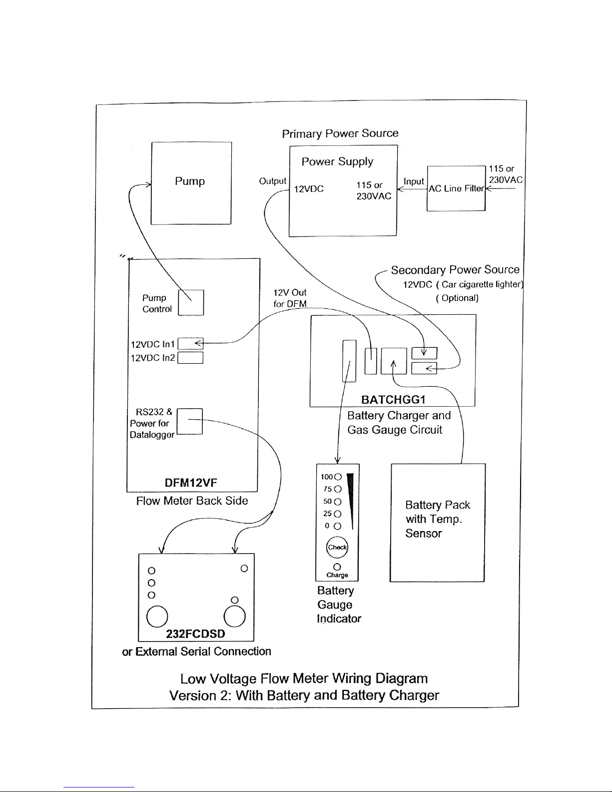
ELECTRICAL WIRING DIAG RAM for
DF-75L-Li
F:\MARKETING\TECHNICAL MANUALS\Air Samplers\DF Battery TECH MANUALS\DF-75 LPM SERIES.doc
Tel: (352) 680-1177 / Fax: (35 2) 680-1454 / Email: [email protected]
Page 30
30
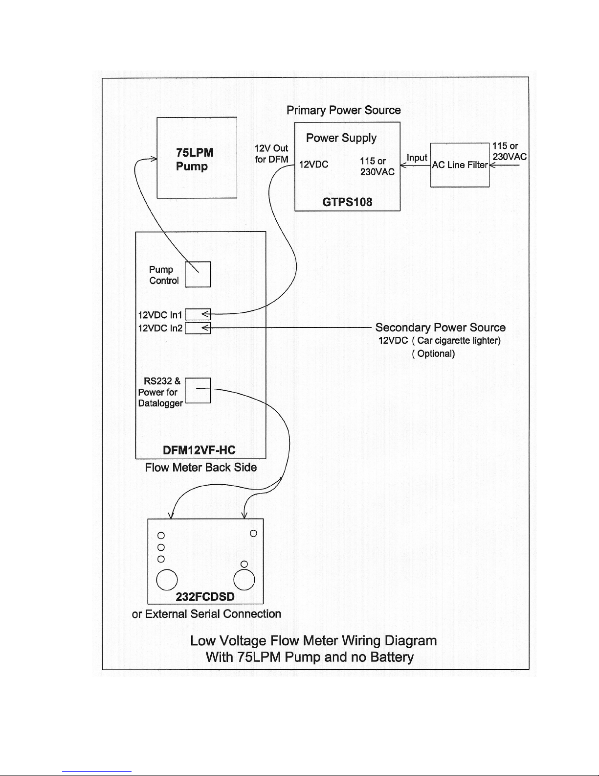
ELECTRICAL WIRING DIAG RAM for
DF-75L-AC
F:\MARKETING\TECHNICAL MANUALS\Air Samplers\DF Battery TECH MANUALS\DF-75 LPM SERIES.doc
Tel: (352) 680-1177 / Fax: (35 2) 680-1454 / Email: [email protected]
Page 31

31
WARRANTY
Limited Warranty: The Seller represents and warrants to the Purchaser that any equipment
manufactured by Seller and bearing Seller’s name plate to be free from defects in material or
workmanship, under proper and normal use and service, as follows: if, at any time within 1 year from
the date of sale, the S eller recei ves writt en not ificati on from Purch aser, th at i n Purchas er’s opi nion, the
equipment is defective and returns the equipment to the Seller’s originating factor y prepaid and the
Seller’s inspection finds the equipment to be defective in material or workmanship, the Seller will
promptly correct it by either, at Seller’s option, repairing any defective part or material or replacing it
free of charge and return shipped lowest cost transportation prepaid. (If Purchaser requests premium
transportation, Purchaser will be billed for transportation costs.) If inspection by the Seller does not
disclose any defect in material or wor kmanship, the Sel ler’s regular char ges for repair or rep lacement
will apply. An y replacement or repair will be warranted for the rem ainder of the origin al warranty or
thirty (30) days, whichever is longer.
Sole Remedy: S eller’s entire liability and Purchaser’s exclusive remedy shall be limited to the repair or
the replacement of materials or parts as herein described.
Limitations: Notwithstanding the warranty provisions set forth herein, this warranty shall be effecti ve
only if installation, use and maintenance is in accordance with Seller’s instructions and written notice
of a defect is received by the Seller within the period herein provided. Seller shall have no warranty
obligations with respect to any failures of the equipment which are the result of accident, abuse,
misapplication, extreme power surge or extreme electromagnetic field.
Disclaimer of Warranties: This warranty is th e sol e and ex clus ive w arran t y offered b y Seller and i s in
lieu of any other warranties written, oral or implied; specifically without limitation, there is no
warranty of merchantability or fitness for any purpose, even if Purchaser has been informed of such
purpose.
LIMITATION OF LIABILITY
The Seller shall not be liable for an y claim for consequential or incidental loss or damage arising or
alleged to have risen from any delay in delivery, malfunction, failure of the equipment or Seller’s
inability to provide maintenance services for hardware or software related to the products.
Accordingly, Purch aser agrees that Sell er shall not be responsi ble to Purchaser for an y loss-of-profit,
indirect, incidental special or consequential damages arising out of the use of products or services. The
Seller’s liability for any other loss or damage arising out of or connected with the manufacture, sale or
use of the equipment sold or service provided in a maintenance service contract, including liability
that arises from any claim based on breach or repudiation of contract, warranty, tort, or otherwise, shall
not in any event ex ceed the price of the equip ment or services suppli ed by Seller. Seller res erves the
right make changes, at any time without notice, in prices, colors, materials, specifications and models;
and to discontinue models.
F:\MARKETING\TECHNICAL MANUALS\Air Samplers\DF Battery TECH MANUALS\DF-75 LPM SERIES.doc
Tel: (352) 680-1177 / Fax: (35 2) 680-1454 / Email: [email protected]
Page 32

32
SERVICE INFORMATIO N
Technical Assistance:
(352) 6580-1177 / (352) 680-1178
Fax:
(352) 680-1454
Email:
Web Site:
www.fjspecialty.com
Hours:
Monday – Friday
8:00 AM to 4:30 PM (EST)
For all work not covered under warranty, F&J SPECIALTY PRODUCTS, INC. will repair any
instrument for the cost of parts and labor as quoted. If major components must be replaced, F&J
SPECIALTY PRODUCTS, INC. will notify the customer before proceeding with repairs. When
returning any in strument for service, please include a Purchas e Order marked: “Rep air – Cost not to
exceed $250.00 without customer authorization”. Please provide the following information with your
instrument:
Address:
Telephone:
Fax:
Contact Name:
Serial Number(s):
Date of Purchase:
Service Required or Description of Problem:
You must first obtain an RMA number prior to returning any product. Obtain your RMA number by
calling F&J SPECIALTY PRODUCTS , INC. (352) 680-1177 or (352) 680-1178. To expedite service
and repairs, have your Business Name and/or Customer Number handy.
Please ensure that all products returned to F&J contain no hazardous materials. Any obviously
contaminated product received will be returned to the customer. All products scheduled for service
must be received within 30 days of the RMA number issuance date. Unauthorized products will be
returned to the customer.
Company Name:
TECHNICAL SUPPORT SERVICES
If you need additional information or help during installation or normal use of this product, contact
F&J SPECIALTY PRODUCTS, INC. Technical Support. Our customer support staff will attempt to
answer your installation questions by phone or issue a service authorization number for repair or
replacement of your product. Unauthorized returns will not be accepted. When calling for support,
please have your product serial number and product model available.
Shipping Address: F&J SPECIALTY PRODUCTS, INC.
404 Cypress Road
Ocala, Florida 344 7 2
USA
F:\MARKETING\TECHNICAL MANUALS\Air Samplers\DF Battery TECH MANUALS\DF-75 LPM SERIES.doc
Tel: (352) 680-1177 / Fax: (35 2) 680-1454 / Email: [email protected]
Page 33
33
Fast & Friendly Customer Service
Ordering by phone
(352) 680-1177 / 680 -1178
Ordering by Fax
(352) 680-1454
For your convenience
MasterCard, Visa & American Expr ess
Technical Assistance
(352) 680-1177
F:\MARKETING\TECHNICAL MANUALS\Air Samplers\DF Battery TECH MANUALS\DF-75 LPM SERIES.doc
Tel: (352) 680-1177 / Fax: (35 2) 680-1454 / Email: [email protected]
 Loading...