

Five Two One Compressor Saver User Manual

Old Wiring?
TV Screen Flip Flop?
Circuit Breakers Trip?
Low Voltage Situation?
Compressor Hard to Start?
A/C Unit More Than 5 Years Old?
Computers Restart On Their Own?
Lights Dim When the A/C Comes On?
Starting up is the hardest time in the life of any type of electrical equipment. Ever notice that light bulbs
almost always burn out when you first turn them on and not while they are on? This is due to the huge
current that rushes in whenever a switch is thrown and power is first applied.
The compressor on your Air Conditioner consumes more power on start up than any other device in your
home. A compressor may consume 45,000 watts of power while the motor is trying to start-TEN times
more power than it uses while running. In-rush current can damage the compressor’s motor and that
motor may start up more than 10,000 times in a single cooling season.
A 5-2-1®COMPRESSOR SAVER®significantly reduces the amount of time your compressor is on start-up
overload. Most top-of-the-line A/C units come from the factory with 5-2-1®technology built in. Now you
can have a 5-2-1®installed in your A/C unit by a professional.
The 5-2-1®uses a powerful multi-layer starting capacitor and a smart switch to give your compressor the
boost it needs to start up quickly, more reliably, draw less power and save you money too.
The cost of a 5-2-1®is a fraction of the cost of replacing a compressor
damaged by hard starts. It could add years to the life of your compressor.
Ask your A/C technician about a special offer on a 5-2-1®installation!
Scan our QR codes to view videos and learn more about the
5-2-1®COMPRESSOR SAVER®.
atch How It W
W
orks
GENERAL SAFETY INSTRUCTIONS
RUN
CAPACITOR
START
C
T1
CONTACTOR
T2
CONTACTOR
R
S
START
CAPACITOR
POTENTIAL
RELAY
52
1
BLACK
RED
UP
STRIPEDSTRIPED
DUAL RUN CAPACITOR
RED
HERM
FAN
C
STRIPEDSTRIPED
Only trained and qualified service personnel should install this kit. Most states, countries etc. may
require the installer to be licensed. Please check with your local government agency.
DANGER - ELECTRICAL SHOCK HAZARD - always disconnect the power source before
attempting to install this kit. Failure to do so may result in severe electrical injury or even death.
CAUTION - EQUIPMENT DAMAGE - Failure to properly install this kit can and will
cause permanent damage to the compressor and related components.
1) Disconnect all sources of power to the unit. Note that there may be more than one.
2) Locate and remove the electrical service access door or panel.
3) Mount the 5-2-1®Kit potential relay and start capacitor in a suitable location within the
electrical box. The potential relay should be mounted with the mounting tab up. The capacitor
should be mounted with the terminals up. Take care to mount the components so that all
non-insulated live terminals are at least 1⁄2" away from all metal or electrical conducting parts
or components. Mount in a location that will prevent water from coming in contact with the
non-insulated live contacts.
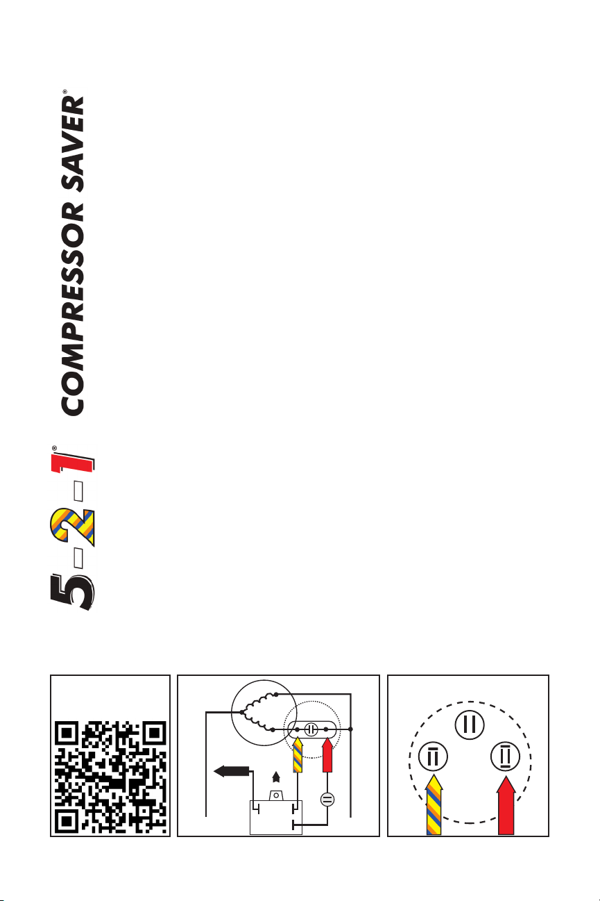
NOTE – The 5-2-1®Compressor Saver®has been pre-wired for your convenience. There are only
3 color coded wires which need to be connected. The Black wire will be connected to the Common
side of the compressor. The Striped wire will be connected to the Start winding of the
compressor and the Red wire will be connected to the Run winding of the compressor.
Remember – 5, 2, 1, = Common, Start, Run. Proceed as follows:
5) Common - Connect the loose end of the Black wire to T1 of the contactor. Check to see that
the Common “C” terminal of the compressor also connects to T1. In most cases you will find
a Black wire coming from the Common “C” terminal of the compressor.
View Our Technical
Installation Video
2) Start - Connect the loose end of the Striped wire to the Start winding side of the run
capacitor. The Start winding side of the run capacitor is always marked “HERM”. The Start
winding side of the run capacitor can also be verified by following the yellow or orange or blue
wire (in most cases) from the compressor “S” terminal to the Start winding side of the run
capacitor.
1) Run - Connect the loose end of the Red wire to the Run winding side of the compressor.
The Run winding is connected to T2 of the contactor as well as the common side of the run
capacitor which is usually marked with a “C” or “=”. The Run winding can be identified in most
cases by a Red wire coming from the R terminal on the compressor. The Red wire from the
5-2-1®start kit is normally connected at the “C” or “=” terminal on the run capacitor, but can
also be connected to T2 of the contactor. View the illustrations below and scan our QR
codes to learn more about the 5-2-1®COMPRESSOR SAVER®.
# IS Rev D
 Loading...