

Page 1

SBU Systems
User Manual
Fivemere Ltd.
Unit 1, Heron Industrial Estate
Basingstoke Road
Spencers Wood
Reading, Berks, RG7 1PJ
United Kingdom
Telephone: [44] (0) 118 988 0082
Fax: [44] (0) 118 988 0081
Page 2

SBU Systems
User Manual
80-30200000-03ii
Publication — 80-30200000-03
Publication Notice:
This manual has been compil ed and c hec k ed for acc ur ac y . However the
information contained in this manual does not constitut e a warranty of
performance. Fivemere Limited reserves the right to revise this
publicat ion from tim e to tim e without not ice. F iv em ere Lim it ed assumes
no liability for losses incurred as a result of out-of-date or incorrect
information contained in this manual.
Proprietary Notice:
©1996-1999, Fivemere Ltd, all rights reserved.
This document may not in whole or part be copied, photocopied,
reproduced, transl ated, or reduced to any electronic medium or machi nereadable form without prior consent from Fivemere Limited.
EMC Directive:
This product has been designed for use in Commercial and Light
Industrial environment s and tested to relevant EMC Standards as listed
in the European O.J. All testing was carried out using screened
interconnection cables. Should the equipment be used in a different
environment the user may need to take additional EMC precautions.
Fivemere Ltd. is a subsidiary of Cabletron Systems Inc., USA.
Page 3

SBU Systems
User Manual
80-30200000-03 iii
History Sheet
80-30200000-01 First Edition March 1996
80-30200000-02 Cabletron Systems Ltd 29 April 1997
80-30200000-03 Fivemere Ltd version,
SBULSM section added
19 October 1999
Page 4

SBU Systems
User Manual
80-30200000-03iv
TABLE OF CONTENTS
1. SCOPE AND INTRODUCTION 1-1
1.1 S
COPE
1-1
1.2 I
NTRODUCTION
1-1
1.3 T
HE
SBU14C 1-2
1.4 T
HE
SBU6C 1-3
2. INSTALLATION AND CABLING 2-1
2.1 M
AINS INPUT AND WIRING
2-1
2.2 S
UPPLY RATINGS AND FUSING
2-3
2.2.1 SBU14C 2-3
2.2.2 SBU6C 2-4
2.3 P
OWER SUPPLY CAPACITIES/REDUNDANCY
2-5
2.3.1 SBU14C 2-5
2.3.2 SBU6C 2-6
3. OVERVIEW OF SHELF MODULES 3-1
3.1 P
OWER SUPPLIES
3-1
3.1.1 SBU14C 3-1
3.1.2 SBU6C 3-1
3.2 C
OOLING
3-2
3.2.1 SBU14C 3-2
3.2.2 SBU6C 3-2
3.3 G
ENERIC SHELF MANAGER MODULE
(SBUGSM) 3-2
3.4 LAN S
HELF MANAGER MODULE
(SBULSM) 3-2
3.5 G
ENERIC PORT SHARER MODULE
(SBUGPS) 3-2
4. GENERIC SHELF MANAGER MODULE 4-1
4.1 O
VERVIEW
4-1
4.2 S
HELF POWER LOADING
4-2
4.3 C
OMMAND ACCESS TO THE
SBUGSM 4-3
4.3.1 P
OLL ADDRESSES AND ALERT FORMAT
4-3
4.3.2 F
ACTORY DEFAULT
4-5
4.3.3 P
ASSWORD ENTRY
4-5
4.4 I
NTERFACES
4-5
4.5 O
PERATION MENU
(A) 4-6
4.6 C
ONFIGURATION MENU
(B) 4-6
4.6.1 S
YSTEM MENU
4-6
Page 5

SBU Systems
User Manual
80-30200000-03 v
4.6.2
COMMAND PORT MENU
4-7
4.6.3 A
LARM PORT MENU
4-8
4.6.4 A
LARMS MENU
4-9
4.7 L
OGOUT
(C) 4-9
5. LAN SHELF MANAGER MODULE 5-1
5.1 O
VERVIEW
5-1
5.2 S
HELF POWER LOADING
5-3
5.3 C
OMMAND ACCESS TO THE
SBULSM 5-3
5.3.1 P
OLL ADDRESSES AND ALERT FORMAT
5-3
5.3.2 IP A
DDRESS
5-5
5.3.3 F
ACTORY DEFAULT
5-5
5.3.4 P
ASSWORD ENTRY
5-5
5.4 I
NTERFACES
5-5
5.5 O
PERATION MENU
(A) 5-6
5.6 C
ONFIGURATION MENU
(B) 5-6
5.6.1 S
YSTEM MENU
5-7
5.6.2 C
OMMAND PORT MENU
5-7
5.6.3 A
LARM PORT MENU
5-9
5.6.4 A
LARMS MENU
5-10
5.6.5 R
EMOTE PORT MENU
5-11
5.6.6 N
UMBER STORE MENU
5-11
5.6.7 LAN
MENU
5-11
5.7 L
OGOUT
(C) 5-14
6. GENERIC PORT SHARER 6-1
6.1 P
HYSICAL REQUIREMENTS
6-1
6.2 P
ANEL LAYOUTS
6-1
6.3 S
HELF POWER LOADING
6-3
6.4 F
UNCTIONAL DESCRIPTION
6-3
6.5 P
HYSICAL INTERFACE
6-3
6.6 C
ARD JUMPERS
6-4
7. SHELF SPECIFICATIONS 7-1
7.1 SBU14C 7-1
7.2 SBU6C 7-2
8. CABLING DIAGRAMS 8-1
8.1 PC 9 W
AY TO
SBUGSM/SBULSM 8-1
8.2 PC 25 W
AY TO
SBUGSM/SBULSM 8-2
Page 6

SBU Systems
User Manual
80-30200000-03vi
8.3
PC 25 W
AY TO
SBUGPS M
ASTER PORT
8-2
8.4 SBUGPS C
HANNEL TO
SBUGSM/SBULSM 8-3
8.5 PC 9 W
AY TO
SBUGPS M
ASTER
8-3
9. GLOSSARY OF TERMS 9-1
Page 7

Scope and Introduction
80-30200000-03 1-1
1. Scope and Introduction
1.1 Scope
This manual prov ides user information for both the Fivem ere SBU14C
and the SBU6C. Although there is indeed no act ual ‘operati on’ of these
shelves, it is necessary to understand their functionality both from the
point of view of the services they prov ide as a host to shelf-mounted
products.
These products were previously known as CBU/14 and CBU/6.
1.2 Introduction
Both shelves all ow for dense concent rat ion of Fivem ere com m uni cat ions
products together with centralised management, alarm reporting, and
resilient Power Supplies. They are designed to accept present and
future F iv em ere Shelf m ounting pr oducts. These product s are designed
to be on line compatible with the earlier Fivemere ISDN products.
Page 8
SBU Systems
User Manual
80-30200000-031-2
1.3 The SBU14C
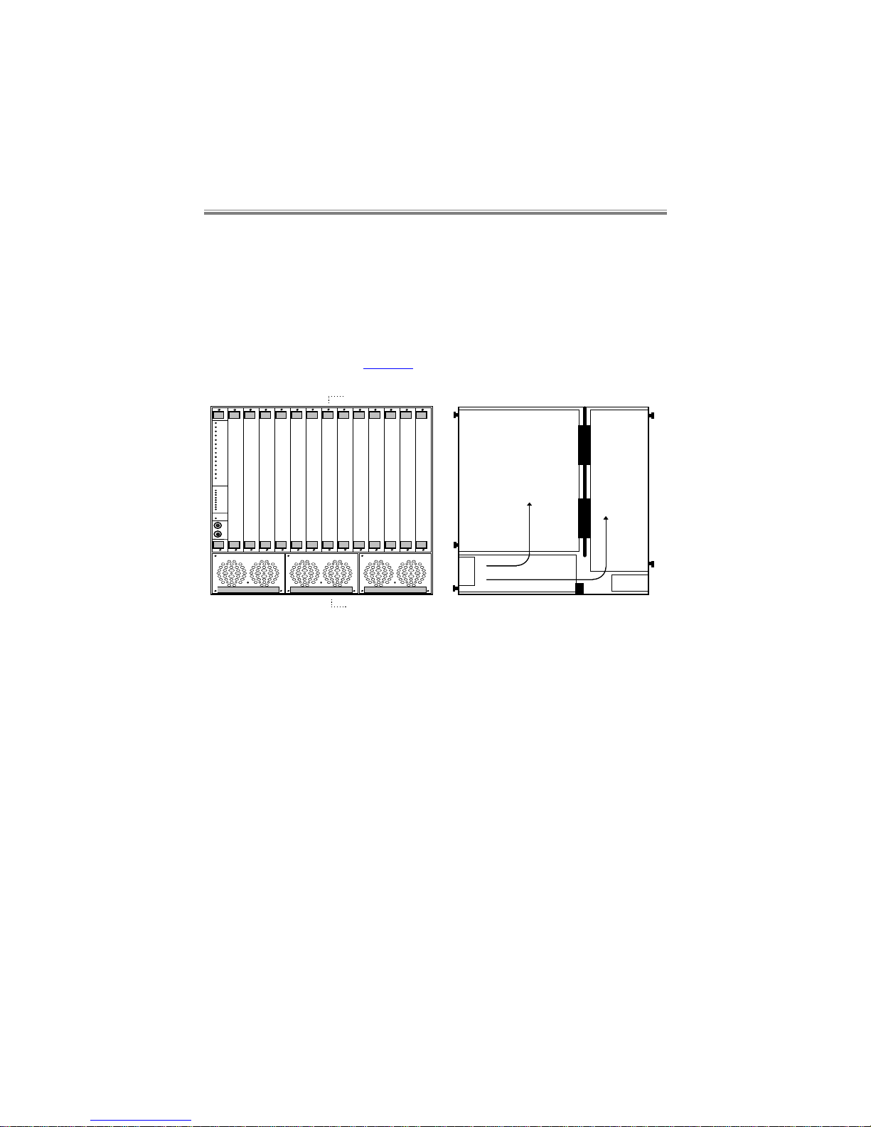
The SBU14C fits into a standard 19” cabinet system. There are
positions for 14 cards in all, including the SBUGSM or SBULSM.
Cooling is prov ided for t he shelf by fans i n the PSUs. I f onl y one or two
PSUs are fitted, then PSU blank panels must be fitted to the empty slots.
An illustration of the layout of the SBU14C and the flow of cooling air
through it, is shown in Figure 1:-
A
A
Fans
Air flow
Front
(Application)
Card
Rear
(Interface)
Card
IEC
Connector
Section through ‘AA’
PSU
F
IVEMERE
F
IVEMERE
F
IVEMERE
Figure 1 SBU14C
Each power inlet individually feeds each power supply module.
Page 9
Scope and Introduction
80-30200000-03 1-3
1.4 The SBU6C
The SBU6C is designed to be either a ‘Desk Top’ unit, a ‘Tower’ unit
under a desk, or a shelf mounted uni t In a standard 19” cabinet ( by the
addition of mounting ‘ears’).
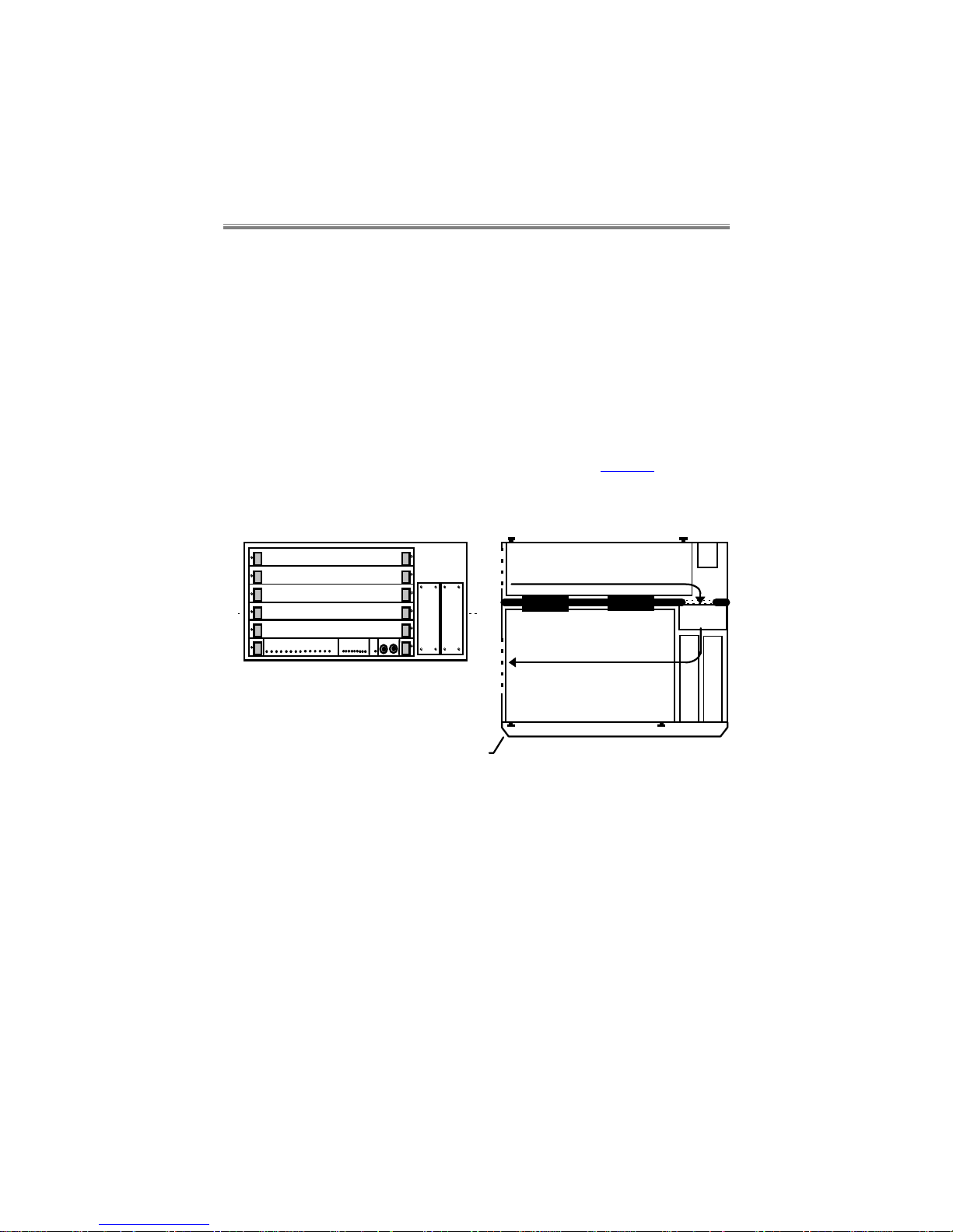
There are positions for 6 cards in all, including the SBUGSM or
SBULSM.
When operati ng i n ‘Desk Top’ or ‘T ower’ modes, pl asti c f eet are suppli ed
on the relevant face of the enclosure.
Cooling is provided by a permanently installed fan (
i.e.
not in the PSUs).
An illustration of the layout of the SBU6C is shown in Figure 2:-
A
A
Fan
Air
Front
(Application)
Cards
Rear
(Interface)
Cards
Section
through
‘AA’
PSUs
Acrylic
Cover
IEC
Mains
Inlet
Air
Figure 2 SBU6C
Each power inlet individually feeds each power supply module.
Page 10

Installation and Cabling
80-30200000-03 2-1
2. Installation and Cabling
The SBU14C is a high densi ty r ack m ount ed unit designed t o si t in a 19"
comm unications cabinet . It has eight f ixi ng points, f our down each side
of the front of the frame. Al l eight f i x i ng point s must be securel y fix ed to
the frame.
The SBU6C can be rack m ount ed by t he addi t ion of rack m ount i ng ear s.
The ears must be securely fixed to the frame.
2.1 Mains Input and Wiring
On the rear of t he unit there ar e three IEC m ains sockets (for SB U14C)
or two IEC mains sockets (for SBU6C) for connection to independent
mains supplies. The primary earth connection is made via these
sockets.
WARNING - these appliances must be earthed.
VORSICHT - Nur eine vorschriftsmäßig geerdete Steckdose
anschließen.
Mains cables, 2 metres in length are supplied with both units. These
should be connected to a suit able mai ns supply. The m ains plug is the
primar y disconnect dev ice for the uni t. Ensure that the uni t is i nstalled
near to socket outlets and that the outlets are easily accessible.
The mai ns cables supplied with the uni t are fi tted with m oulded 13 am p
plugs for connection to standard socket outl ets. Should t he plugs not be
of the correct t ype for the outlet s that they are connected to, t he plugs
Page 11

SBU Systems
User Manual
80-30200000-032-2
should be remov ed and the cable re-wired to the correct type of plug.
The use of adaptors is not recommended.
The wires in the supply cord are coloured in accordance with the
following code:-
Green and Yellow Earth
Blue Neutral
Brown Live
As these colours may not correspond with the termi nations in the plug
being used, it should be connected as follows:-
The green and yellow wire must be connected to the terminal marked
with the let ter E , or wit h the ear th sym bol , or c olour ed green, or col oured
green and yellow.
The blue wire must be connected t o the termi nal marked with t he letter
N, or coloured black, or coloured blue.
The brown wire must be connect ed to t he term i nal m arked wit h the l ett er
L, or coloured red, or coloured brown.
All dat a com m uni cati ons li nks to t he f ram e shoul d be i n ac cordance wit h
the cable specif ications giv en in the appropriate manual for each card
type. The rear panel connectors have been fitted with 4-40 screw-locks.
WARNING:
Only connect apparatus complying with the requirements of
SELV in accordance with clause 2.3 of EN 60 950 to the
connector ports on the backplane.
Geräte nur in Übereinstimmung mit den Anforderungen der
SELV entsprechend Absatz 2.3 der EN 60 950 an den
Anschlußbuschen der rückwärtigen Platte anschliessen.
Page 12

Installation and Cabling
80-30200000-03 2-3
2.2 Supply Ratings and Fusing
WARNING:
1. Caution - for continued protection against risk of fire,
replace only with same type and rating of fuse.
Achtung - für fortwärenden Schutz vor Feuergefahr nur
Sicherungen derselben Art und derselben Auslegung
einsetzen.
2. The Shelf should be professionally installed by a competent
engineer. There are no operator serviceable parts inside
the unit and it should only be opened by a qualified service
engineer. The mains supply should be disconnected before
accessing the interior.
Gefäh! Bereich. Nur für fachpersonal. Nicht öffnen
berührungsgefahr!
3. Where the Shelf is not completely complemented with
application cards, blank panels must be fitted to all vacant
slots both front and rear for user safety and EMC
compliance reasons.
2.2.1 SBU14C
The unit can be connected to supplies of the following voltage ranges:a) 90VAC to 132VAC (110 to 120V Nominal)
b) 180VAC to 264VAC (220 to 240V Nominal)
Supply frequencies, in all cases, can be in the range 48Hz to 62Hz.
The maximum power consumption of each power supply unit is 200
watts. The current requirement for each of the voltage ranges is:a) 1A max.
b) 0.5A max.
Ideal mains inlet fuse rating:
20mm x 5mm, 2AH, 250V Anti-surge (T) type for 110V to 120V and
220V to 240V ratings.
Page 13

SBU Systems
User Manual
80-30200000-032-4
Ideal power supply fuse rating:
20mm x 5mm, 3.15AH, 250V Anti-surge (T) ty pe for 110V to 120V and
220V to 240V ratings.
2.2.2 SBU6C
The unit can be connected to supplies of the following voltage range:93VAC-264VAC (110 to 120V, and 220 to 240V Nominal voltages)
Supply frequencies, in all cases, can be in the range 47Hz to 63Hz.
The maxi m um power consumption of eac h power supply unit i s 80 watts.
The current requirement for each of the voltage ranges is:-
0.8A for 110 to 120V range
0.4A for 220 to 240V range.
Ideal mains inlet fuse rating:
20mm x 5mm, 2.5AH, 250V Anti-surge (T) type for 110V to 120V and
220V to 240V ratings.
Ideal power supply fuse rating:
20mm x 5mm, 2.5AH, 250V Anti-surge (T) type for 110V to 120V and
220V to 240V ratings.
Page 14
Installation and Cabling
80-30200000-03 2-5
2.3 Power Supply Capacities/Redundancy
2.3.1 SBU14C
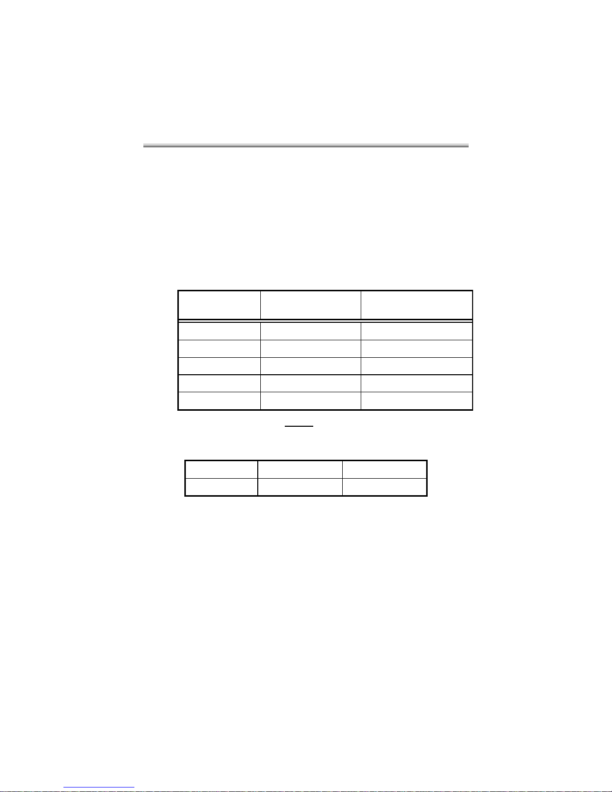
Up to 3 power supplies can be fit ted to the 19” Shelf system. E ach one
is capable of providing the complete Shelf power r equirement (at 120W).
It’s a matt er of choice whether one, t wo or three PSUs are f itted, such
decision generally being based upon the redundancy/reliability versus
the load requirement of the equipment fitted.
The SBU14C can therefore operate in the following modes with one, two
or three PSUs :-
No of PSUs Power
Requirement
Redundancy status
One PSU 120W no redundancy
Two PSUs 120W full redundancy
Two PSUs 240W no redundancy
Three PSUs 240W full Redundancy
Three PSUs 360W no redundancy
The above ratings reflect the overall output capacity of the supply.
Each of the SBU14C power supply modules can deliver the following
maximum currents:
+5V +12V -12V
10A 6.5A 1A
When i nstalling cards into the SBU14C, the installation engineer must
ensure that the shelf power supplies’ combined outputs can meet both
the overall power requirements and the individual rail current
requirem ents of all t he cards in the shelf. (Please refer to the relev ant
manuals for thi s inform ati on on the cards). This is tr ue whether allowing
for redundancy or not.
Page 15
SBU Systems
User Manual
80-30200000-032-6
2.3.2 SBU6C
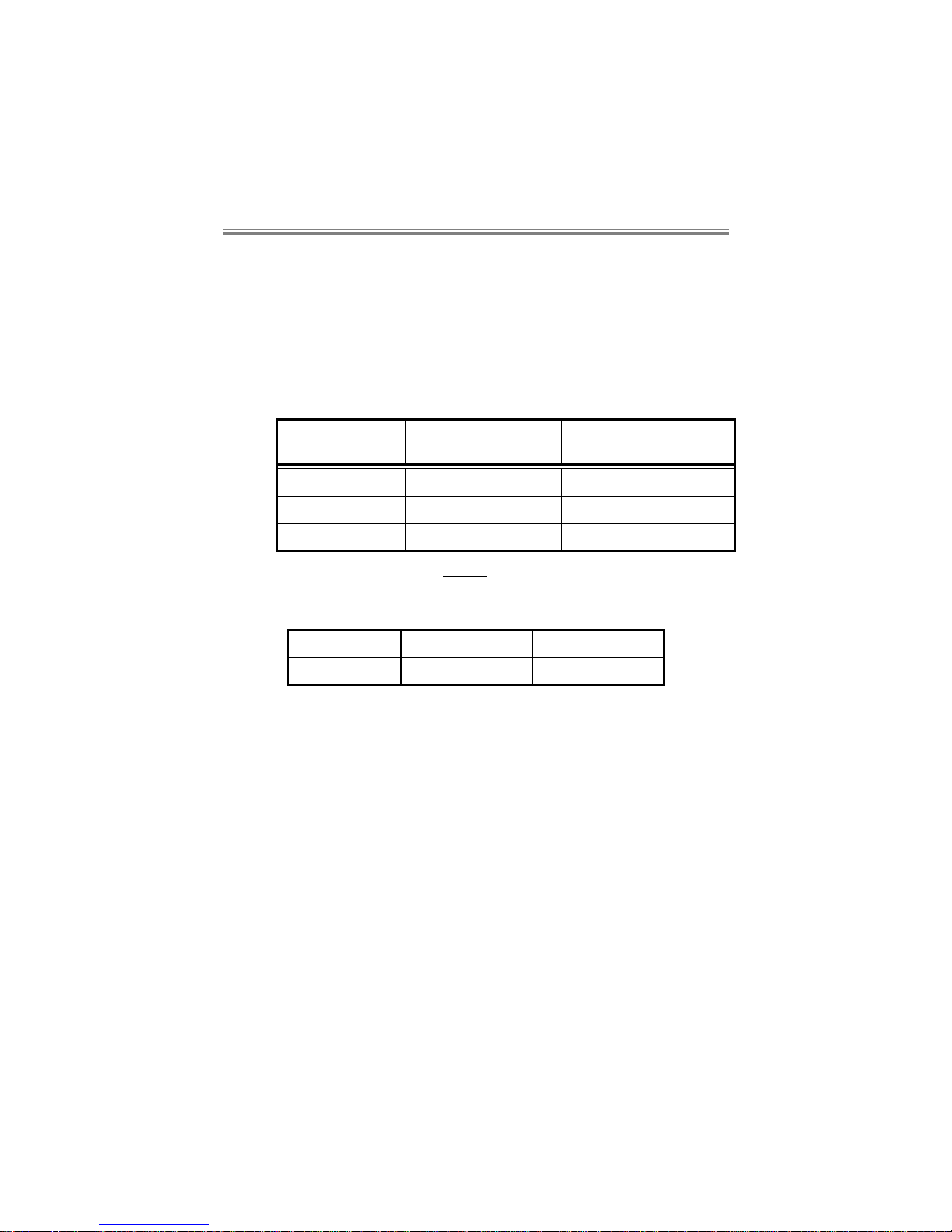
Up to 2 power supplies can be fit ted t o the S BU6C. E ach one i s capable
of providing the complete Shelf power requirement (at 50W). It’s a
matter of choice whether one or two PSUs are fitted, such decision
generally being based upon the redundancy/reliability versus the load
requirement of the equipment fitted.
The SBU6C can therefore operate in the following modes with one or two
PSUs :-
No of PSUs Power
Requirement
Redundancy status
One PSU 50W no redundancy
Two PSUs 50W full redundancy
Two PSUs 100W no redundancy
The above ratings reflect the overall output capacity of the supply.
Each of the SBU6C power supply modules can deliver the following
maximum currents:
+5V +12V -12V
5A 1A 1A
When installing cards into the SBU6C, the installation engineer must
ensure that the shelf power supplies’ combined outputs can meet the
indiv idual rail current requirem ents of all the cards in the shelf . (Pl ease
refer to the relev ant manuals for thi s informat ion on the cards). Thi s is
true whether allowing for redundancy or not.
Page 16

Overview of Shelf Modules
80-30200000-03 3-1
3. Overview of Shelf Modules
This section is intended to provide a brief overview of standard
equipment fitted in the SBU6C and SBU14C Shelf Systems.
3.1 Power Supplies
3.1.1 SBU14C
Up to 3 power supplies can be fi tted t o the SBU14C. Each one capable
of providing the complete Shelf power requirement (at 120W) It’s a
matter of choice whether one, two or three PSUs are f itted, such decision
generally being based upon the redundancy/reliability versus the load
requirement of the equipment fitted.
Please see section 2.3 for more information on this.
3.1.2 SBU6C
Up to 2 power supplies can be fit ted t o the S BU6C. E ach one i s capable
of providing the complete Shelf power requirement (at 50W). It’s a
matter of choice whether one or two PSUs are fitted, such decision
generally being based upon the redundancy/reliability versus the load
requirement of the equipment fitted.
Please see section 2.3 for more information on this.
Page 17

SBU Systems
User Manual
80-30200000-033-2
3.2 Cooling
3.2.1 SBU14C
Cooling f or the whole SBU14C system is provi ded by the fans m ounted
in the PSUs. The fans are driven directly from the shelf backplane
,
running whether or not t he PSU(s) are operational . If any fan f ails t hen
the fan f ai l ure signal i s moni t ored by t he SBUG SM/ SBULSM , and out put
as an ALERT.
Any unused power supply positions must be covered by a blanking plate.
3.2.2 SBU6C
Cooling i s prov i ded by a perm anent l y i nstall ed f an (
i.e.
not in the PS Us).
The status of this fan is available to the SBUGSM/SBULSM, and an
ALERT is generated should the fan fail.
3.3 Generic Shelf Manager Module (SBUGSM)
The SBUGSM pr ovides managem ent for all applicati on cards mounted
in either Shelf providing the focus for network (and terminal)
management activities.
Please see section 4 for a detailed description of this module.
3.4 LAN Shelf Manager Module (SBULSM)
The SBULSM front card provides the same facilities as the SBUGSM
and in additi on has a Local Area Network “10baseT” (LAN) port. This
port provides the following additional features:-
• Telnet acc ess for managem ent of al l cards in the shelf v ia t he LAN
connection
• SNMP Trap reporting of ALERTs from all cards.
There is a choice of SBULSM rear panels. The SBULSM rear panel
provides the LAN connectivity. With the SBUGSM rear panel, no
additional facilities are provided over the SBUGSM.
3.5 Generic Port Sharer Module (SBUGPS)
The SBUGPS is a 7-channel uni t. It resides in ei ther Shelf in or der to
allow a user to control up to 7 managem ent channels f rom one term inal .
Page 18

Overview of Shelf Modules
80-30200000-03 3-3
These management channels can be eit her SBUG SM/ SBULS M m odul es
or other Fivemere managed equipment.
Please see section 6 for a detailed description of this module.
Page 19

Generic Shelf Manager Module
80-30200000-03 4-1
4. Generic Shelf Manager Module
4.1 Overview
The Generic Shelf Manager Card (the SBUGSM) provi des management
for all application cards mounted in either the SBU14C or SBU6C
providing the focus for network (and terminal) management activities.
Please see section 5 for the LAN Shelf Manager Card.
The SBUGSM prov ides an interface between a terminal or port sharer
and a complete shelf of cards. It has an Alarm port and a Command
port which appear to a SBUGP S as a single card but off eri ng a range of
polling addresses.
The SBUGSM’s purpose is to m onit or t he status of the appl i cat ion c ards,
collect alarm messages from them and route them to the comm and or
alarm por t as appropriate, and also to c onfigure and control appl ication
cards in polled mode.
The SBUGSM communicates with the application cards (TA 64, Primary
Rate Module etc.) via the Configuration bus and System bus on the
backplane. No external connection is necessary.
Page 20
SBU Systems
User Manual
80-30200000-034-2
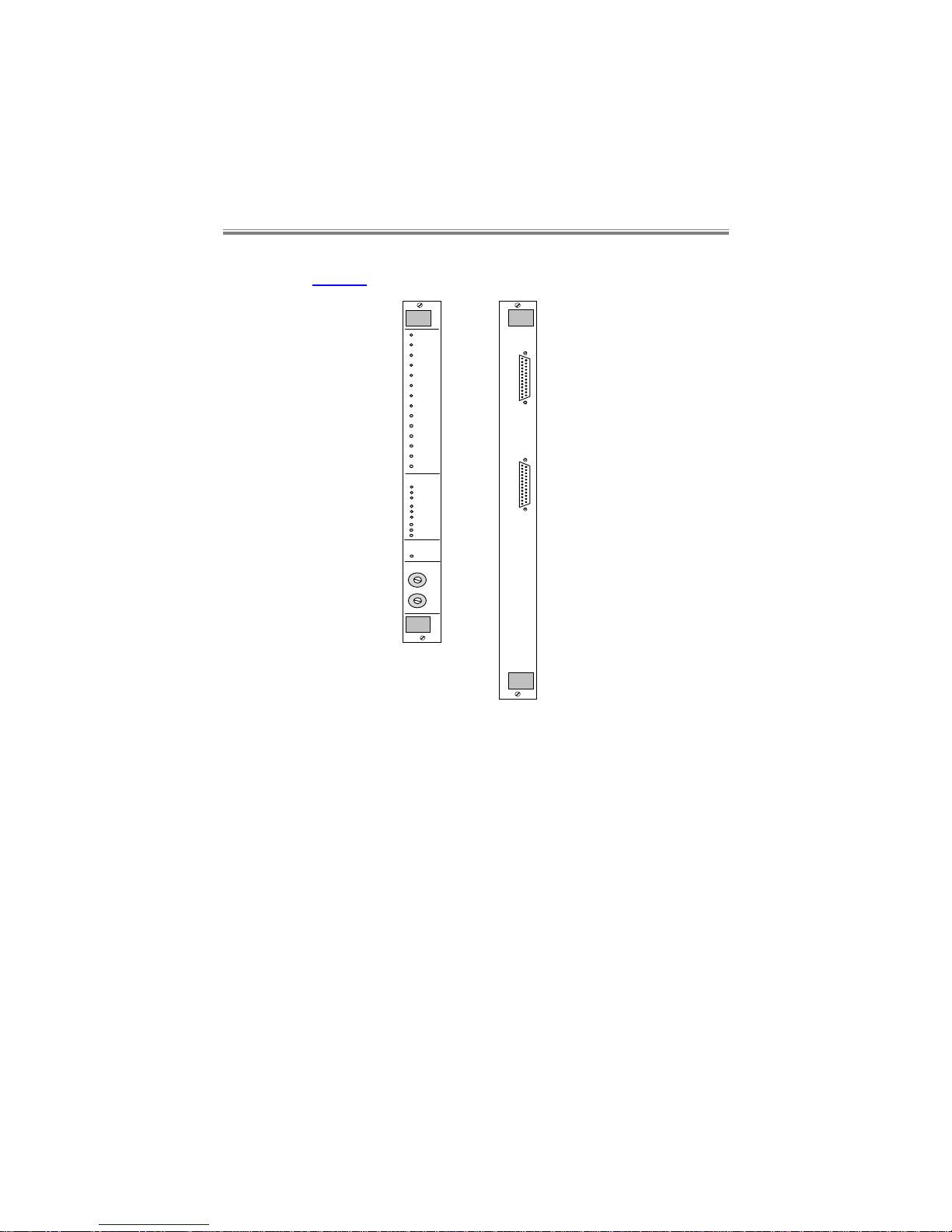
The front and rear panels of the cards which m ake up the SBUGSM are
shown in Figure 3:-
Rear
Command
Alarm
Front
AC 1
DC 1
Fan 1
AC 2
DC 2
Fan 2
AC 3
DC 3
Fan 3
PSU Status
Alert
Slot 1
Slot 2
Slot 3
Slot 4
Slot 5
Slot 6
Slot 7
Slot 8
Slot 9
Slot 10
Slot 11
Slot 12
Slot 13
Slot 14
Shelf Address
High
Low
GSM
CBU
Figure 3 Front and Rear Panels
4.2 Shelf Power Loading
The SBUGSM is fit ted into F iv emere SBU6C and SBU14C shel ves with
up to five (SBU6C) or thirteen (SBU14C) other application cards.
The SBUGSM requires the following current on the power rails:
+5V +12V -12V
150mA 25mA 25mA
Page 21

Generic Shelf Manager Module
80-30200000-03 4-3
When installing cards into the SBU6C and SBU14C, the installation
engineer must ensure t hat the shelf power supplies’ combined output can
meet the both the overall power requirements and the individual rail
current requirem ents of all the cards in the shelf. (Please refer to the
relev ant manual s for this inf ormat ion on the cards). T his is true whether
allowing for redundancy or not.
Warning:
The rack should be professionally installed by a competent
engineer. There are no operator serviceable parts inside the
unit and it should only be opened by a qualified service
engineer. The mains supply should be disconnected before
accessing the interior.
Gefäh! Bereich. Nur für fachpersonal. Nicht öffnen
berührungsgefahr!
4.3 Command access to the SBUGSM
Upon Shelf power up or SBUGSM card insertion into the Shelf, cards
have to be polled to gain access to them. Either the SBUGSM or
individual application cards can be polled, which is done via the
SBUGSM command Port in both cases.
4.3.1 Poll Addresses and Alert format
The poll address in the shelf is determined by the slot position of the
applicat ion card and also by the Shelf addr ess. This address is set via
the thumbwheel switches on the front panel.
In the following example the first 3 digits of the poll address (1-3)
comprise the Shelf address, the last two digits (4-5) the slot address.
12345-1 >
The Shelf address is hexadecimall y encoded, producing a decim al poll
address on the term inal com mand li ne. For ex ample i f the thum bwheel
switch was set to 2 (upper wheel) 3 (lower wheel) - 23
H
, the Shelf part of
the poll number will be decimal
032xx + 003xx = 035xx
where xx i s the actual card slot num ber. If the appl ication c ard was in
slot 13 (SBU14C), the full poll address would therefore be 03513.
Page 22

SBU Systems
User Manual
80-30200000-034-4
The SBUGSM can in fact be fitted into any slot in the Shelf but for
conveni ence it is usually put i nto slot 1, the lef t hand slot looking f rom
the front. In this slot the address is 01.
The SBUGSM can be addressed in any slot by typing
poll_<Shelf address>
where <Shelf address> is the slot number where the SBUGSM resides.
poll_3
will address the SBUGSM in slot 3. The SBUGSM in the addressed
Shelf will respond with its actual poll number in both cases.
poll_0
will address the SBUGSM in any slot.
The command prom pt comprises two spaces followed by a '>' and t hen
another space e.g.
__>_
The space preceding the '>' may also be used as a channel identifier e.g.
_1>_ To indicate you are using channel 1 on an application card
On the SBUGSM management card a 'M' is used e.g.
_M>_ To indicate you are using a management card.
The format for normal and alert messages comprise the following:
A five digit poll number and a dash,
Time & date stamp with space, dash, space (‘long format’ ALERTs only),
Space, channel number, colon, space, Message e.g.
Alert message going to the command port or alarm port:
00008-_1:_ALERT_Incoming_call_()
where ‘short format’ messages are selected, or
00008-04/07/94_11:00:04_-__1:_ALERT_Incoming_call_()
where ‘long format’ messages are selected, showing the time and
date stamp.
Page 23

Generic Shelf Manager Module
80-30200000-03 4-5
4.3.2 Factory Default
The highest thum bwheel address FFH is reserved f or fact ory defaulti ng
the SBUGSM. Therefore the highest available Shelf address is FE
which corresponds to a maximum of 255 Shelves.
4.3.3 Password Entry
When t he menu system is started up f or the fi rst time (at login) and a
card is polled, then the command menu will prompt for a password
before granting you access to the menus. The factory def ault for this
password is upper case QWERTY<CR> but obviously this can then be
changed to a new password (min l ength 6 chars, max l ength 20 chars)
via the appropriate menu screen.
4.4 Interfaces
Both the Command Port and Al arm Port are V24/V28 interf aces using
fem ale ‘D’ type connectors on the rear panel. They ar e both confi gured
as DCE interfaces, accepting a 1:1 cable from a terminal or a subchannel of either the SBUGPS or the PSV4/1.
Both ports operate at 8 data bits, 1 start and 1 or 2 stop bits. Port data
rate can be set by software command, to alter the speed from the factor y
default of 9k6 bit/s.
Pin assignments on the 25-way connectors are:
Pin no. Circuit no Circuit name Source
1 GND Signal ground/chassis earth
2 103 Transmit Data DTE
3 104 Receive Data DCE
4 105 Request To Send DTE
5 106 Clear To Send DCE
6 107 Data Set Ready DCE
7 102 Signal Ground
8 109 Data Carrier Detect DCE
9 -19 Not used
20 108/2 Data Terminal Ready DTE
21-25 Not used
The alarm port additi onally has a power fail rel ay output. W ith power
applied to the SBUGSM, pin 14 i s connected via the relay contacts to
Page 24

SBU Systems
User Manual
80-30200000-034-6
pin 16. When power to the SBUG SM fail s, pin 14 is connected v ia the
relay contacts to pin 18.
4.5 Operation Menu (A)
The command structure for the command port is a menu driven system
with a hierarchical type of structure.
A) DISPLAY
ALERT LOG
Displays the last 100 ALERTs from all cards.
4.6 Configuration Menu (B)
The (F) i n the text denotes the fact ory defaul t setting. This i s achiev ed
by factory defaulting the unit (see section 4.3.2)
4.6.1 System Menu
A) SYSTEM
MENU
A) CHANGE
PASSWORD
Allows the user to change the
SBUGSM password.
*) POLL
NUMBER
This command is only available
for standalone units.
C) SET TIME
Enable the user to set the
SBUGSM real time clock.
D) SET DATE
Enables the user to set the date
of the real time clock.
Page 25

Generic Shelf Manager Module
80-30200000-03 4-7
4.6.2 Command Port Menu
A) SPEED A) 1200
Configures the speed of the
command port.
B) 2400
C) 4800
D) 9600 (F)
E) 19k2
F) 38k4
B) ECHO A) ENABLED (F)
B) DISABLED
C) CONSOLE A) NORMAL (F)
Used when connected
directed to the management
console.
B) POLLED
Used when the SBUGSM
Command Port is connected
to a SBUGPS or PSV/4.
D) FLOW
CONTROL
A) RTS/CTS
RTS/CTS flow control is
effective.
B) XON/XOFF
DC1/DC3 inband flow control
is effective.
C) DISABLED (F)
No flow control is used on the
Command Port.
E) ALERTS A) SHORT
FORMAT (F)
No time and date provided
with ALERTs.
B) LONG
FORMAT
Time and date stamp
provided with all ALERTs.
C) DISABLED
No ALERTs presented.
F) EVENTS A) ENABLED (F)
Events are presented
B) DISABLED
Events are not presented
Page 26

SBU Systems
User Manual
80-30200000-034-8
4.6.3 Alarm Port Menu
A) SPEED A) 1200
Configures the speed of the
Alarm port.
B) 2400
C) 4800
D) 9600 (F)
E) 19k2
F) 38k4
*) ECHO
No selection is possible.
C) CONSOLE A) NORMAL (F)
Used when the SBUGSM
Alarm Port is connected
directly to the management
console.
B) POLLED
Used when the SBUGSM
Alarm Port is connected to a
SBUGPS or PSV4/1.
D) FLOW
CONTROL
A) RTS/CTS (F)
RTS/CTS flow control is
effective.
B) XON/XOFF
DC1/DC3 inband flow control
is effective.
C) DISABLED
No flow control is used on the
Command Port.
E) ALERTS A) SHORT
FORMAT
No time and date provided
with ALERTs.
B) LONG
FORMAT
Time and date stamp
provided with all ALERTs.
C) DISABLED (F)
No ALERTs presented.
F) EVENTS A) ENABLED
Events are presented.
B) DISABLED (F)
Events are not presented.
Page 27

Generic Shelf Manager Module
80-30200000-03 4-9
4.6.4 Alarms menu
A) PASSWORD
A) ENABLED (F)
Sends an alert indicating when
whenever three successive incorrect
attempts have been made to log in
to the menu system:-
ALERT Unauthorised access
attempt
B) DISABLED
This ALERT is disabled.
4.7 Logout (C)
This comm and logs the user out of access to the card that is actively
polled. If the SBUGSM is acti vely pol l ed then i n addi ti on t he user is also
logged out of password access.
Page 28

LAN Shelf Manager Module
80-30200000-03 5-1
5. LAN Shelf Manager Module
5.1 Overview
The LAN Shelf Manager Card (the SBULSM) in the same way as the
SBUGSM provides management for all application cards mounted in
either the SBU14C or SBU6C providing the focus for network (and
terminal) management activities. The SBULSM also provides access
from the LAN for management of the shelf via Telnet , and can output
ALERTs in SNMP trap format.
Please see section 4 for the Generic Shelf Manager Card.
The SBULSM provides an interf ace between a terminal or port sharer
and a complete shelf of cards. It has an Alarm port and a Command
port which appear to a SBUGP S as a single card but off eri ng a range of
polling addresses.
The purpose of the SBULSM is to moni tor the status of the appl ication
cards, collect alarm messages from them and route them to the
comm and, alarm or LAN port as appropri ate, and also to conf igure and
control application cards via the command port in polled mode or via
Telnet.
The SBULSM communicates with the applicati on cards (TA 64, Primar y
Rate Module etc.) via the Configuration bus and System bus on the
backplane. No external connection is necessary.
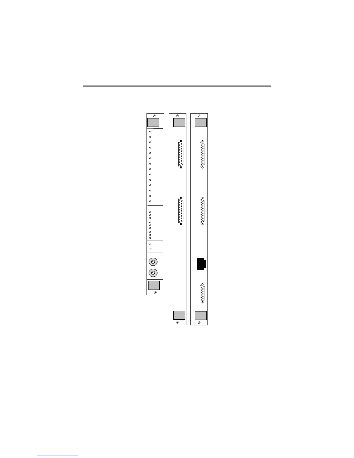
The front and rear panels of the car ds which make up the SBULSM are
shown in Figure 3. There is a choice of rear car d, the “sim ple” rear card
Page 29
SBU Systems
User Manual
80-30200000-035-2
being the same as the SBUGSM rear card, and not providing LAN
interconnection. The AUI interface is not supported at present.
LAN RearFront
Command
Alarm
Command
Alarm
Simple Rear
PSU Status
Slot 1
Slot 2
Slot 3
Slot 4
Slot 5
Slot 6
Slot 7
Slot 8
Slot 9
Slot 10
Slot 11
Slot 12
Slot 13
Slot 14
AC 1
DC 1
Fan 1
AC 2
DC 2
Fan 2
AC 3
DC 3
Fan 3
SBU
Talkw i re
Alert
Shelf Address
High
Low
AUI
10BaseT
LSM
Figure 4 SBULSM Front and Rear Panels
Page 30

LAN Shelf Manager Module
80-30200000-03 5-3
5.2 Shelf Power Loading
The SBULSM is fitt ed into Fiv emere SBU6C and S BU14C shelves with
up to thirteen other application cards.
The SBULSM requires the following current on the power rails:
+5V +12V -12V
250mA 25mA 25mA
When installing cards into the SBU6C or SBU14C, the installation
engineer must ensure t hat the shelf power supplies’ combined output can
meet the both the overall power requirements and the individual rail
current requirem ents of all the cards in the shelf. (Please refer to the
relev ant manual s for this inf ormat ion on the cards). T his is true whether
allowing for redundancy or not.
Warning:
The rack should be professionally installed by a competent
engineer. There are no operator serviceable parts inside the
unit and it should only be opened by a qualified service
engineer. The mains supply should be disconnected before
accessing the interior.
Gefäh! Bereich. Nur für fachpersonal. Nicht öffnen
berührungsgefahr!
5.3 Command access to the SBULSM
Upon Shelf power up or SBULSM card insertion into the Shelf, cards
have to be polled to gain access to them. Either the SBULSM or
individual application cards can be polled, which is done via the
SBULSM command Port in both cases.
5.3.1 Poll Addresses and Alert format
The poll address in the shelf is determined by the slot position of the
applicat ion card and also by the Shelf addr ess. This address is set via
the thumbwheel switches on the front panel.
In the following example the first 3 digits of the poll address (1-3)
comprise the Shelf address, the last two digits (4-5) the slot address.
Page 31

SBU Systems
User Manual
80-30200000-035-4
12345-1 >
The Shelf address is hexadecimall y encoded, producing a decim al poll
address on the term inal com mand li ne. For ex ample i f the thum bwheel
switch was set to 2 (upper wheel) 3 (lower wheel) - 23
H
, the Shelf part of
the poll number will be decimal
032xx + 003xx = 035xx
where xx i s the actual card slot num ber. If the appl ication c ard was in
slot 13, the full poll address would therefore be 03513.
The SBULSM can in fact be fitted into any slot in the Shelf but for
conveni ence it is usually put i nto slot 1, the lef t hand slot looking f rom
the front. In this slot the address is 01.
The SBULSM can be addressed in any slot by typing
poll_<Shelf address>
where <Shelf address> is the slot number where the SBULSM resides.
poll_3
will address the SBULSM in slot 3. The SBULSM i n the addr essed Shelf
will respond with its actual poll number in both cases.
poll_0
will address the SBULSM in any slot.
The command prom pt comprises two spaces followed by a '>' and t hen
another space e.g.
__>_
The space preceding the '>' may also be used as a channel identifier e.g.
_1>_ To indicate you are using channel 1 on an application card
On the SBULSM management card a 'M' is used e.g.
_M>_ To indicate you are using a management card.
The format for normal and alert messages comprise the following:
A five digit poll number and a dash,
Time & date stamp with space, dash, space (‘long format’ ALERTs only),
Page 32

LAN Shelf Manager Module
80-30200000-03 5-5
Space, channel number, colon, space, Message e.g.
Alert message going to the command port or alarm port:
00008-_1:_ALERT_Incoming_call_()
where ‘short format’ messages are selected, or
00008-04/07/94_11:00:04_-__1:_ALERT_Incoming_call_()
where ‘long format’ messages are selected, showing the time and
date stamp.
5.3.2 IP Address
The LAN interface requires an IP address so that the LSMM can be
identif ied (addressed) on the net work. The IP address is constructed of
four ‘quadrants’ in the form:-
131.202.87.112
The address is entered by the user, usually from a locally connected
management terminal or via a Talkwire call.
5.3.3 Factory Default
The highest thum bwheel address FFH is reserved f or fact ory defaulti ng
the SBULSM. Therefore the hi ghest avail able S helf address is FE which
corresponds to a maximum of 255 Shelves.
5.3.4 Password Entry
When t he menu system is started up f or the fi rst time (at login) and a
card is polled, then the command menu will prompt for a password
before granting you access to the menus. The factory def ault for this
password is upper case QWERTY<CR> but obviously this can then be
changed to a new password (min l ength 6 chars, max l ength 20 chars)
via the appropriate menu screen.
5.4 Interfaces
Both the Command Port and Al arm Port are V24/V28 interf aces using
fem ale ‘D’ type connectors on the rear panel. They ar e both confi gured
as DCE interfaces, accepting a 1:1 cable from a terminal or a subchannel of either the SBUGPS or the PSV4/1.
Page 33

SBU Systems
User Manual
80-30200000-035-6
Both ports operate at 8 data bits, 1 start and 1 or 2 stop bits. Port data
rate can be set by software command, to alter the speed from the factor y
default of 9k6 bit/s.
Pin assignments on the 25-way connectors are:
Pin no. Circuit no Circuit name Source
1 GND Signal ground/chassis earth
2 103 Transmit Data DTE
3 104 Receive Data DCE
4 105 Request To Send DTE
5 106 Clear To Send DCE
6 107 Data Set Ready DCE
7 102 Signal Ground
8 109 Data Carrier Detect DCE
9 -19 Not used
20 108/2 Data Terminal Ready DTE
21-25 Not used
The alarm port additi onally has a power fail rel ay output. W ith power
applied to the SBULSM, pin 14 is connected via the relay contacts to
pin 16. When power to the SBULSM fail s, pin 14 is connect ed via the
relay contacts to pin 18.
5.5 Operation Menu (A)
The command structure for the command port is a menu driven system
with a hierarchical type of structure.
A) DISPLAY
ALERT LOG
Displays the last 100 ALERTs from all cards.
5.6 Configuration Menu (B)
The (F) i n the text denotes the fact ory defaul t setting. This i s achiev ed
by factory defaulting the unit (see section 4.3.2)
Page 34

LAN Shelf Manager Module
80-30200000-03 5-7
5.6.1 System Menu
A) SYSTEM
MENU
A) CHANGE
PASSWORD
Allows the user to change the
SBULSM password.
*) POLL
NUMBER
This command is only available
for standalone units.
C) SET TIME
Enable the user to set the
SBULSM real time clock.
D) SET DATE
Enables the user to set the date
of the real time clock.
5.6.2 Command Port Menu
A) SPEED A) 1200
Configures the speed of the
command port.
B) 2400
C) 4800
D) 9600 (F)
E) 19k2
F) 38k4
B) ECHO A) ENABLED (F)
B) DISABLED
C) CONSOLE A) NORMAL (F)
Used when connected
directed to the management
console.
B) POLLED
Used when the SBULSM
Command Port is connected
to a SBUGPS or PSV4/1.
Page 35

SBU Systems
User Manual
80-30200000-035-8
D) FLOW
CONTROL
A) RTS/CTS
RTS/CTS flow control is
effective.
B) XON/XOFF
DC1/DC3 inband flow control
is effective.
C) DISABLED (F)
No flow control is used on the
Command Port.
E) ALERTS A) SHORT
FORMAT (F)
No time and date provided
with ALERTs.
B) LONG
FORMAT
Time and date stamp
provided with all ALERTs.
C) DISABLED
No ALERTs presented.
F) EVENTS A) ENABLED (F)
Events are presented
B) DISABLED
Events are not presented
Page 36

LAN Shelf Manager Module
80-30200000-03 5-9
5.6.3 Alarm Port Menu
A) SPEED A) 1200
Configures the speed of the
Alarm port.
B) 2400
C) 4800
D) 9600 (F)
E) 19k2
F) 38k4
*) ECHO
No selection is possible.
C) REPORTING A) LOCAL (F)
All ALERTs are reported
locally via the Alarm Port.
B)*
Remote (ISDN)
C) SNMP
All ALERTs are reported as
SNMP traps via the LAN.
D) FLOW
CONTROL
A) RTS/CTS (F)
RTS/CTS flow control is
effective.
B) XON/XOFF
DC1/DC3 inband flow control
is effective.
C) DISABLED
No flow control is used on the
Command Port.
E) ALERTS A) SHORT
FORMAT
No time and date provided
with ALERTs.
B) LONG
FORMAT
Time and date stamp
provided with all ALERTs.
C) DISABLED (F)
No ALERTs presented.
F) EVENTS A) ENABLED
Events are presented.
B) DISABLED (F)
Events are not presented.
Page 37

SBU Systems
User Manual
80-30200000-035-10
5.6.4 Alarms menu
A) ALERT PASSWORD
A) ENABLED (F)
Sends an alert indicating when
whenever three successive incorrect
attempts have been made to log in
to the menu system:-
ALERT Unauthorised access
attempt
B) DISABLED
This ALERT is disabled.
*) ALERT DIALLING
*) ALERT INCOMING CALL
*) ALERT CHANNEL STATUS
Page 38

LAN Shelf Manager Module
80-30200000-03 5-11
E) ALERT SYSTEM
Sends an alert indicating that a call
attempt failed due to an insufficient
number of ‘B’-Channels being
available. The alert message is:
ALERT Insufficient BChannels
A) ENABLED (F)
Sends an ALERT indicating system
states:
ALERT System 0 Bank A
When the unit has booted from
Bank A Flash.
ALERT System 0 Bank B
When the unit has booted from
Bank B Flash.
ALERT System 1
When the NVRAM has been
defaulted, due to the NVRAM being
corrupted, reset, or a request for it
to be restored.
B) DISABLED
This ALERT is disabled.
5.6.5 Remote Port menu
Starred out, as this is not currently available.
5.6.6 Number Store menu
Starred out, as this is not currently available.
5.6.7 LAN menu
These sub-menus are available only when the LAN rear card is used.
Page 39

SBU Systems
User Manual
80-30200000-035-12
A) IP ADDRESS
This is a unique 32-bit address that
identifies the unit on the network.
Enter the IP address in the following
format, using a dot as a separator:-
xxx.xxx.xxx.xxx
B) SUBNET MASK
This is used by the routing mechanism
to determine whether another IP
address is on the same subnet as this
unit. If not, information is sent via the
default gateway.
C) DEFAULT GATEWAY
This address specifies an IP address
on this unit's subnet, used for
forwarding information to other
subnets. The default gateway address
can be blank (enter a blank line for
this) if all network traffic is to and from
units on this unit's sub-net.
Enter the default gateway address in
the following format, using a dot as a
separator:-
xxx.xxx.xxx.xxx
D) TRAP DESTINATIONS
A) STORE ADDRESS
These stores contain the
remote IP address destinations
for outgoing SNMP Traps, that
are created from all card
ALERTs.
Enter the destination addresses
in the following format, using a
dot as a separator:-
xxx.xxx.xxx.xxx
Traps are sent to all
destinations simultaneously.
B) DELETE ADDRESS
Page 40

LAN Shelf Manager Module
80-30200000-03 5-13
C) LIST ADRESS
D) LIST ALL
ADDRESSES
E) TELNET IDLE TIMEOUT
This timeout disconnects a
telnet session if it has been left
idle for a given period of time.
ENTER TIME IN MINUTES
FOR TELNET IDLE
TIMEOUT: (0-60 minutes,
Default 10; 0 means no
timeout).
F) SNMP A) COMMUNITY
Enter a string value, the input
being terminated by a <cr>.
This may be between 0 and 59
characters inclusive, terminated
with a <cr>.
The factory-default value for
this setting is:-
Public
Entering a blank line clears the
entry.
B) AUTHENTICATION
TRAPS
When enabled, these traps are
produced when the LSMM
receives requests that have
community strings that do not
match the LSMM’s community
string.
A) ENABLED (F)
B) DISABLED
Page 41

SBU Systems
User Manual
80-30200000-035-14
C) SYSCONTACT
The name needs to be entered
of the contact person for this
managed node, together with
information on how to contact
this person.
This may be between 0 and 59
characters inclusive, terminated
with a <cr>.
Entering a blank line clears the
entry.
D) SYSNAME
This is the name for this
managed node. By convention,
this is the node's fully qualified
domain name.
This may be between 0 and 59
characters inclusive, terminated
with a <cr>.
Entering a blank line clears the
entry.
E) SYSLOCATION
This is the physical location of
this node (e.g.,`telephone
closet, 3rd floor').
This may be between 0 and 59
characters inclusive, terminated
with a <cr>.
Entering a blank line clears the
entry.
5.7 Logout (C)
This comm and logs the user out of access to the card that is actively
polled. I f t he SBULSM is act ively poll ed t hen in addi ti on the user i s al so
logged out of password access.
Page 42

Generic Port Sharer
80-30200000-03 6-1
6. Generic Port Sharer
This section describes the Fivemere 7 channel Generic Port Sharer
Module (SBUGPS) which resides in a SBU14C or SBU6C in order to
allow a user to control up to 7 managem ent channels f rom one term inal .
These management channels can be eit her SBUG SM/ SBULS M m odul es
in other shelves or other Fivemere managed equipment.
The SBUGPS is similar to the PSV4/1 in function.
6.1 Physical Requirements
The SBUGPS fits i n a S B U14C or S B U6C and has 7 channel inputs, plus
one Master Port.
A SBUGPS i s com posed of a front ‘appl ic ati on’ card and a rear i nterface
card and takes up one slot in a SBU14C or SBU6C.
6.2 Panel Layouts
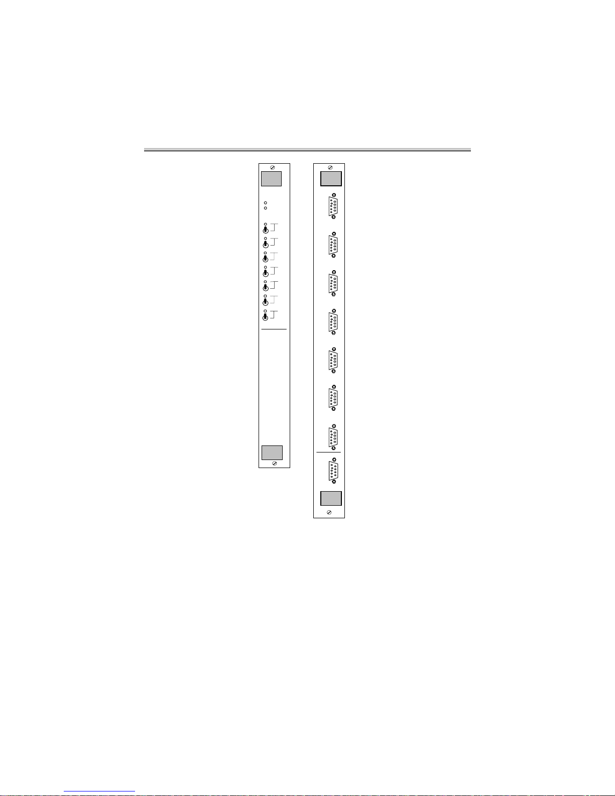
The front and rear panel layouts for the SBUGPS are shown in Figure 5.
Page 43
SBU Systems
User Manual
80-30200000-036-2
Rear
CH1
CH2
CH3
CH4
CH5
CH6
CH7
M
A
S
T
E
R
Front
RXD
TXD
1
OFF
2
OFF
3
OFF
4
OFF
5
OFF
6
OFF
7
OFF
SBU
GPS
Figure 5 SBUGPS Front and Rear Panels
Page 44

Generic Port Sharer
80-30200000-03 6-3
6.3 Shelf Power Loading
The SBUGPS is fitted into Fivemere Generic type shelves with a
SBUGSM/SBULSM and up to twelve other application cards.
The SBUGPS requires the following current on the power rails:
+5V +12V -12V
50mA 25mA 25mA
When installing cards into the SBU6C or SBU14C, the installation
engineer must ensure t hat the shelf power supplies’ combined output can
meet the both the overall power requirements and the individual rail
current requirem ents of all the cards in the shelf. (Please refer to the
relev ant manual s for this inf ormat ion on the cards). T his is true whether
allowing for redundancy or not.
Warning:
The rack should be professionally installed by a competent
engineer. There are no operator serviceable parts inside the
unit and it should only be opened by a qualified service
engineer. The mains supply should be disconnected before
accessing the interior.
Gefäh! Bereich. Nur für fachpersonal. Nicht öffnen
berührungsgefahr!
6.4 Functional Description
The SBUGPS al lows the connecti on of up to 7 channels at a t im e to the
Master Port. Lockout switches on the front of the panel allow one or
more of the channel s to be disabled i f necessary. T he SBUGPS has no
“intelligence” of its own, and polling is dealt with by t he devices which
are connected to it. The SBUGPS is shelf mounted, but it has no
communication with any other devices on that shelf.
6.5 Physical Interface
Seven 9-pin ‘D’-type female connectors are used for the selection
channels, and one 9-pin ‘D’-type female connector for the Master Port.
Page 45
SBU Systems
User Manual
80-30200000-036-4
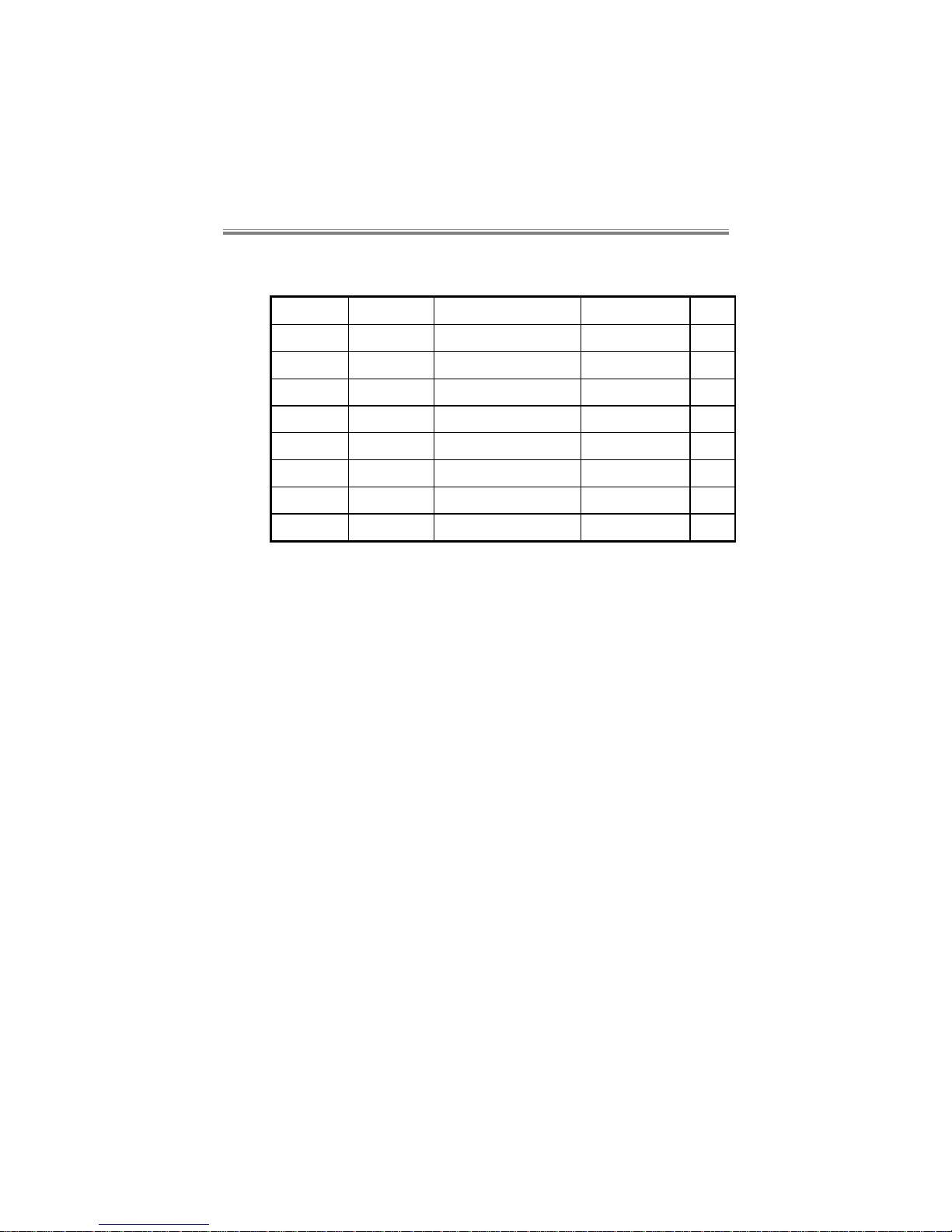
The pin connections for both the Master Port and channels are shown
below:-
Cct. No. Direction Signal Name Abbreviation Pin
109 from DCE Data Carrier Detect DCD 1
104 from DCE Receive data RxD 2
103 to DCE Transmitted data TxD 3
108/2 to DCE Data terminal ready DTR 4
- - Signal Ground SG 5
107 from DCE Data set ready DSR 6
105 to DCE Ready to send RTS 7
106 from DCE Ready for sending CTS 8
Switches on the f r ont of the car d allow locking out of individual channels,
should the need arise.
Green LED indicators show which channels are selected by poll ing or the
momentary transmission of ALERTs from another channel.
6.6 Card Jumpers
There are some links on the rear int erf ac e card which det erm i ne how the
interfaces are set up. There are no links on the front card.
None of the DCD jumpers are usually fitted as the DCD signal is not
used. The channel CTS jumpers must be positi oned over pins 2 and 3
on the channels for the polling selection to function.
If the Master Port is connected to another SBUG PS or PSV4/1 then the
CTS jumper must be similarly set. If connected to the management
console, the console may require this jumper over pins 1 and 2 to
provide CTS permanently to it.
Page 46

Generic Port Sharer
80-30200000-03 6-5
See below for these links:
JP3 Master Port
DCD
1-2 From Master port CTS (F)
2-3 From Master Port DSR
JP4 Master Port
CTS
1-2 Looped from Master Port RTS (F)
2-3 From internal CTS
JP5 Channel 1 DCD 1-2 From channel 1 CTS
2-3 From channel 1 DSR
JP6 Channel 2 DCD 1-2 From channel 2 CTS
2-3 From channel 2 DSR
JP7 Channel 3 DCD 1-2 From channel 3 CTS
2-3 From channel 3 DSR
JP8 Channel 4 DCD 1-2 From channel 4 CTS
2-3 From channel 4 DSR
JP9 Channel 5 DCD 1-2 From channel 5 CTS
2-3 From channel 5 DSR
JP10 Channel 6 DCD 1-2 From channel 6 CTS
2-3 From channel 6 DSR
JP11 Channel 7 DCD 1-2 From channel 7 CTS
2-3 From channel 7 DSR
JP12 Channel 1 CTS 1-2 Looped from Channel 1 RTS
2-3 From internal (selected) CTS (F)
JP13 Channel 2 CTS 1-2 Looped from Channel 2 RTS
2-3 From internal (selected) CTS (F)
JP14 Channel 4 CTS 1-2 Looped from Channel 4 RTS
2-3 From internal (selected) CTS (F)
JP15 Channel 5 CTS 1-2 Looped from Channel 5 RTS
2-3 From internal (selected) CTS (F)
JP16 Channel 6 CTS 1-2 Looped from Channel 6 RTS
2-3 From internal (selected) CTS (F)
JP17 Channel 3 CTS 1-2 Looped from Channel 3 RTS
2-3 From internal (selected) CTS (F)
JP18 Channel 7 CTS 1-2 Looped from Channel 7 RTS
2-3 From internal (selected) CTS (F)
Page 47

Shelf Specifications
80-30200000-03 7-1
7. Shelf Specifications
7.1 SBU14C
Dimensions
482mm W; 400mm H (9U);
360mm D
Mains Voltage
90-132V (110-120V nominal)
180-264V (220-240V nominal)
Consumption
200VA max. (per PSU)
Frequency
50/60Hz nominal
Mains Rear Panel
Fuses
2AH, 250V Anti-Surge (T)
20x5mm (110-120V and 220240V ranges)
Environment
Ambient temperature:
Operating 0°C to 40°C
Storage -20°C to 70°C
Relative Humidity: 10% to
90% non-condensing
Page 48

SBU Systems
User Manual
80-30200000-037-2
7.2 SBU6C
Dimensions
435mm W; 222mm H (5U);
357mm D, when as a Desk Top
unit.
Mains Voltage
93-264VAC (110-120V, 220240V nominals)
Consumption
80VA max. (per PSU)
Frequency
50/60Hz nominal
Mains Rear Panel
Fuses
2.5AH, 250V Anti-Surge (T)
20x5mm (110-120V and 220240V ranges)
Environment
Ambient temperature:
Operating 0°C to 40°C
Storage -20°C to 70°C
Relative Humidity: 10% to
90% non-condensing
Page 49

Cabling Diagrams
80-30200000-03 8-1
8. Cabling Diagrams
The foll owing cable specifi cations are those recommended f or use with
the SBUGSM/SBULSM and SBUGPS.
Wher e the SB UGSM /SB ULSM i s ment i oned, t his equall y appl ies to a 25
way ‘D’ connector of a Comm and or Alarm port of a standal one product
providing that it is capable of Polled Management, as the interface
operation is the same.
8.1 PC 9 Way to SBUGSM/SBULSM
This is used for connection of a PC 9 way male connector to the
SBUGSM/SBULSM Command or Alarm port.
Male
25 Way
‘D’
Female
9 Way
‘D’
3
2
7
8
5
6
4
2
3
4
5
7
6
20
Cable SPEC0123 is available for this application.
Page 50

SBU Systems
User Manual
80-30200000-038-2
8.2 PC 25 Way to SBUGSM/SBULSM
This is used for connection of a PC 25 way male connector to the
SBUGSM/SBULSM Command or Alarm port.
Female
25 Way
‘D’
Male
25 Way
‘D’
1
2
3
4
5
7
8
6
20
1
2
3
4
5
7
8
6
20
Cable CAB0017 is available for this application.
8.3 PC 25 Way to SBUGPS Master Port
This is used for connection of a PC 25 way male connector to the
SBUGPS Master port.
Female
25 Way
‘D’
Male
9 Way
‘D’
2
3
8
7
5
4
6
3
2
5
4
7
20
6
Cable SPEC0157 is available for this application.
Page 51

Cabling Diagrams
80-30200000-03 8-3
8.4 SBUGPS Channel to SBUGSM/SBULSM
This is used for connection of the SBUGPS channel to the
SBUGSM/SBULSM.
Male
25 Way
‘D’
Male
9 Way
‘D’
2
3
8
7
5
4
6
2
3
4
5
7
6
20
Cable SPEC0158 is available for this application.
8.5 PC 9 Way to SBUGPS Master
This is used for connection of a PC 9 way male connector to the
SBUGPS Master port.
Female
9 Way
‘D’
Male
9 Way
‘D’
3
2
7
8
5
6
4
3
2
7
8
5
6
4
Cable SPEC0160 is available for this application.
Page 52

Glossary of Terms
80-30200000-03 9-1
9. Glossary of Terms
Here are some of the most used abbreviations in this manual with their
descriptions:-
IP Internet Protocol
LAN Local Area Network
NVRAM Non-Volatile Random Access Memory
PRI Primary Rate Interface
PSV4/1 Standalone V24 Port Sharer (now sold by Accoda
Ltd – www.accoda.com)
SBULSM LAN Shelf Manager Module
SBUGSM Generic Shelf Manager Module
SBU SmartSWITCH Backup
SBUPRI Primary Rate Interface Module
SBUGPS Generic Port Sharer Module. Allows up to 7
SBUGSMs or standalone pr oducts to be m anaged
from a single command port
TA Terminal Adaptor
Note:
All SBUxxx products were previously known as CBUxxx.
 Loading...