

Page 1

FiveFish
Studios
PSU-2448Plus+
Assembly Guide
Copyright © 2015-2017 FiveFish Audio
Page 2

No part of this document may be reproduced, either mechanically or electronically, posted online on the Internet,
in whole or in part, without the expressed, written permission of FiveFish Audio. This document is solely provided
to the kit builder of the PSU-2448Plus+ Power Supply Kit.
Copyright © 2015-2017 FiveFish Audio
veshaudio.com
Revision 1.02 - 20171105
Page 3

Dear Customer,
ank you for purchasing our PSU-2448Plus+ Power Supply Kit.
Great care has been taken to make this assembly guide complete and as accurate as possible.
Our goal is to make your assembly work easy and trouble-free, and deliver to you a working,
reliable, and high-performance power supply.
is assembly guide is a work in progress and we’re continually working to improve it. As
always, we welcome the input of the DIY community if you have any comments, suggestions,
or additional information that you think will be helpful for inclusion in this assembly guide.
If you have any questions that are not covered by this assembly guide, please feel free to
contact us at www.veshaudio.com, or via our facebook page.
Sincerely,
FiveFish Team
FiveFish
Studios
FiveFish Audio
www.veshaudio.com
Page 4

Copyright © 2017 FiveFish AudioPSU-2448Plus+ Assembly Guide
SAFETY CONSIDERATIONS
GENERAL
This assembly guide must be reviewed for familiarization
with safety markings and instructions before assembly of
the power supply kit.
BEFORE APPLYING POWER
Verify that all components and parts are inserted in
the right location and correct orientation. Verify that
the power transformer wiring is congured correctly to
match the available AC line voltage in your country, i.e.
wired correctly for either 110Volt or 220Volt operation.
SAFETY EARTH GROUND
An uninterruptible safety earth ground must be provided
from the AC power source to your power transformer.
The WARNING sign denotes a hazard. Pay attention
to the procedure, instructions, or the like, which if not
correctly performed could result in damage to your
equipment, electronic component or personal injury.
Any interruption or disconnection, or lack of connection of
the protective earth terminal/safety ground may cause a
potential electric shock hazard that could result in personal
injury. (Grounding one conductor of a two conductor outlet
is not sufcient protection). Connect the safety ground of
your AC wall outlet to the metal case of your power supply
enclosure.
Some voltage adjustments described in this assembly
guide require power to be applied to the power supply
unit.
Capacitors on the power supply board may still be charged
even if the unit has been disconnected completely from it’s
source of power, i.e. unplugged from the wall, or switched
off.
Properly drain the capacitor charge using a bleed resistor
of sufcient power wattage and measure with a voltmeter/
multimeter to verify that no high voltages are present after
disconnection from the main power source.
For continued protection against re hazard, replace the
fuse(s) with proper rating applicable for your chosen
power transformer VA rating. Do not use repaired fuses
or short-circuit the fuseholder with a wire to bypass the
fuse.
Page 5

Copyright © 2017 FiveFish AudioPSU-2448Plus+ Assembly Guide
GENERAL INFORMATION
1. DESCRIPTION
PSU-2448Plus+ Power Supply Kit is a four (4) rail power supply system designed to output a regulated and adjustable (+)
positive, (-) negative, +48Volt, and an extra (+) xed voltage output rail. It has a low-prole footprint, designed specically to t
inside a 1u standard rack height.
The Printed Circuit Board is professionally manufactured, with double-sided copper layers, plated-through holes, solder mask,
and silkscreen labels.
This Power Supply is designed to work with the FiveFish SC-1, X-12 Mic Preamp Kits, or any third-party preamp or opampbased project requiring a dual split +/- power supply.
The three (3) voltage rails (V+, V-, +48V) are easily adjustable using onboard trimmers. The V+ and V- outputs can be adjusted
for +/-15, +/-16, +/-18, or +/-24V projects…. or any other voltage you need.
The +48Volt DC output, used for phantom powering, can be nely adjusted to give you exactly 48 Volts.
A fourth voltage output is also available for powering auxilliary circuits. It’s up to the end-user to select what voltage they want
for this auxilliary output. The fourth voltage output can output either +5V, +12V, +15V or +18V, depending on the specic voltage
regulator used for this section. (The only requirement is Vaux < V+ output.)
All voltage rails feature built-in current-limiting and short circuit protection provided by the 3-terminal regulator devices. The
V+, V- and +48V voltage rails are additionally protected by in-line fuses against any accidental power supply short-circuit or
overload/overcurrent condition.
Page 6
Copyright © 2017 FiveFish AudioPSU-2448Plus+ Assembly Guide
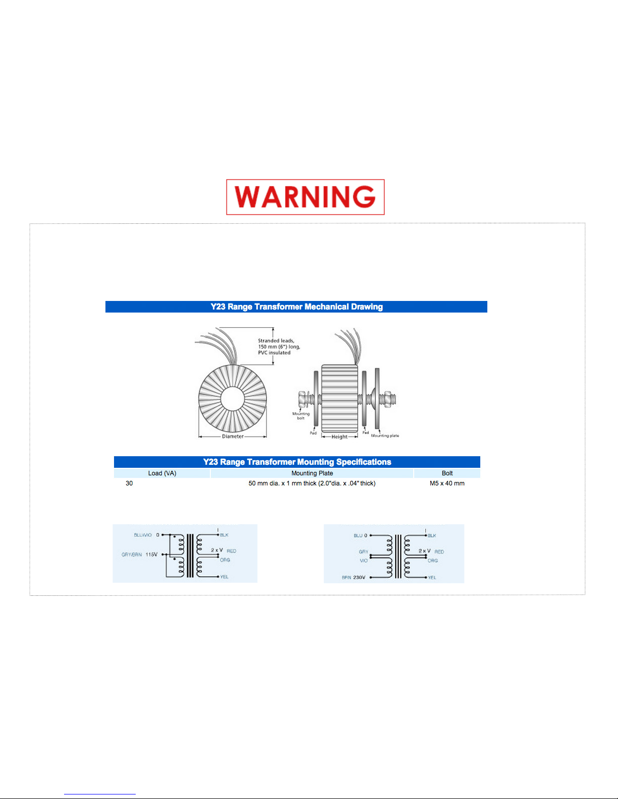
A POWER TRANSFORMER IS REQUIRED FOR PROPER OPERATION
DO NOT CONNECT THE PSU-2448PLUS+ KIT DIRECTLY TO AC MAIN LINES
The instructions on this page are for the FiveFish Audio PWR-TRAFO kit. If you are using a different power transformer
brand or model/part#, please consult your power transformer’s manufacturer’s documentation.
110Volt Wiring Guide 220Volt Wiring Guide
Page 7

Copyright © 2017 FiveFish AudioPSU-2448Plus+ Assembly Guide
2. TOOLS & EQUIPMENT REQUIRED
A few basic tools and equipment are required to assemble this kit. These basic tools are not supplied
with the kit.
2.1. Soldering Iron and Lead - We recommend a temperature adjustable soldering iron. DO NOT
USE A 100 WATT SOLDERING GUN. A small to medium-sized soldering tip is required to
solder the small parts. You may use lead-free or 60/40 lead-based solder.
2.2 Cutter - You will need a cutter to cut component leads and wires.
2.3. Solder Sucker Pump - If you need to desolder a component, you’ll need one.
2.4. Multitester - Used for measuring resistance, continuity, and voltages.
2.5. Magnier & Lamp - I recommend a clean and well-lighted space for your assembly area.
2.6. Other Tools (not required, but nice to have) - Component lead bender, vise, tweezers, wire
stripper.
Page 8
Copyright © 2017 FiveFish AudioPSU-2448Plus+ Assembly Guide
3. ASSEMBLY GUIDE
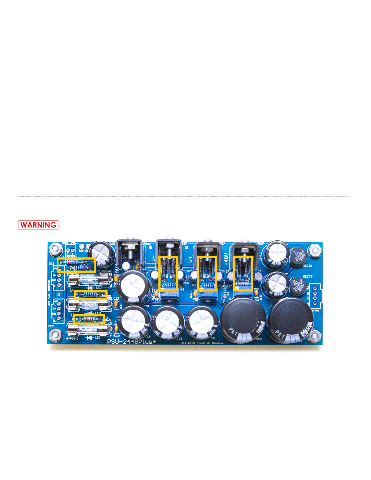
3.1 Solder all resistors and diodes.
Insert diodes in the correct orientation. Align the white band of diode with silkscreen on the PCB.
GENERAL INSTRUCTIONS: Open zip bag, insert component into board, solder.
All components are labeled in their own zip bags. There may be multiple components stored in each zip bag, with
their quantity noted. The voltage regulator part numbers (LM317, LM337) are marked on the device. Make sure to
insert each regulator into it’s correct location.
TIP: Solder smallest/shortest components rst before the larger/taller components to make assembly work easier.
Page 9
Copyright © 2017 FiveFish AudioPSU-2448Plus+ Assembly Guide
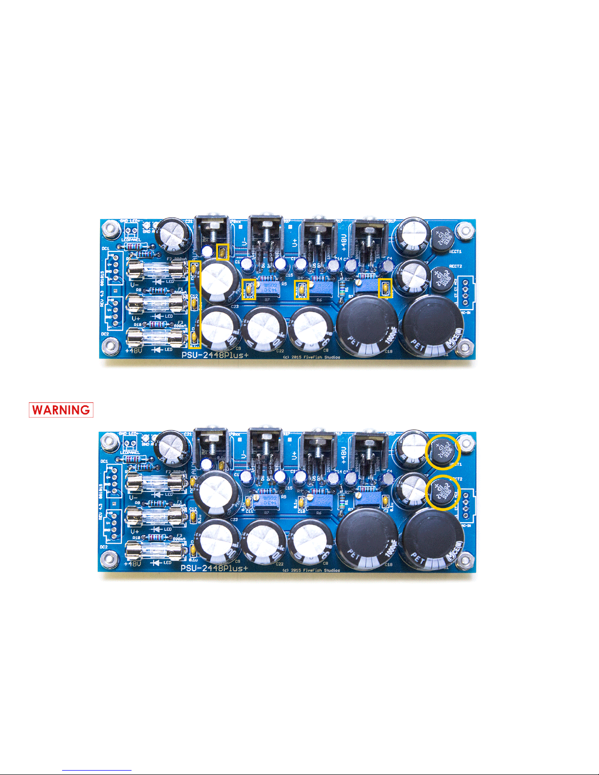
3.2 Solder all ceramic capacitors. These are the small yellow components.
3.3 Solder Bridge Rectiers.
The Bridge Rectiers may be damaged if you apply too much heat for a long period of time.
Page 10
Copyright © 2017 FiveFish AudioPSU-2448Plus+ Assembly Guide
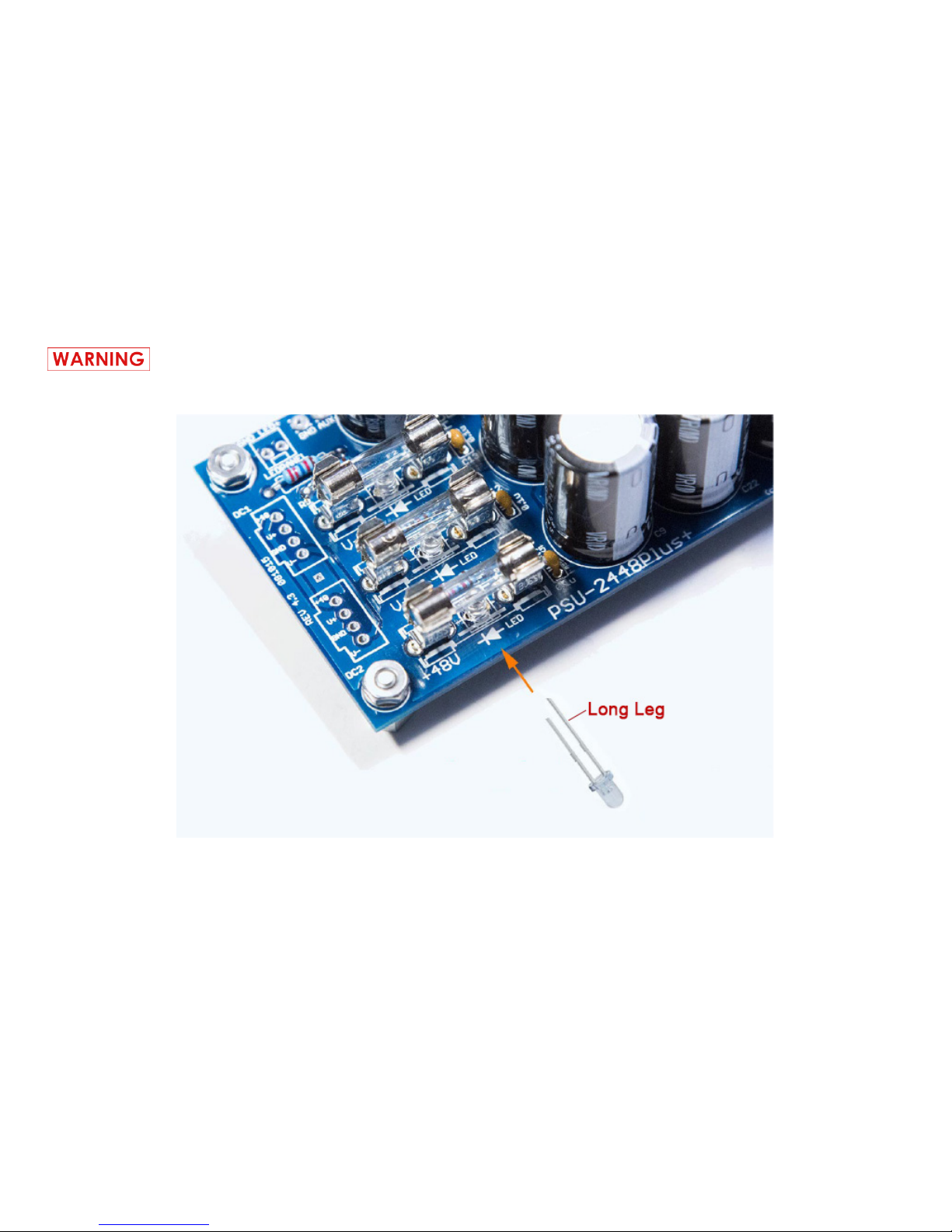
3.4 Solder the (3) Light Emitting Diodes (LED).
LEDs, like diodes, have polarity and must be inserted in the proper orientation. See additional
photos below for correct orientation.
Mount the LEDs as low as possible on the PCB so
it wouldn’t interfere when the fuses are installed.
Page 11
Copyright © 2017 FiveFish AudioPSU-2448Plus+ Assembly Guide
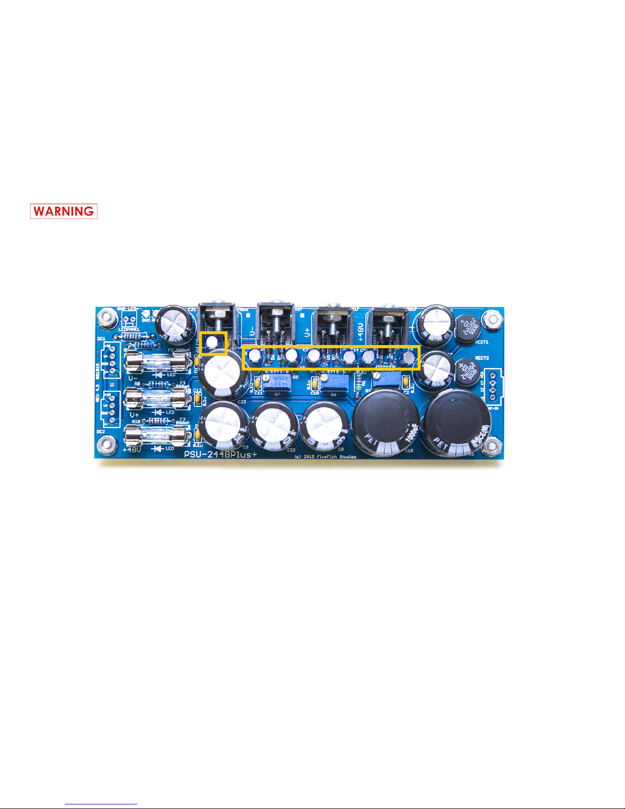
Electrolytic capacitors have polarity markings. One side is marked (-) negative, and the other side
is (+) positive. Insert the capacitors to the PCB following the correct polarity. NOTE: All capacitors
in the PSU kit are oriented in the same direction.
3.5 Solder all small electrolytic capacitors.
Page 12
Copyright © 2017 FiveFish AudioPSU-2448Plus+ Assembly Guide
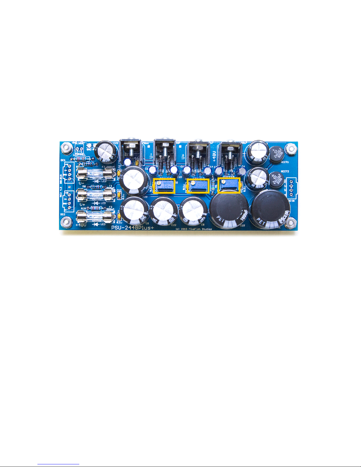
3.6 Solder all trimmer resistors. Trimmer resistors are used to adjust the nal output voltages of the Power Supply Unit.
Page 13
Copyright © 2017 FiveFish AudioPSU-2448Plus+ Assembly Guide
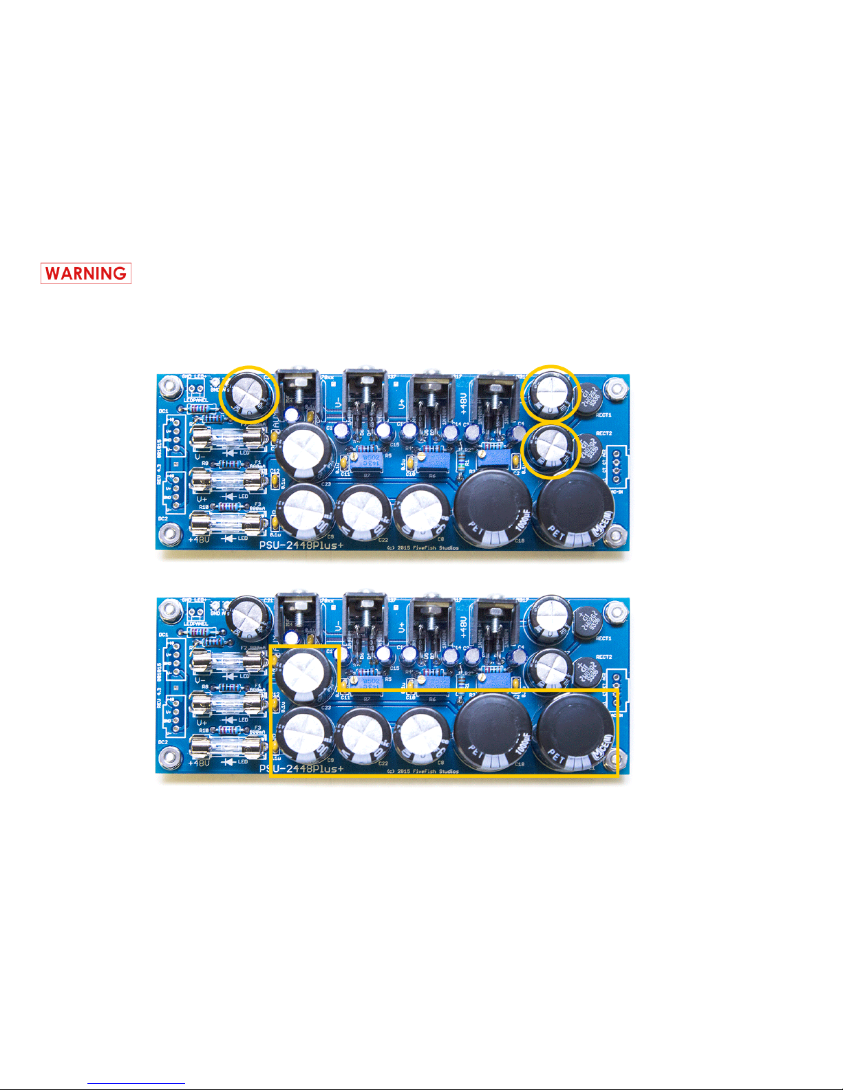
Electrolytic capacitors have polarity markings. One side is marked (-) negative, and the other side
is (+) positive. Insert the capacitors to the PCB following the correct polarity. NOTE: All capacitors
in the PSU kit are oriented in the same direction.
3.7 Solder all medium-sized electrolytic capacitors, then all large-sized electrolytic capacitors.
NOTE: The 1000uf/80V capacitors are twist-in type. Push them into the board with a rotating motion.
Page 14
Copyright © 2017 FiveFish AudioPSU-2448Plus+ Assembly Guide
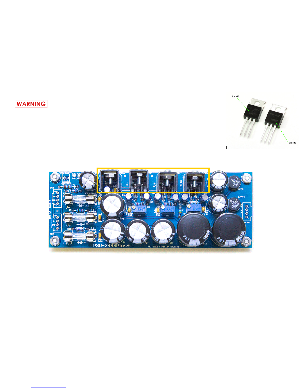
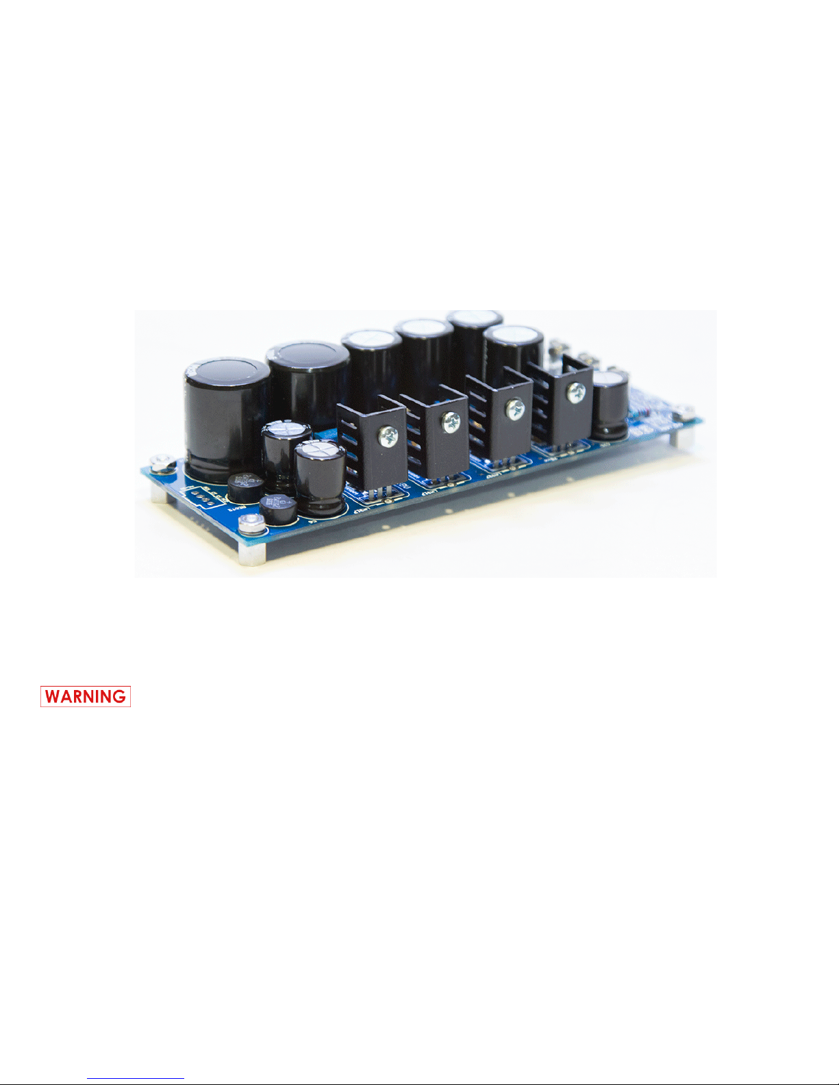
3.8 Solder the voltage regulators. The at-side/metal-side of the voltage regulator should be facing towards the
edge of the PCB.
For V+, and +48V section: Use the LM317HVT voltage regulator.
For V- section: Use the LM337 voltage regulator.
For the Vaux section: You may use any of the following -- 7805, 7812, 7815, or 7818 voltage
regulators for +5V, +12V, +15V, +18Volts respectively.
DO NOT INTERCHANGE THE POSITION OF THE VOLTAGE REGULATORS OR YOU
MAY DAMAGE THEM.
Page 15
Copyright © 2017 FiveFish AudioPSU-2448Plus+ Assembly Guide
NOTE: If you use the provided heatsinks, there is no need to use TO-220 MICA or SIL-PAD insulators.
If you need to operate this power supply at higher current, or experiencing high temperatures, you may need bigger heatsinks
than the ones provided in the kit. Please read note below:
If you want to use a single or common heatsink for all voltage regulators (for example: metal chassis case, or a
big aluminum n-type heatsink, you need to use MICA or SIL-PAD insulators and check that the regulator tab is
electrically isolated from your aluminum or metal heatsink. Failure to electrically isolate the metal tab from
your common heatsink will result in a short-circuit and damage to your voltage regulators.
3.9 Attach the provided heatsinks to the voltage regulators.
Page 16
Copyright © 2017 FiveFish AudioPSU-2448Plus+ Assembly Guide
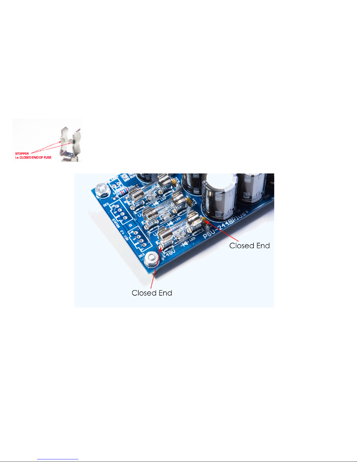
NOTE: The fuses are provided for short-circuit and overload protection. If an accidental short-circuit occured, the fuse will blow
“open” before any permanent damage is done to the voltage regulators. While the regulators have built-in short-circuit protection,
we think the fuses offer additional protection and will be much more convenient for the end-user to replace than a damage voltage
regulator.
3.10 Solder the (6) fuse clips. After soldering the fuse clips, insert the (3) fuses into the fuse holders.
NOTE: Observe the proper orientation of the fuse clip. One side has a “stopper” and the other side
is completely open. The “stopper” side should be positioned at the outside edges (so the glass fuse
cartridge can be inserted properly).
Page 17
Copyright © 2017 FiveFish AudioPSU-2448Plus+ Assembly Guide
4. WIRING GUIDE
4.1 AC Input (from Power Transformer Secondary)
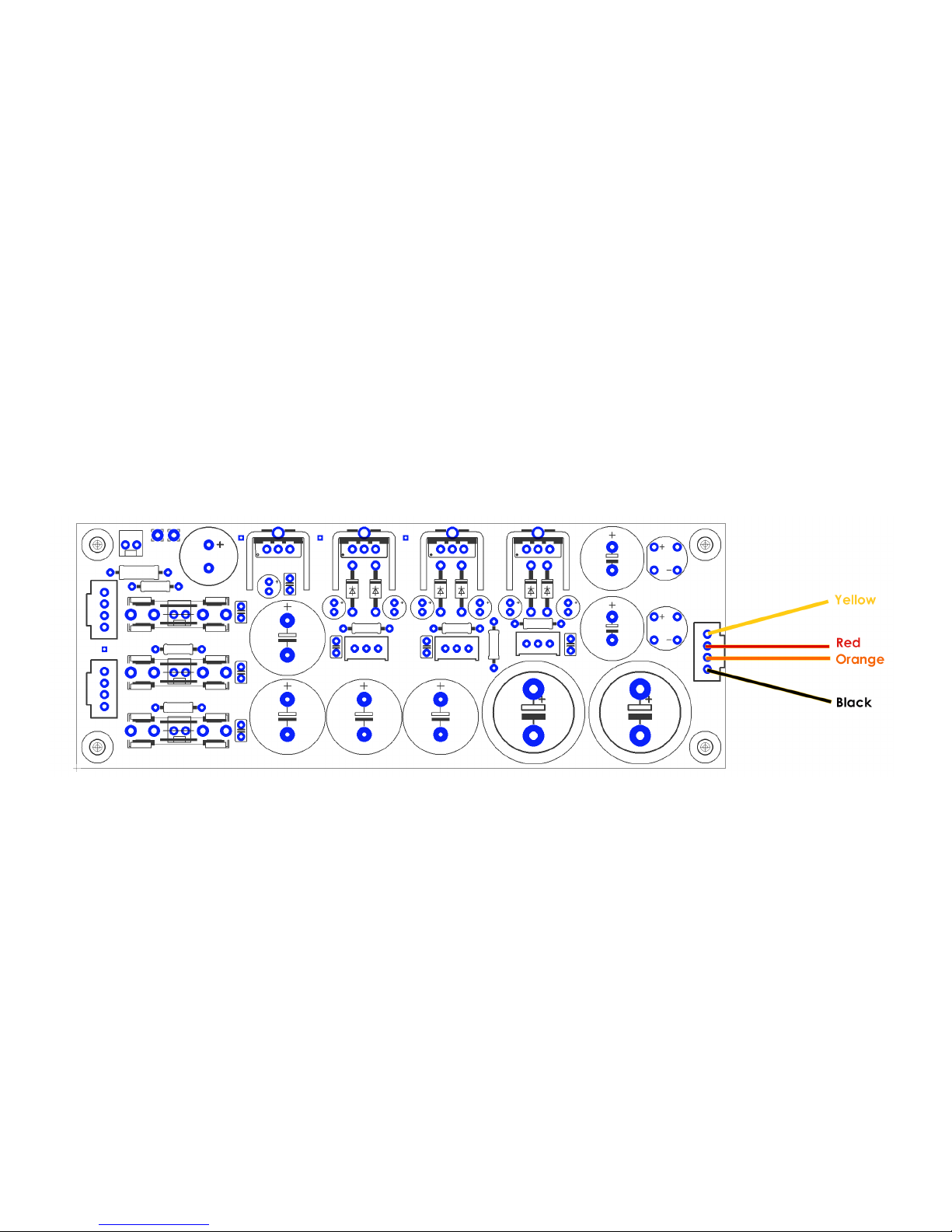
Connect the Power Supply Board to the power transformer secondary windings. Use the following wiring guide. Colors
refer to the transformer secondary winding wire colors.
NOTE: Red and Orange wires are connected together at the PSU Board. You can interchange the Yellow/Black wire
locations, since we’re dealing with AC voltages and there is no polarity.
The PSU kit uses standard 0.1” pitch pads for all
input and output connections. You can use standard
0.1” Molex headers to make connections.
Page 18
Copyright © 2017 FiveFish AudioPSU-2448Plus+ Assembly Guide
4.2 DC Output
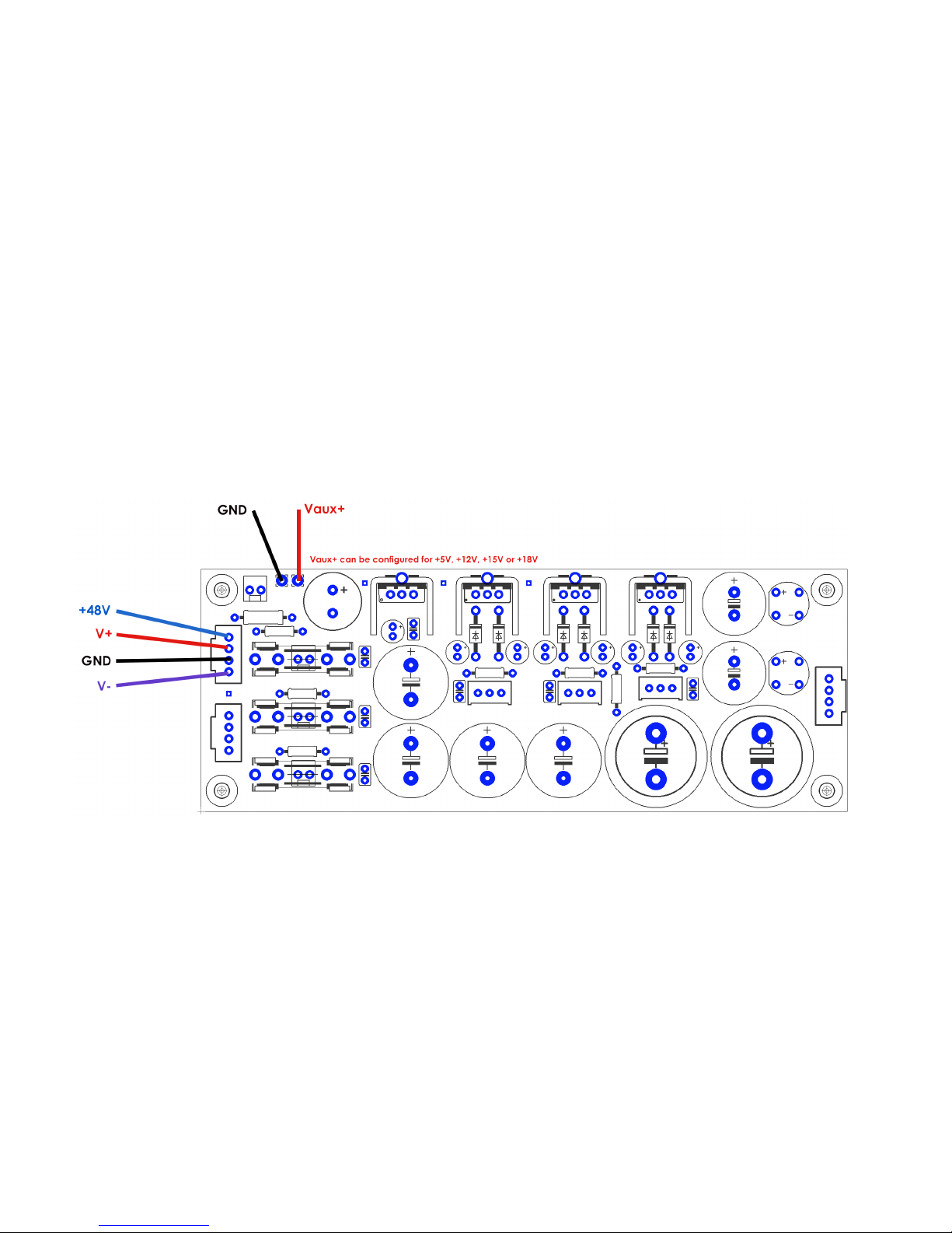
There are (2) power ports available on the PSU board. They are identical and the same.
Vaux+ output can be congured by using the appropriate voltage regulator part# for IC4 location.
+ 5V -- 7805 Voltage Regulator in IC4 location
+12V -- 7812 Voltage Regulator in IC4 location
+15V -- 7815 Voltage Regulator in IC4 location
+18V -- 7818 Voltage Regulator in IC4 location
Page 19
Copyright © 2017 FiveFish AudioPSU-2448Plus+ Assembly Guide
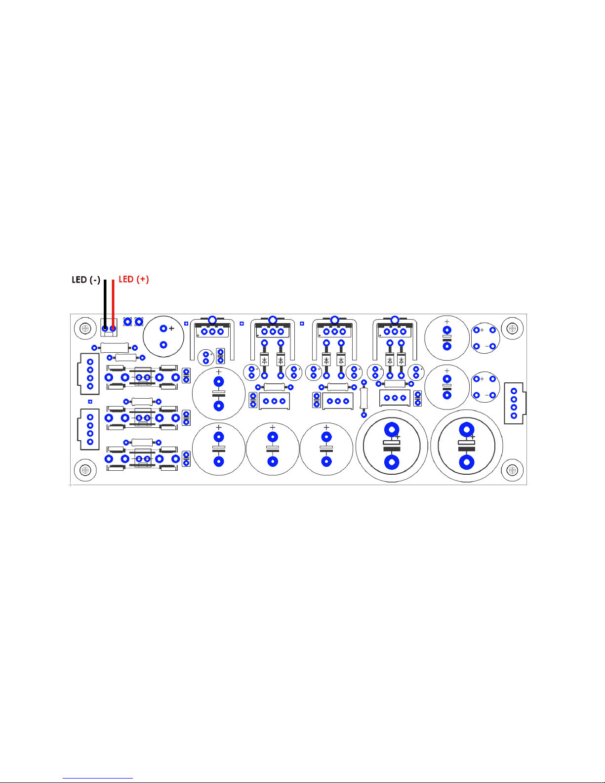
4.3 Panel LED
For your convenience, solder pads are provided for wiring to a Panel LED to indicate Power ON. You may replace the
resistor behind the LED headers if you need more/less current for your chosen LED indicator. The supply voltage is 48V.
Compute for the appropriate value of R using the formula R = V x I ; where I is the current required for LED illumination.
Page 20
Copyright © 2017 FiveFish AudioPSU-2448Plus+ Assembly Guide
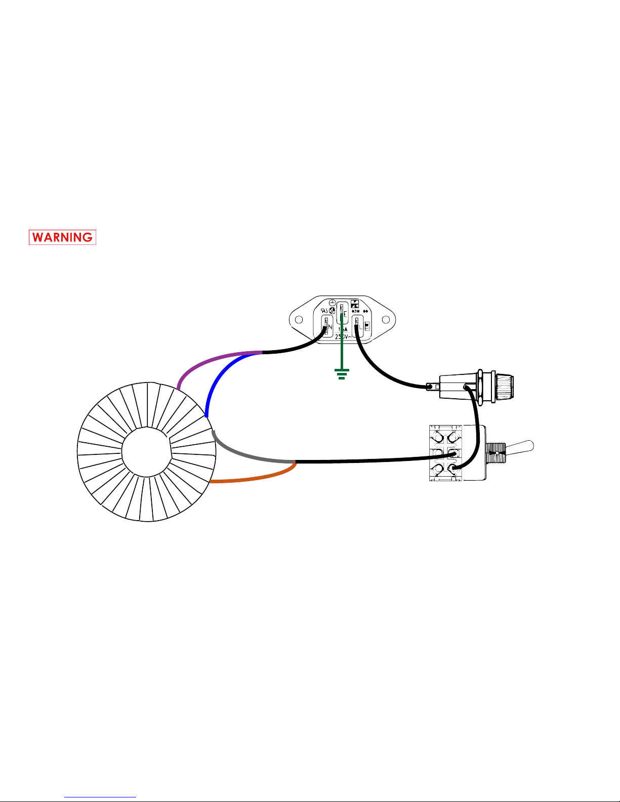
4.4 Power Transformer Primary / High Voltage AC Wiring Guide
If you are not comfortable following this step, please hire a professional electrician to complete this section.
You will be working with high-voltage AC mains line. Depending on your location, this may be 110Volts or
220Volts. These voltages can seriously injure or kill and I strongly suggest following all safety precautions.
AC INPUT
FUSE HOLDER
SAFETY
GROUND
POWER TRANSFORMER
VIOLET
BLUE
GRAY
BROWN
110 VOLT WIRING GUIDE
POWER SWITCH
For 220V Wiring Guide, refer to page 6 of this assembly guide.
Page 21

Copyright © 2017 FiveFish AudioPSU-2448Plus+ Assembly Guide
5. ADJUSTMENT AND CALIBRATION GUIDE
Equipment Required:
Multimeter or Voltmeter
Test Leads or Probe
5.1 Adjustment procedure for +48V output
Set multimeter to DC Volts reading.
Connect multimeter (+) probe lead to DC1-pad1 (labeled +48V).
Connect multimeter (-) probe lead to DC1-pad3 (labeled GND).
Adjust R3 trimmer until you get a reading of +48 Volts.
5.2 Adjustment procedure for V+ output
Set multimeter to DC Volts reading.
Connect multimeter (+) probe lead to DC1-pad2 (labeled V+).
Connect multimeter (-) probe lead to DC1-pad3 (labeled GND).
Adjust R6 trimmer for your desired output voltage.
5.3 Adjustment procedure for V- output
Set multimeter to DC Volts reading.
Connect multimeter (+) probe lead to DC1-pad4 (labeled V-).
Connect multimeter (-) probe lead to DC1-pad3 (labeled GND).
Adjust R7 trimmer for your desired output voltage.
Note: Polarity will be reversed and you will get a negative voltage reading.
5.4 Fixed Output - Vaux
Vaux is a xed voltage output. Use the table
below to set the xed output voltage you want
by using the appropriate part# for IC4.
Vaux Output IC4 Part#
+5V 7805
+12V 7812
+15V 7815
+18V 7818
NOTE: V+ output must be greater than Vaux.
Page 22

Copyright © 2017 FiveFish AudioPSU-2448Plus+ Assembly Guide
6. TROUBLESHOOTING GUIDE
6.1 Adjusting the trimmers do not change the output voltage.
Check for open connection, or cold-solder joints.
6.2 The output voltages are at maximum reading. Adjusting the trimmer does not lower the voltages.
It seems the voltage regulators are not working/damaged. Damage could have been caused by a short-circuit. Check
solder job for any shorts. Replace damaged voltage regulator for the particular section (V+, V-, +48V).
6.3 Power Supply was previously working. But now there is no output voltage for V+ / V- / or +48V.
Check if the fuse is blown. Check if LED is lit up below the fuse. If the LED is OFF, then that particular fuse is broken.
Replace fuse with a new one. If the replacement fuse blows open again, you have a short-circuit somewhere... either
down the line/load, or in the PSU. Remove offending short-circuit.
6.4 No output voltage. Fuse is blowing open.
Check orientation of all the diodes if they are placed correctly. A diode in the wrong direction will cause a short circuit
in the PSU output.
6.5 V+ and V- sections are working but the +48V section is not working, no output voltage.
Check C6 and C7 capacitor. Check if RECT1 Bridge Rectier is working by checking for presence of DC volts across
capacitor C1. If there is DC voltage across C1, but no output voltage, then IC1 voltage regulator is damaged/open.
Replace IC1 with LM317HVT.
Page 23

Copyright © 2017 FiveFish AudioPSU-2448Plus+ Assembly Guide
is page intentionally le blank.
Page 24

Copyright © 2017 FiveFish AudioPSU-2448Plus+ Assembly Guide
7. PARTS LIST
QTY VALUE REFERENCE NOTE
1 3K57 R1
3 220 ohm R2, R4, R5
3 5K Trimmer R3, R6, R7 Voltage Adjustments
2 10K R8, R9
1 22K6 R10
1 22K6 LEDPANEL Resistor for Panel Mount LED
7 10uf 63V C3, C4, C14, C15, C16, C17, C19
7 0.1uf 100V C2, C5, C10, C11, C12, C13, C20
3 100uf 100V C6, C7, C21
4 1000uf 63V C8, C9, C22, C23
2 1000uf 80V C1, C18 Snap-in type Capacitors
2 LM317HVT IC1, IC2 Positive Voltage Regulator
1 LM337 IC3 Negative Voltage Regulator
1 78xx IC4 (not included) Use either 7805, 7812, 7815, 7818
2 W02M RECT1, RECT2 Bridge Rectier
6 1N4004 D1, D2, D3, D4, D5, D6 Protection Diodes
3 LED LED1, LED2, LED3 Light Emitting Diode
1 Panel Mount LED LED4 Not included in this kit but in PWR-TRAFO KIT
4 Heatsink HS1, HS2, HS3, HS4 Black Anodized Aluminum Heatsink
6 Fuse Clips Fuse Clips 3 pairs of Fuse Clips
3 Fuse F1, F2, F3
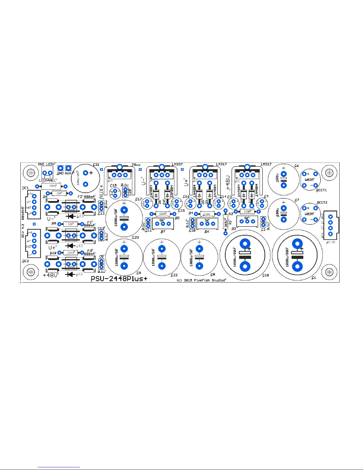
See Section 8.0 for component locations on PCB.
Page 25
Copyright © 2017 FiveFish AudioPSU-2448Plus+ Assembly Guide
8. COMPONENT GUIDE
Page 26
Copyright © 2017 FiveFish AudioPSU-2448Plus+ Assembly Guide
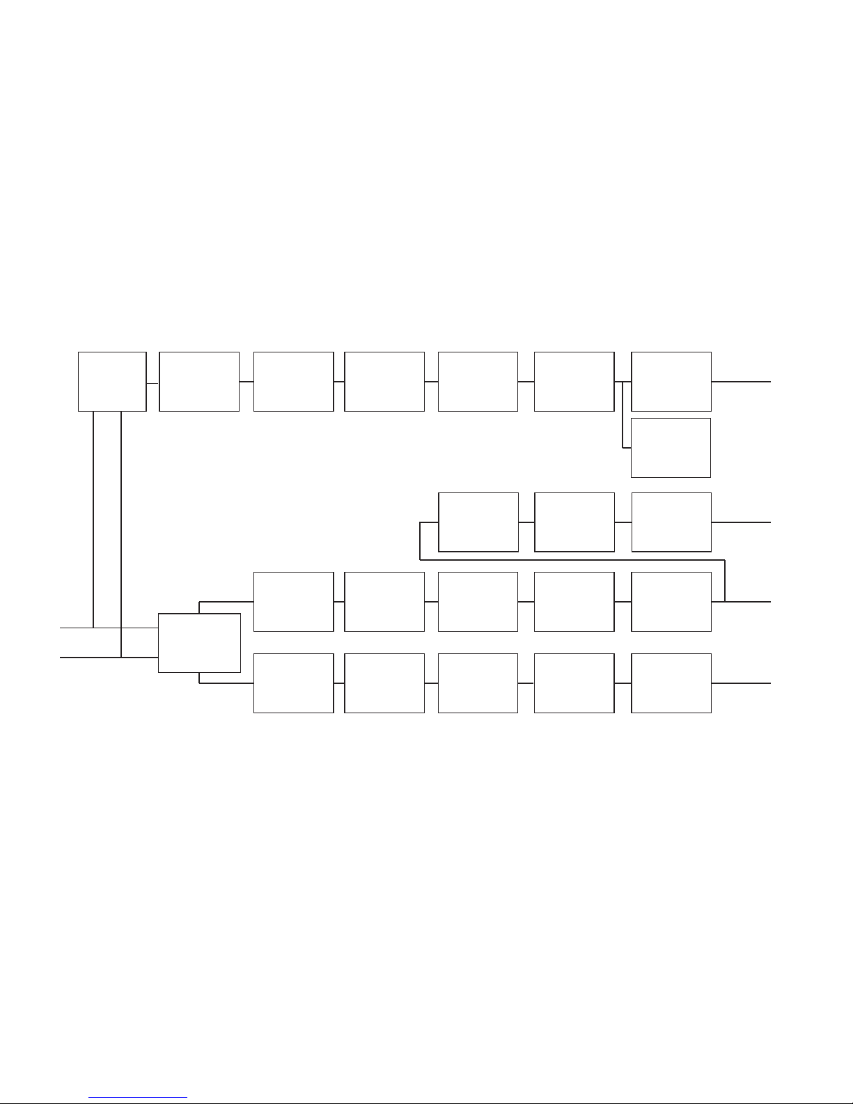
9. BLOCK DIAGRAM
AC Coupling
Bridge Rectier
Bridge Rectier
DC Filtering
(+) Adjustable
Voltage
Regulator
DC Filtering
Fuse Protection LED Indicator
Panel LED
Indicator
DC Filtering
(+) Adjustable
Voltage
Regulator
DC Filtering
Fuse Protection LED Indicator
DC Filtering
(-) Adjustable
Voltage
Regulator
DC Filtering
Fuse Protection LED Indicator
AC
AC
+48V
V+
V-
DC Filtering
(+) Fixed
Voltage
Regulator
DC Filtering
Vaux
NOTE: The AC voltage depicted in block diagram above comes from the low-voltage secondary winding of the power transformer.
Page 27
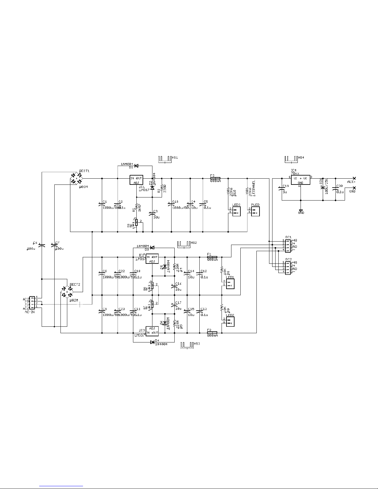
Copyright © 2017 FiveFish AudioPSU-2448Plus+ Assembly Guide
10. SCHEMATIC DIAGRAM
Page 28

Copyright © 2017 FiveFish AudioPSU-2448Plus+ Assembly Guide
11. ERRATA / MANUAL CHANGE INFORMATION
Any corrections, changes, modications, improvements to this product will be listed on this page.
 Loading...