

Page 1

FiveFish
Studios
VT-73 Hybrid-Tube Mic Preamp Kit
Assembly Guide
Copyright © 2015 FiveFish Audio
Page 2
No part of this document may be reproduced, either mechanically or electronically, posted online on the Internet,
in whole or in part, without the expressed, written permission of FiveFish Audio. This document is solely provided
to the kit builder of the VT-73 Hybrid-Tube Mic Preamp.
Copyright © 2017 FiveFish Audio
veshaudio.com
Assembly Guide Revision 1.2 - 201760804
Page 3

Dear Customer,
ank you for purchasing our VT-73 Hybrid Tube Mic Preamp Kit.
Great care has been taken to make this assembly guide complete and as accurate as possible.
Our goal is to make your assembly work easy and trouble-free, and deliver to you a working,
reliable, and high-performance mic preamplier.
is assembly guide is a work in progress and we’re continually working to improve it. As
always, we welcome the input of the DIY community if you have any comments, suggestions,
or additional information that you think will be helpful for inclusion in this assembly guide.
If you have any questions that are not covered by this assembly guide, please feel free to
contact us at www.veshaudio.com, or via our facebook page.
Sincerely,
FiveFish Team
FiveFish
Studios
FiveFish Audio
www.veshaudio.com
Page 4

Copyright © 2017 FiveFish AudioVT-73 Hybrid Tube Mic Preamp Assembly Guide
GENERAL
This assembly guide must be reviewed for familiarization
with safety markings and instructions before assembly of
the Mic Preamp kit.
BEFORE APPLYING POWER
Verify that all components and parts are inserted in the
right location and correct orientation. Visually inspect
that there are no cold solder joints, or short-circuits.
The WARNING sign denotes a hazard. Pay attention
to the procedure, instructions, or the like, which if not
correctly performed could result in damage to your
equipment, electronic component or personal injury.
SAFETY CONSIDERATIONS
Any interruption or disconnection, or lack of connection of
the protective earth terminal/safety ground may cause a
potential electric shock hazard that could result in personal
injury. (Grounding one conductor of a two conductor outlet
is not sufcient protection).
This mic preamp module is designed to be plug-in into
an API 500 series rack or compatible unit. DC Power is
supplied by the 500 series rack to this module.
It is strongly suggested that you use a lab power supply
the rst-time you power your mic preamp project. If
you made any mistake during assembly of this kit (for
example: components inserted in wrong location, wrong
orientation, short-circuit in your soldering job, etc.) you will
not be subjecting the built-in power supply of your rack
to the problem, and avoid damaging your power supply.
If you don’t have a lab power supply and instead will be
using your rack to power directly this project the rst time,
I recommend using an extender card with built-in fuses
to protect your rack power supply from accidental shorts
or over-current. (The in-line fuses will blow if there is
overcurrent or short-circuit condition, thus protecting the
rack power supply).
Page 5

Copyright © 2017 FiveFish AudioVT-73 Hybrid Tube Mic Preamp Assembly Guide
GENERAL INFORMATION
1. DESCRIPTION
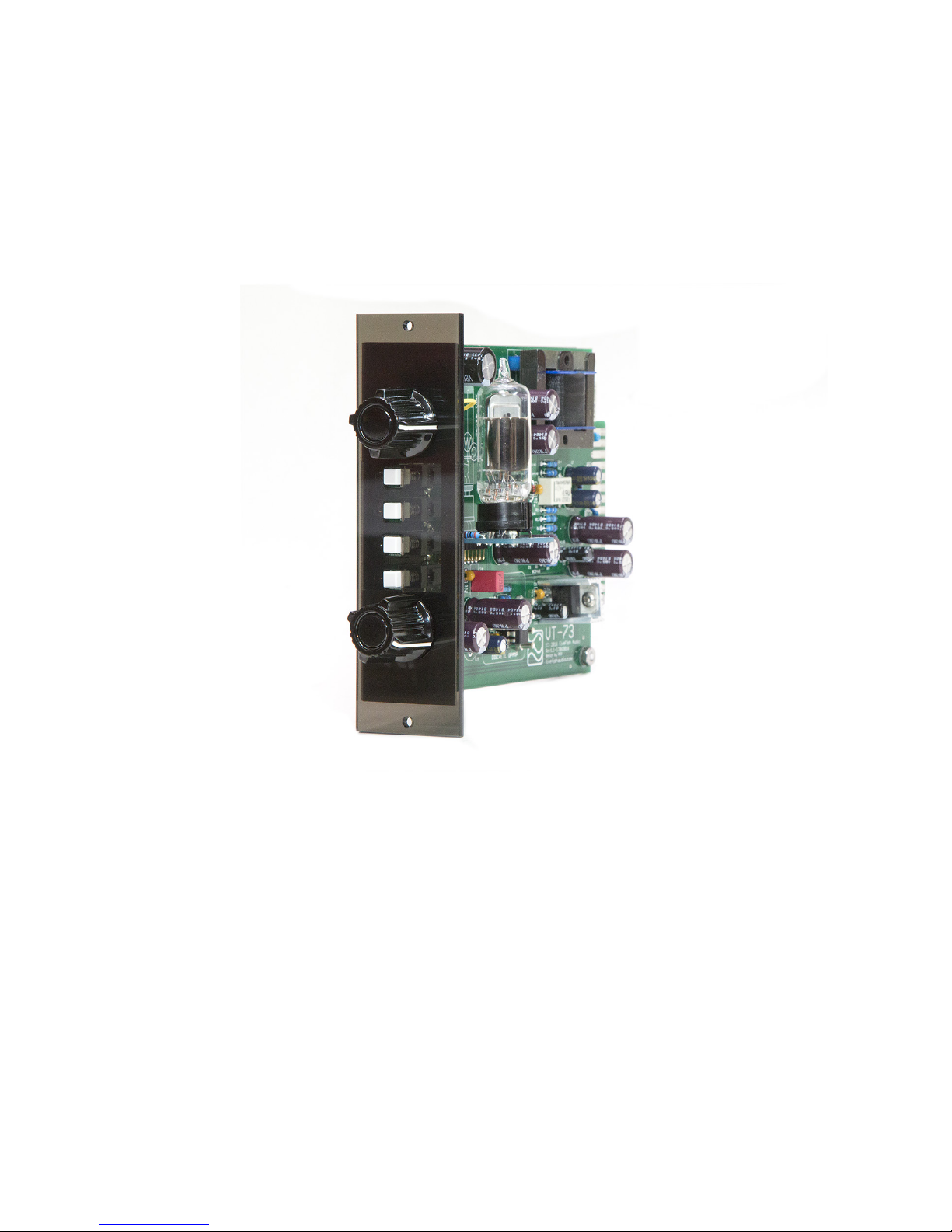
The VT-73 Mic Preamp Kit is a Hybrid Solid-State/Vacuum Tube mic preamp designed for use with API 500 Series lunchboxes or
racks.
The VT-73 design uses a high-performance THAT amplier chip as the primary First Stage amplier. This allows us to have a very
quiet, balanced input front end without the need for an Input Transformer. Voltage gain for the First Stage is set using a single-turn
potentiometer to allow for a wide and continuous range of dB gain. There is also RFI input and output protection and built-in 48V
short-circuit protection to protect the preamp from damage.
The output of the First Stage is fed to the Second Stage Tube amplier, for additional signal processing. This Second Stage also
generates the Second-Order Harmonics added to our original signal. Second Stage output is controlled by a second potentiometer
that can limit the output level of the Mic Preamp. A Third Stage amplier allows for an optional +12dB Signal Boost, and also drives
our Output Transformer for a Balanced Output.
The VT-73 uses separate push-button switches for 48V Phantom Power, -20dB Pad, Polarity Reverse, and Gain Boost. The kit
builder can also wire optional 3mm LED indicators for each switch to indicate when the function is enabled.
The VT-73 requires a dual power supply (+/-15V to +/-18 Volts) and +48Volts for phantom power for proper operation.
Page 6

Copyright © 2017 FiveFish AudioVT-73 Hybrid Tube Mic Preamp Assembly Guide
2. TOOLS & EQUIPMENT REQUIRED
A few basic tools and equipment are required to assemble this kit. These basic tools are not supplied with the kit.
2.1. Soldering Iron and Lead - We recommend a temperature adjustable soldering iron. DO NOT USE A 100 WATT
SOLDERING GUN. A small to medium-sized soldering tip is required to solder the small parts. You may use Lead-free or
60/40 lead-based solder.
2.2 Cutter - You will need a cutter to cut component leads and wires.
2.3. Solder Sucker Pump - If you made a mistake and need to desolder a component, you’ll need one.
2.4. Multitester - Used for measuring resistance, continuity, and voltages.
2.5. Magnier & Lamp - I recommend a clean and well-lighted space for your assembly area.
2.6. Other Tools (not required, but nice to have) - Component lead bender, vise, tweezers, wire stripper.
Page 7
Copyright © 2017 FiveFish AudioVT-73 Hybrid Tube Mic Preamp Assembly Guide
3. ASSEMBLY GUIDE
BEFORE YOU BEGIN: Pick a clean work area where you can leave your work-in-progress unattended if you need to.
Keep individual components in their labeled zip bag until you’re ready to solder them. Kit components have been sorted and
labeled for your convenience. The labeled components lessens chances of insertion errors, inserting the wrong component into
the wrong location. Keeping the components in their zip bags also reduces chance of small parts getting lost or misplaced.
Best practice is to solder the smallest and/or shortest components rst. Then solder the taller and larger components next. Big
bulkier components like switches, jacks, big capacitors are soldered last.
NOTE: The photos shown on this assembly guide are Rev.1.1 PCBs.
Your PCB Revision may be later but assembly instructions are
generally the same.
There are ERRATA corrections for the Rev 1.1 PCB version.
Please visit Section 4.0 for details.
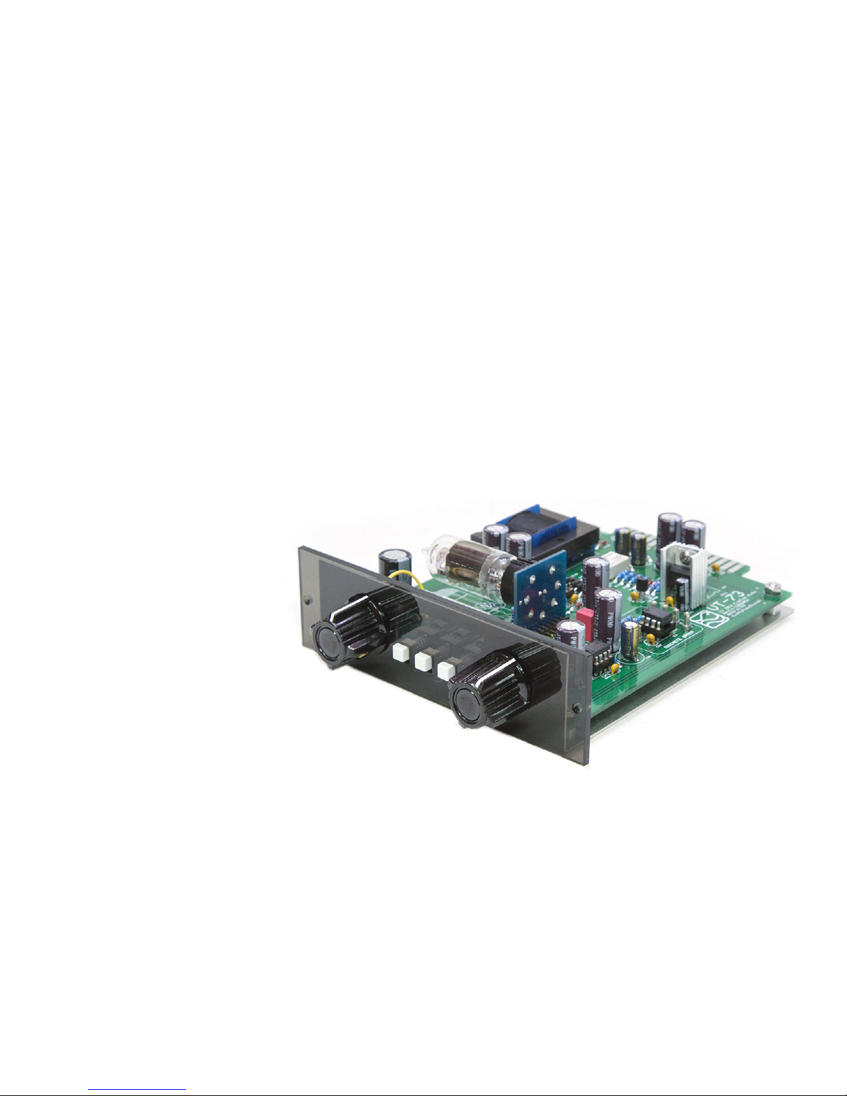
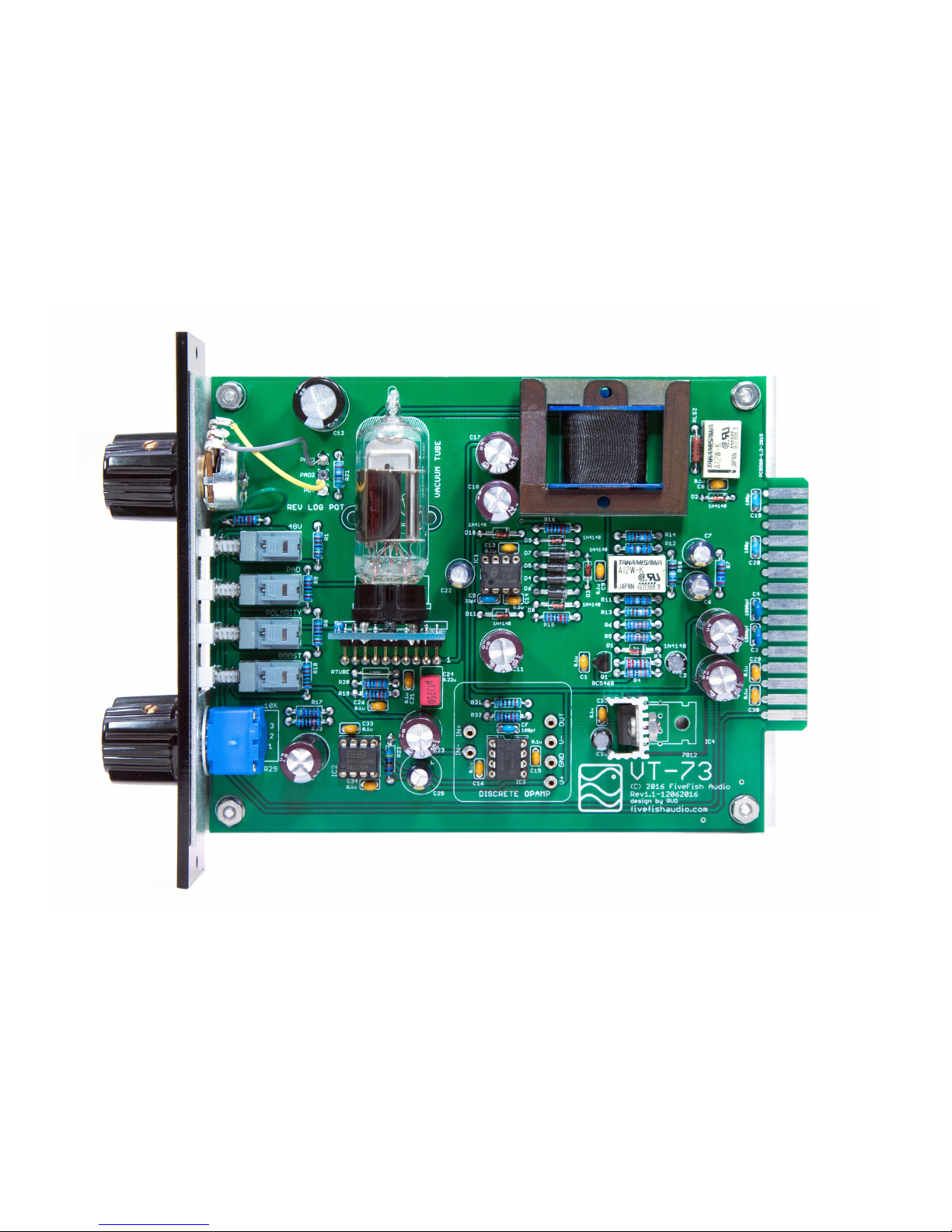
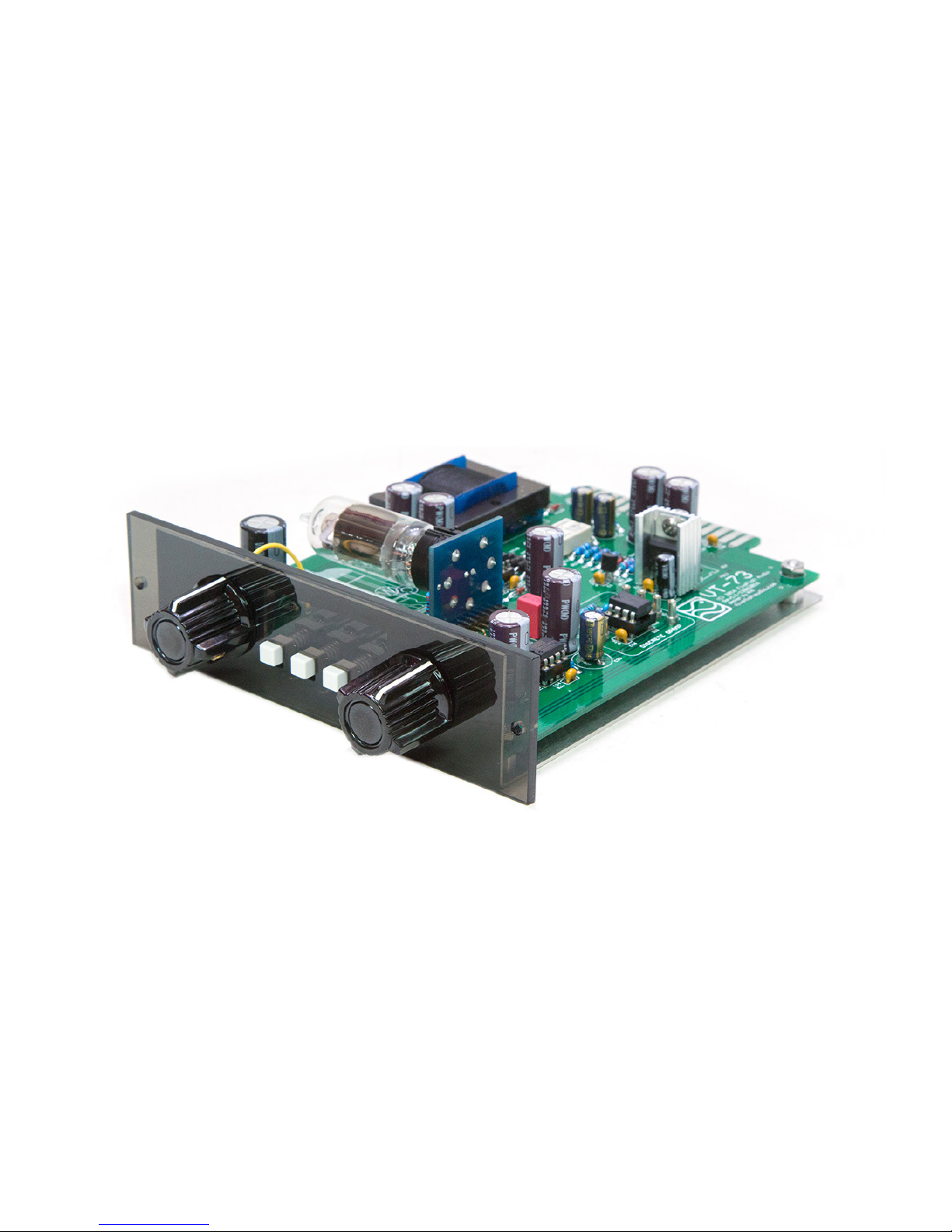
Photo of a nished VT-73 Mic Preamp
Page 8
Copyright © 2017 FiveFish AudioVT-73 Hybrid Tube Mic Preamp Assembly Guide
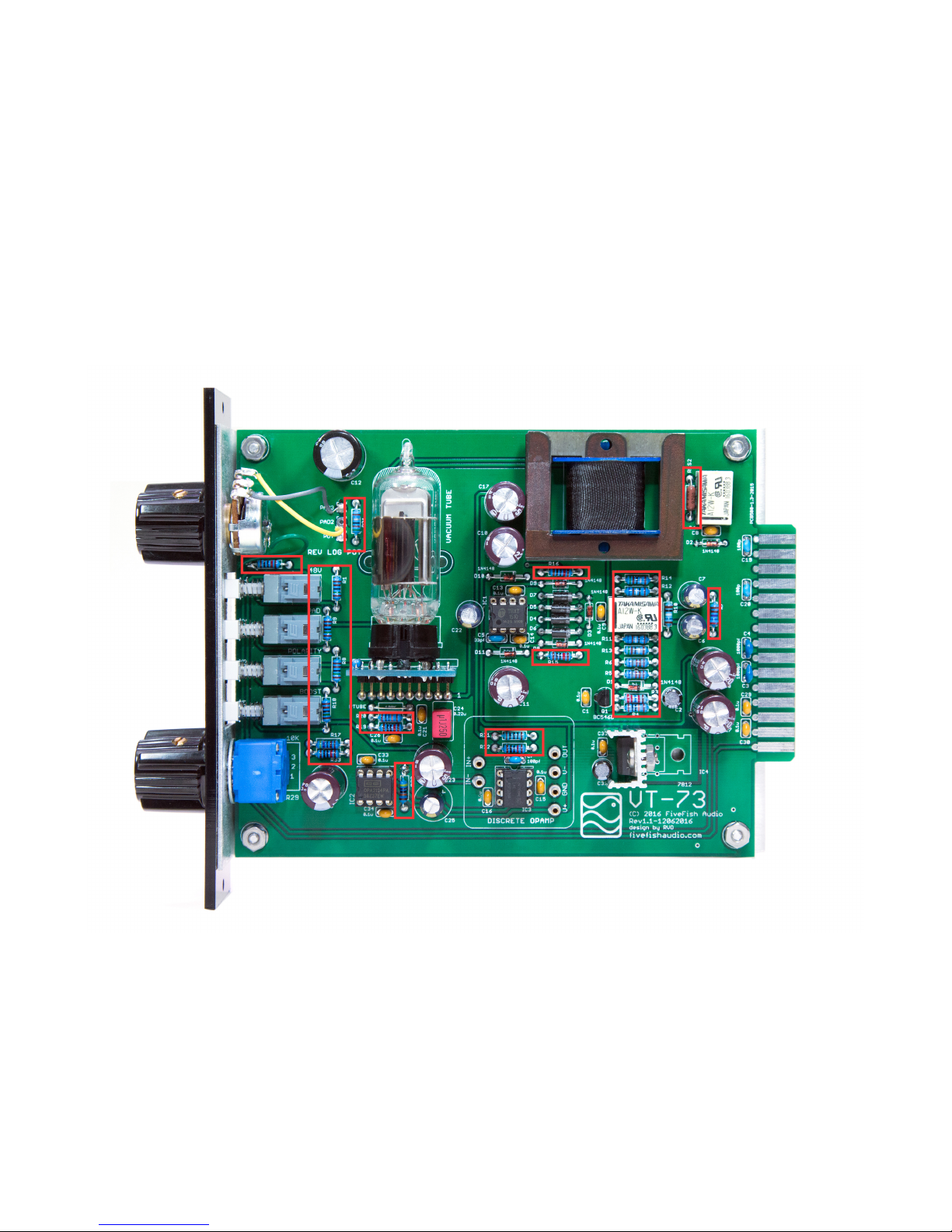
3.1 Solder all 1/4 watt Resistors.
ERRATA: Solder a jumper wire across RTUBE resistor location.
See Section 4.0 for other ERRATA corrections (R20, R21, R22)
Page 9
Copyright © 2017 FiveFish AudioVT-73 Hybrid Tube Mic Preamp Assembly Guide
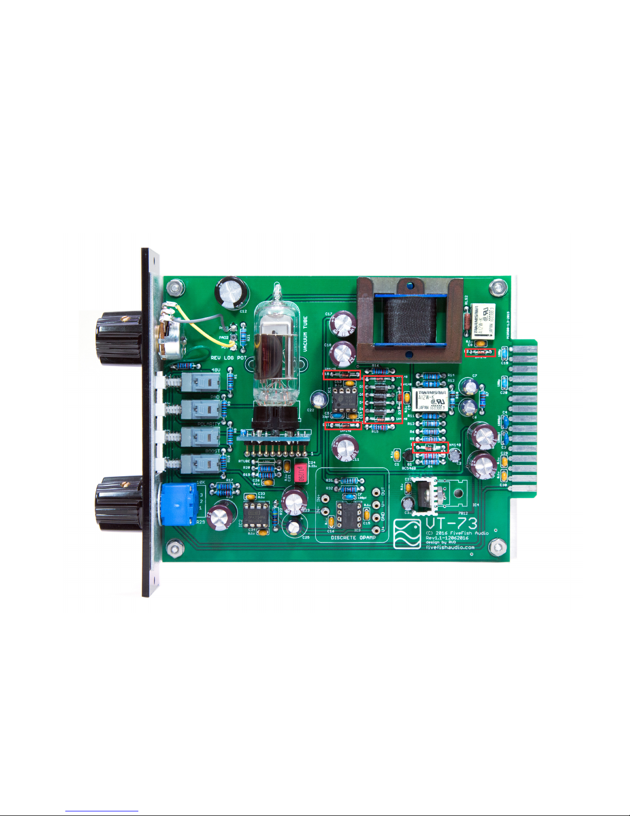
3.2 Solder all Signal Diodes and Rectier Diodes.
IMPORTANT: Diodes must be installed in the correct orientation. Observe where the “white band” is located on the board
silkscreen marking, and orient the Diodes to follow the same direction.
Page 10
Copyright © 2017 FiveFish AudioVT-73 Hybrid Tube Mic Preamp Assembly Guide
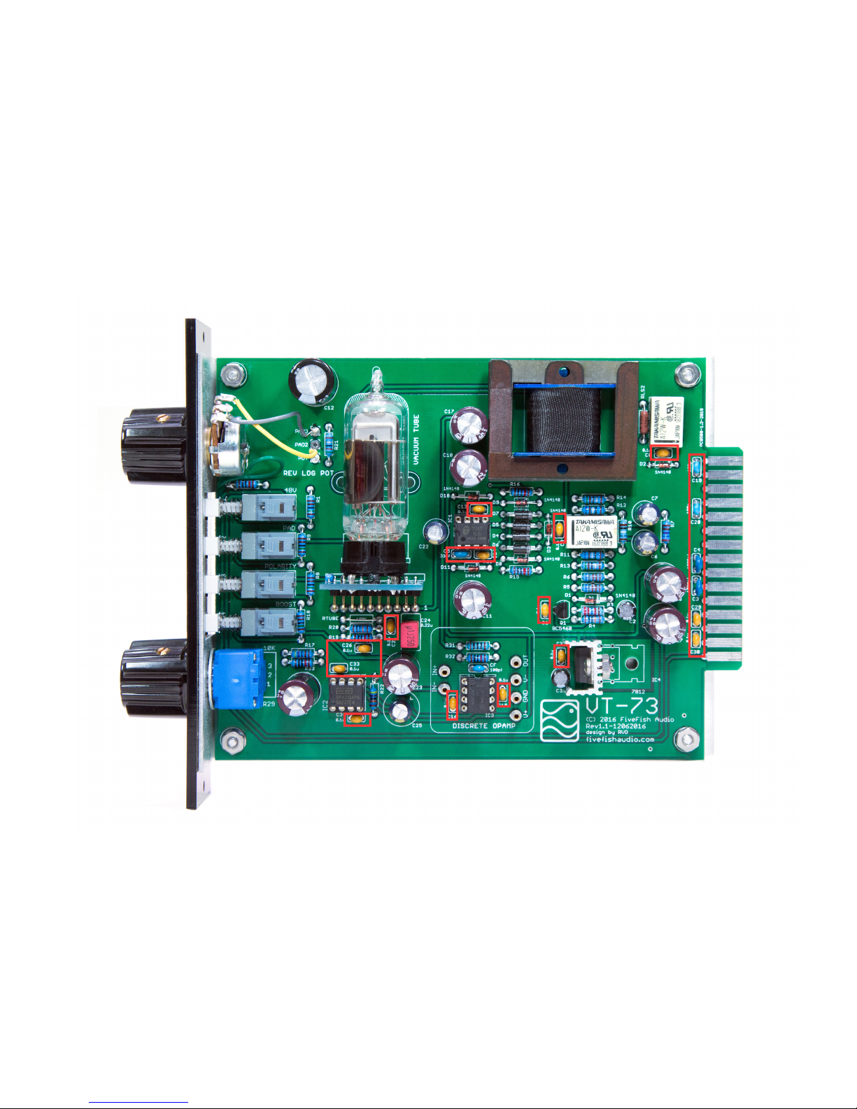
3.3 Solder all Ceramic capacitors.
Page 11
Copyright © 2017 FiveFish AudioVT-73 Hybrid Tube Mic Preamp Assembly Guide
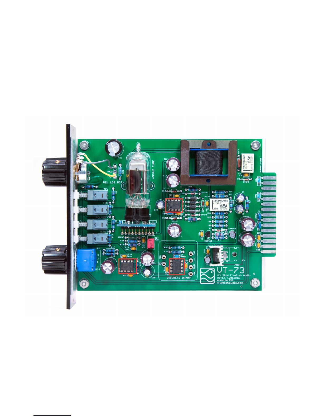
3.4 Solder the (3) IC Sockets.
TIP: One side of the IC socket will have a notch. Position this notch on the left-side, or on top for use as a guide for Pin1
location.
Page 12
Copyright © 2017 FiveFish AudioVT-73 Hybrid Tube Mic Preamp Assembly Guide
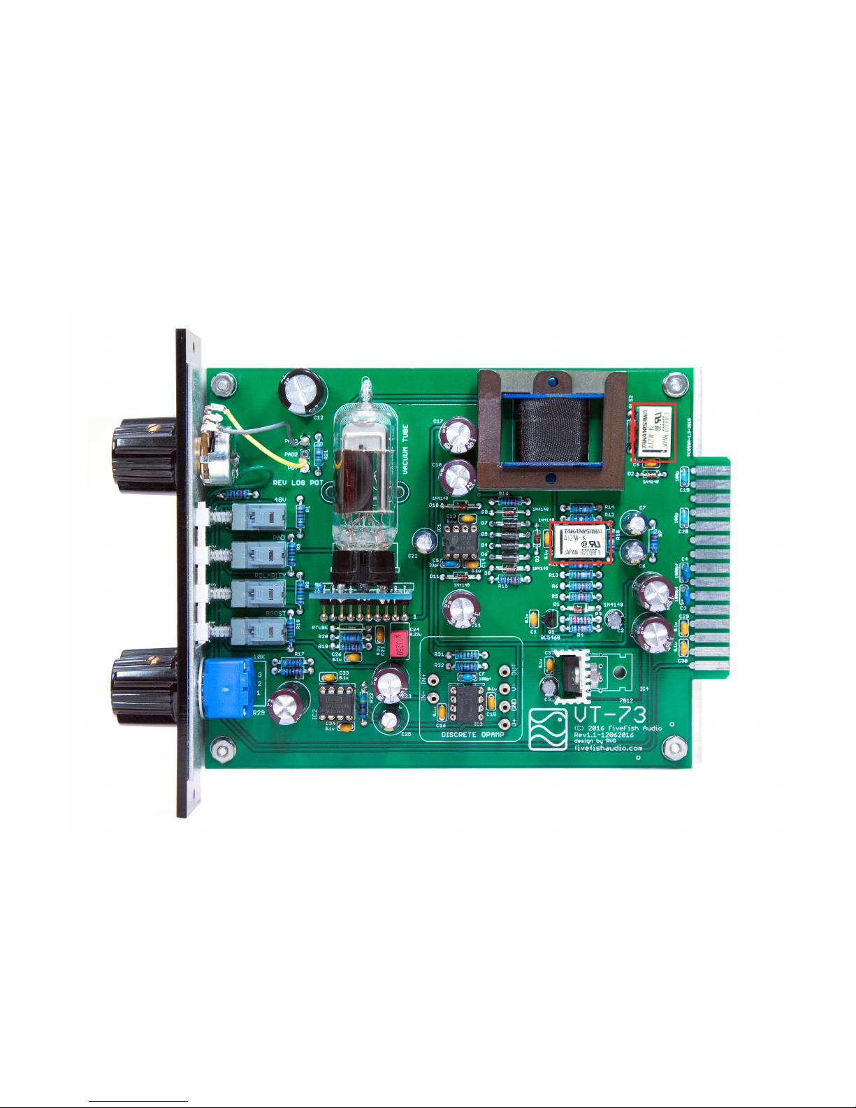
3.5 Solder the (2) PDIP Relays. Take note of the Relay part number that came with your kit and follow the next step.
IMPORTANT: Insert Relays in proper orientation. Match the “white band” on PCB silkscreen with the Relay’s line markings.
Page 13
Copyright © 2017 FiveFish AudioVT-73 Hybrid Tube Mic Preamp Assembly Guide
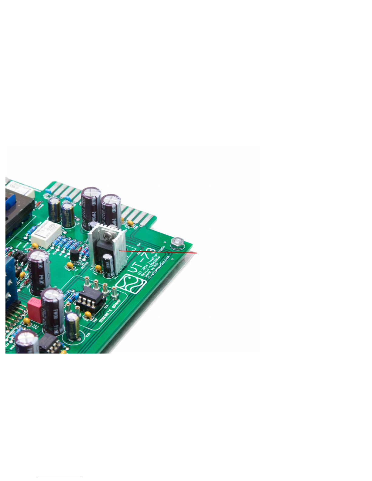
If your kit came with A12W-K Relays, solder the 7812
Voltage Regulator at IC4 location. You can use the heatsink
provided and mount it vertically, or bend the legs and
secure 7812 metal tab with machine screw and nut at on
the PCB board.
If your kit came with A18W-K Relays, Do NOT install the
7812 Voltage Regulator. Instead, solder a JUMPER wire
across pin 1 and pin 3 of IC4 location.
Page 14
Copyright © 2017 FiveFish AudioVT-73 Hybrid Tube Mic Preamp Assembly Guide
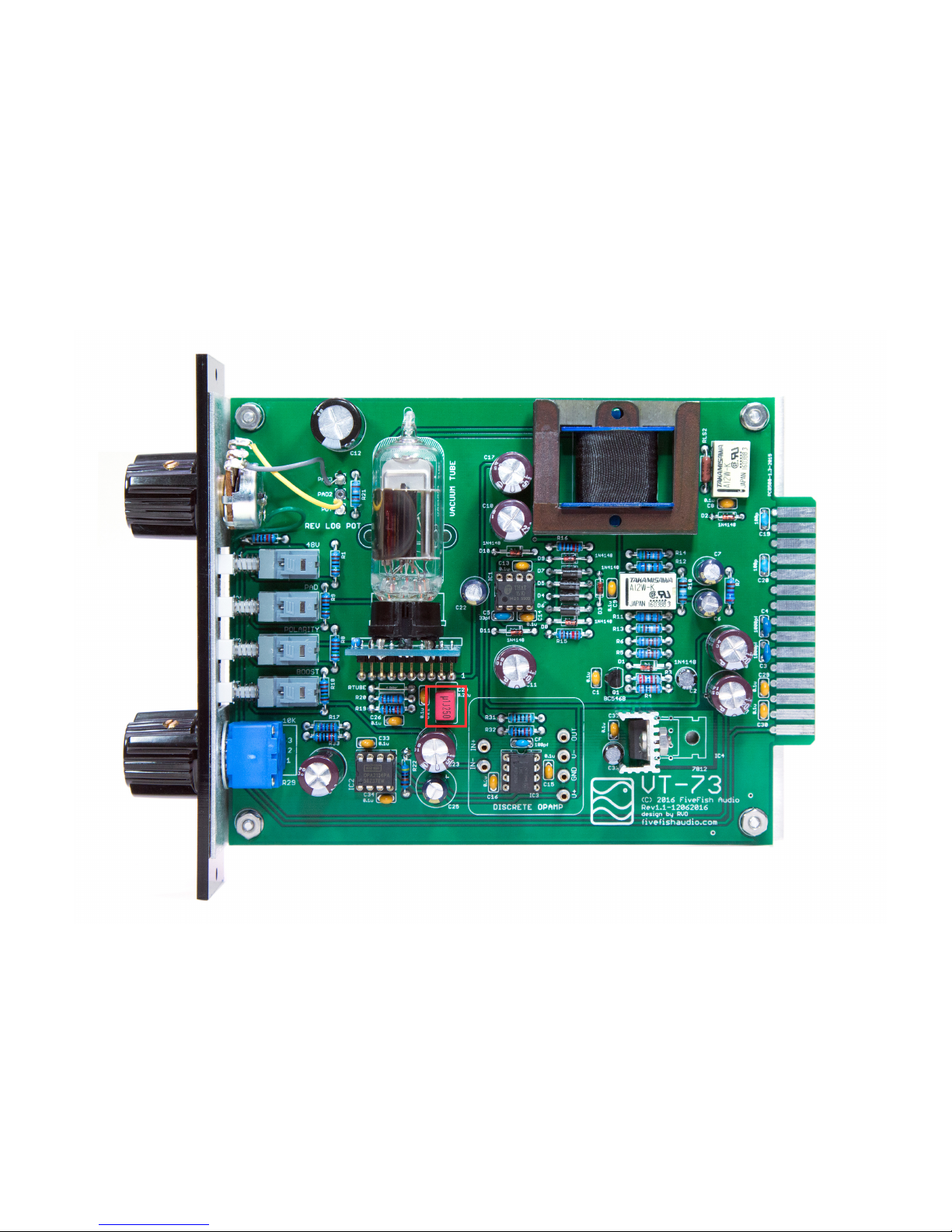
3.6 Solder the 0.1uf WIMA, C24 capacitor (Color Red).
Page 15
Copyright © 2017 FiveFish AudioVT-73 Hybrid Tube Mic Preamp Assembly Guide
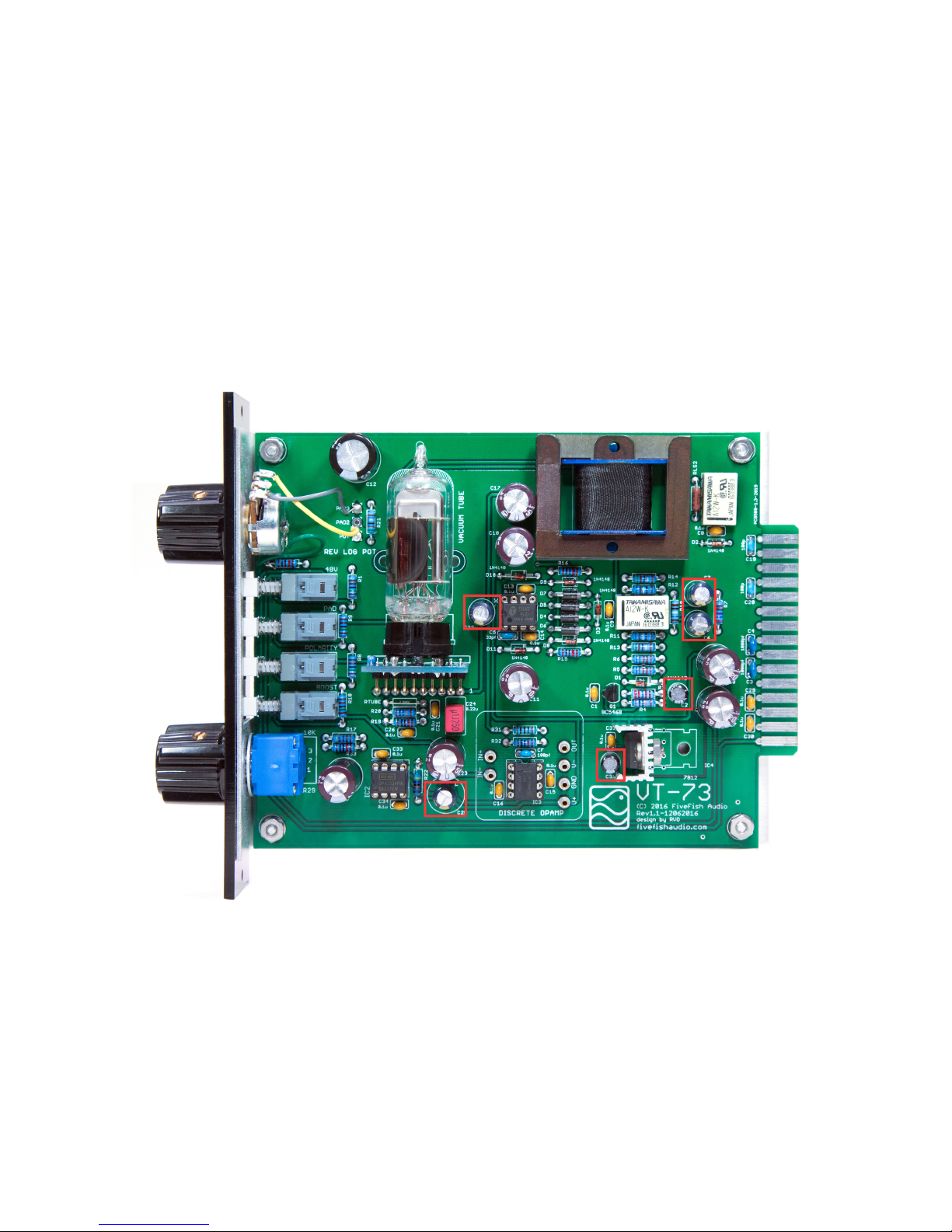
3.7 Solder all small Electrolytic Capacitors. These capacitors have polarity markings, one lead is (+) and the other lead is (-).
ERRATA: Use 47uf/50V for C25 location.
IMPORTANT: Observe the proper polarity when inserting these capacitors. Match polarity with PCB silkscreen markings. All
negative (-) leads of electrolytic capacitors are orientated facing downwards.
Page 16
Copyright © 2017 FiveFish AudioVT-73 Hybrid Tube Mic Preamp Assembly Guide
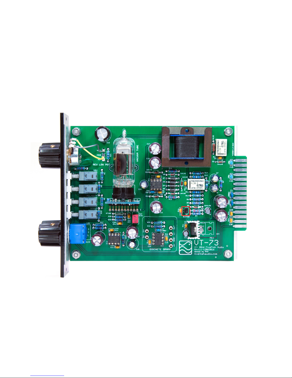
3.8 Solder Q1 Transistor.
IMPORTANT: Observe proper orientation and the direction transistor is facing. Follow the PCB silkscreen markings.
Page 17
Copyright © 2017 FiveFish AudioVT-73 Hybrid Tube Mic Preamp Assembly Guide
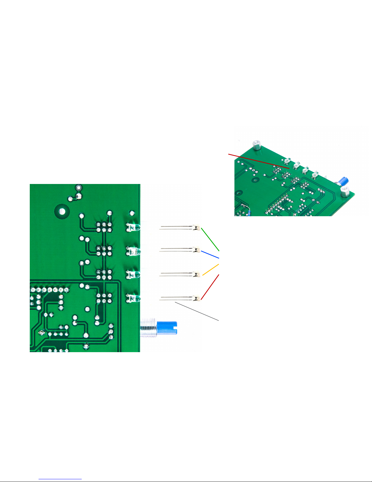
3.9 Solder all 3mm LED indicator lamps from bottom of board. These LED lamps are optional and not required.
You can arrange the LED colors any way you want. But for consistency, use the same color arrangement on all mic preamp
kits you’ll build.
A typical color arrangement may be
GREEN - for phantom power switch,
BLUE - for 20dB Pad,
YELLOW - for polarity reverse,
RED - for +12dB Boost
IMPORTANT: LONG LEG of the LED must
be oriented at the BOTTOM position as
shown.
NOTE: LEDs are installed from the bottom.
Bend LED legs as shown on photos.
Page 18
Copyright © 2017 FiveFish AudioVT-73 Hybrid Tube Mic Preamp Assembly Guide
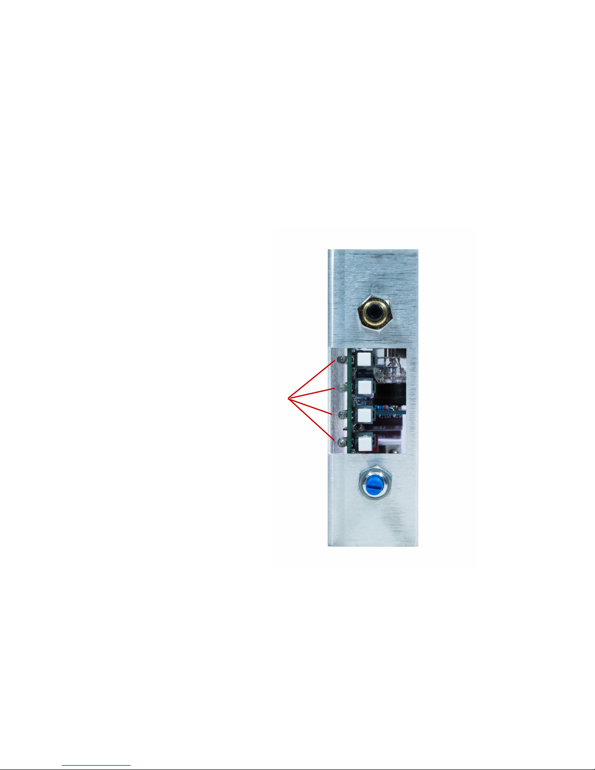
3.10 Photo showing how the (4) LEDs will show through the Aluminum cut-out panel. Note: Do NOT attach the panel yet.
NOTE: LEDs are mounted at the bottom of the PCB.
Page 19
Copyright © 2017 FiveFish AudioVT-73 Hybrid Tube Mic Preamp Assembly Guide
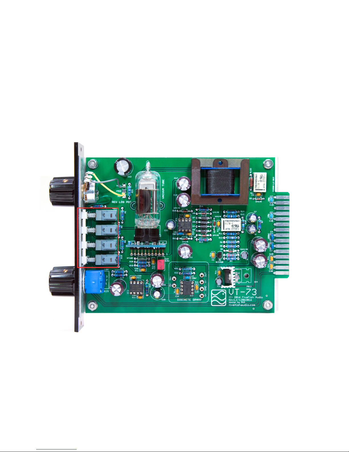
3.11 Solder the (4) Push-Button switches. Make sure they’re mounted horizontally level and not crooked or mis-aligned.
TIP: You may use masking tape to hold the switch secure in it’s place while you solder. Solder only one of the switch
terminals and review if the switch is still horizontally level. If everything looks good, solder the rest of the switch terminals.
Page 20
Copyright © 2017 FiveFish AudioVT-73 Hybrid Tube Mic Preamp Assembly Guide
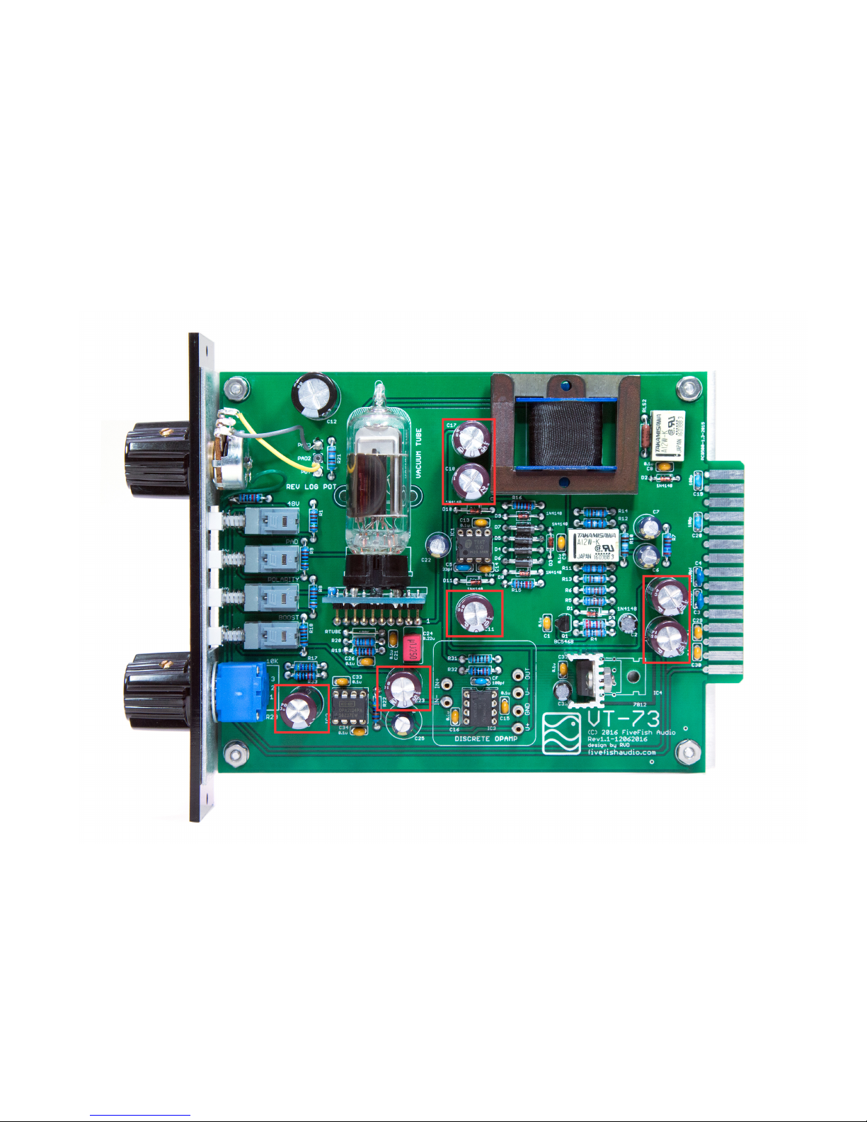
3.12 Solder all medium-sized 220uf electrolytic capacitors.
IMPORTANT: Observe proper polarity and orientation of (+) and (-) leads.
Page 21
Copyright © 2017 FiveFish AudioVT-73 Hybrid Tube Mic Preamp Assembly Guide
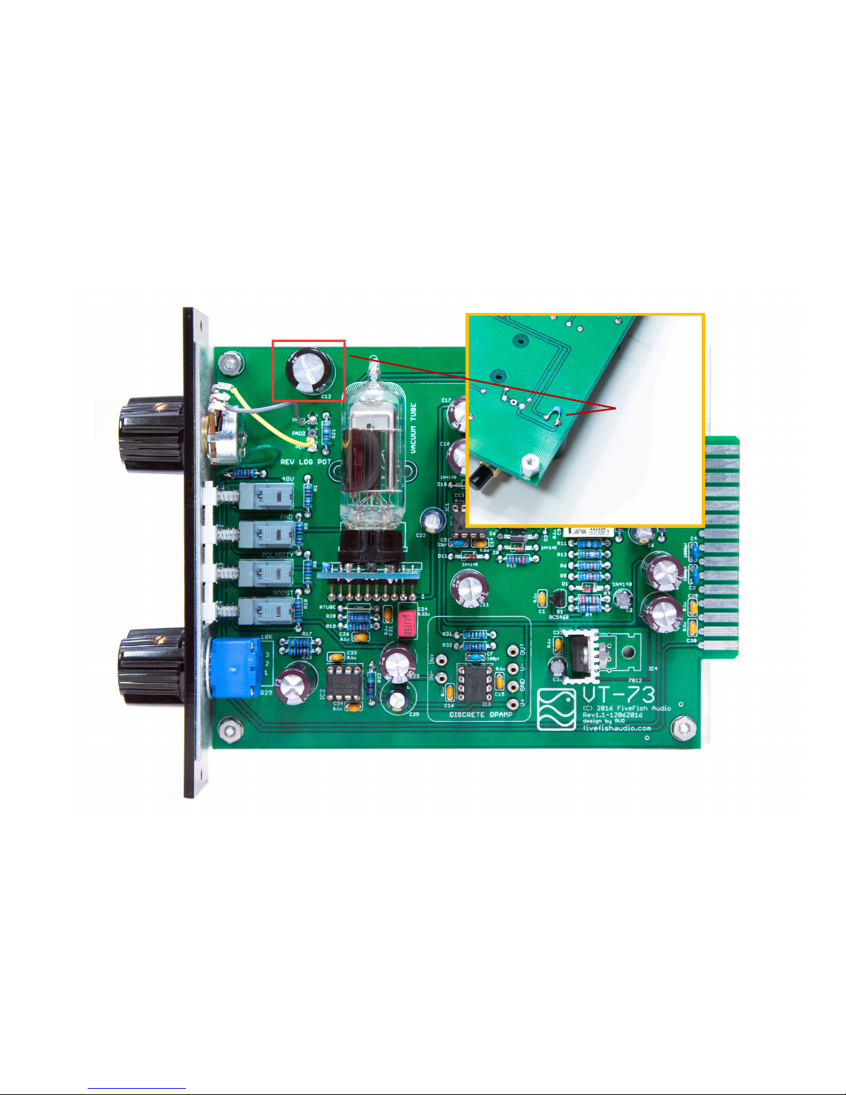
3.13 Solder the large C12, 3300uf capacitor.
NOTE: Solder 100pf capacitor in parallel to C12, from the bottom side of PCB.
Solder 100pf capacitor across
C12 from behind the PCB.
Page 22
Copyright © 2017 FiveFish AudioVT-73 Hybrid Tube Mic Preamp Assembly Guide
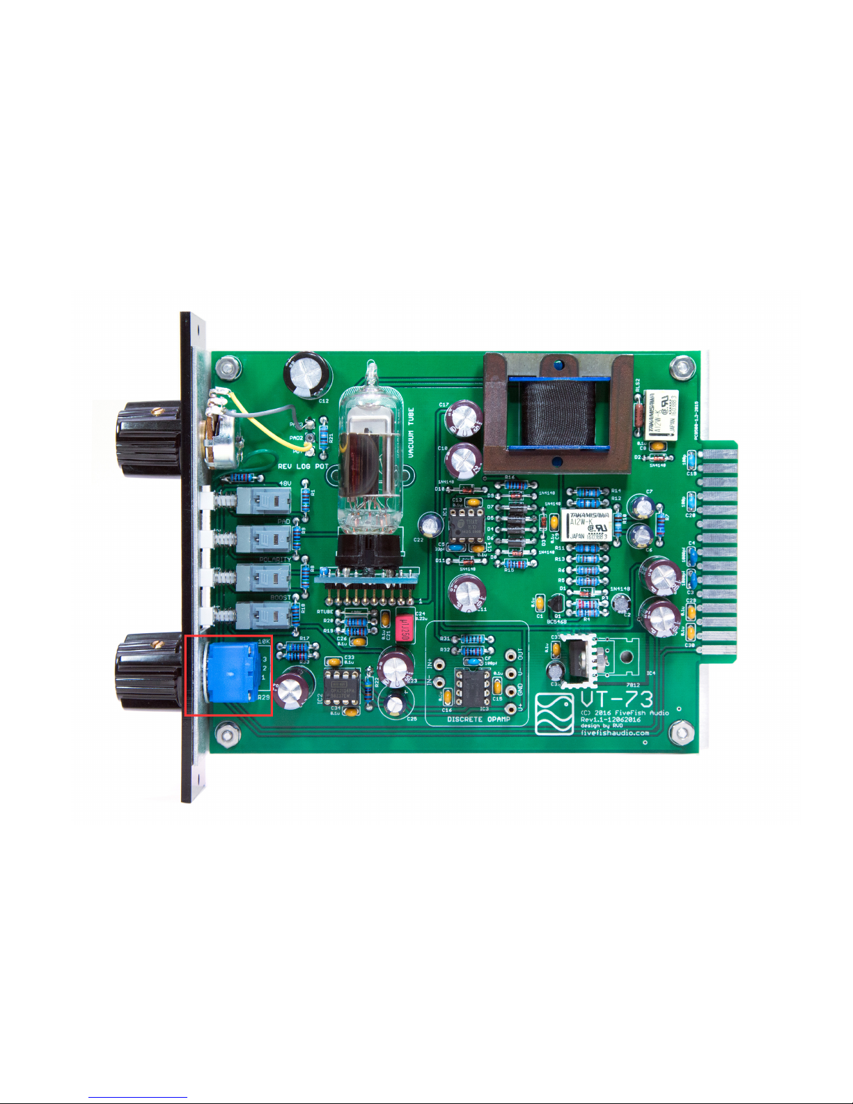
3.14 Solder the Bourns Potentiometer. Make sure to mount potentiometer level and at as possible with the PCB.
Page 23
Copyright © 2017 FiveFish AudioVT-73 Hybrid Tube Mic Preamp Assembly Guide
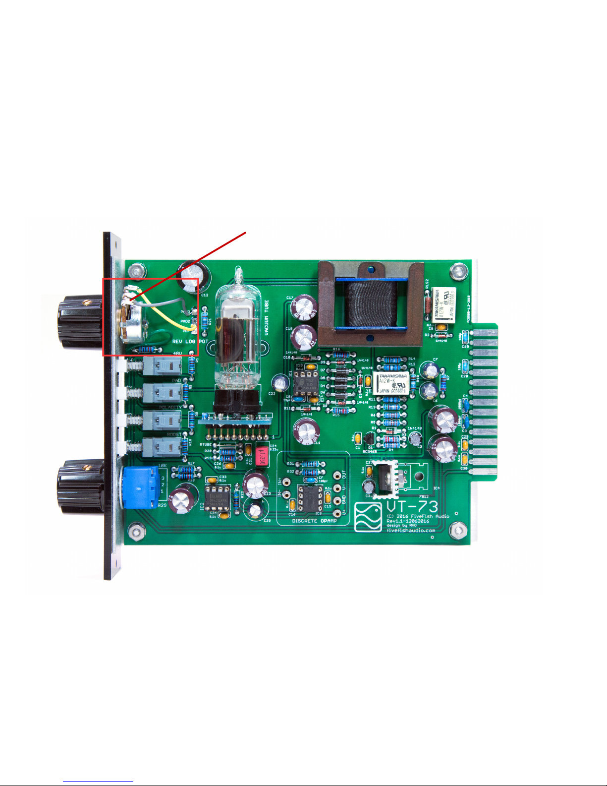
3.15 Solder the 10K Potentiometer as shown below. Take note orientation of the wires and how they go into the PCB.
IMPORTANT: Use as short as possible pieces of wire to connect potentiometer to the board to minimize RFI noise pickup.
Connect top and middle terminals of
potentiometer together.
Page 24
Copyright © 2017 FiveFish AudioVT-73 Hybrid Tube Mic Preamp Assembly Guide
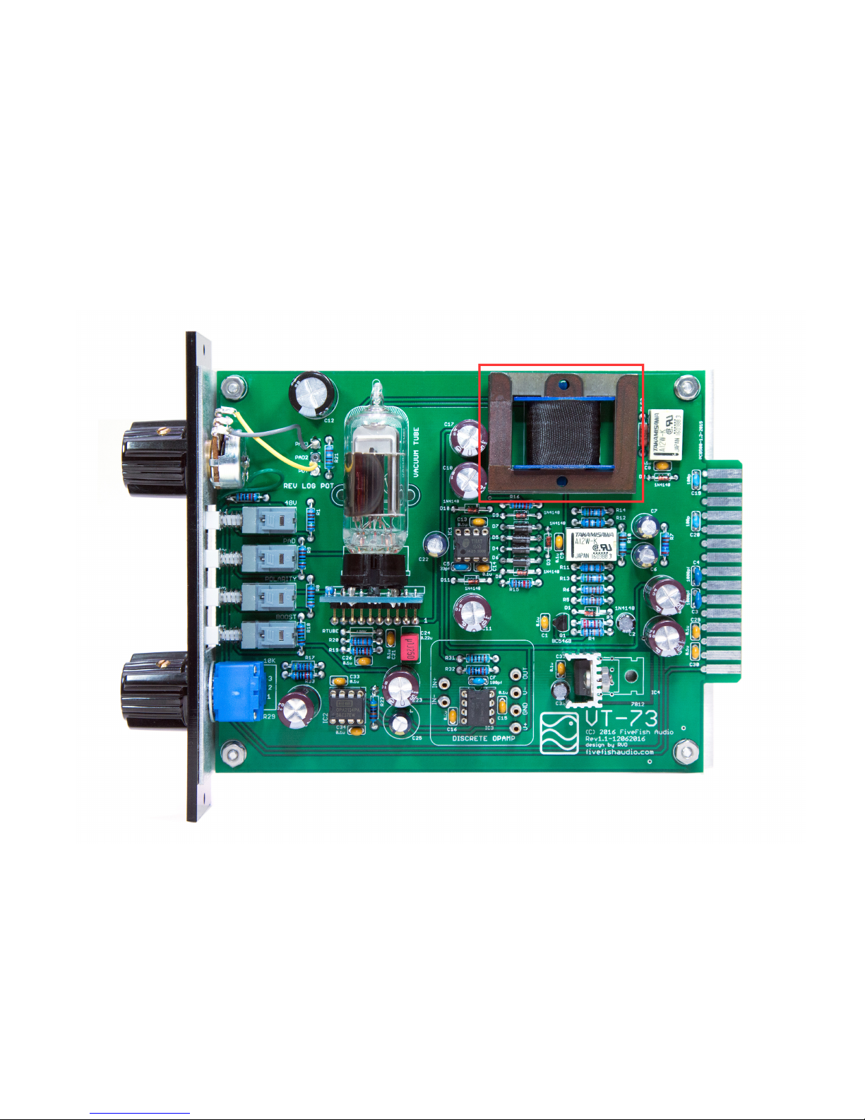
3.16 Install the Output Transformer. NOTE: Do not just duplicate the orientation of the transformer you see on this page. Instead,
rely on the keyed PCB pins of the transformer. It only goes easily/correctly in one direction. If the transformer pins don’t align
with the PCB holes, turn the transformer around and try again.
Page 25
Copyright © 2017 FiveFish AudioVT-73 Hybrid Tube Mic Preamp Assembly Guide
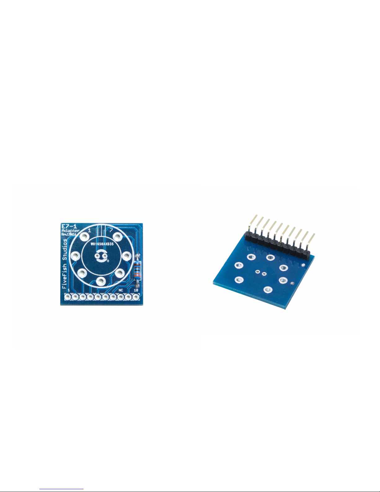
3.17 Now, let’s assemble the Vacuum Tube PCB Adapter board. Our Vacuum tube will be mounted in a tube socket for easy
future replacement. The PCB Adapter board is then soldered to the main board using right-angle headers, making the tube
orientation vertical once the 500-series preamp is inserted into the rack.
First step is to solder the current-limiting resistor for the LED.
Next, solder the Right-Angle Headers to the board as shown. Turn over the PCB, and solder the headers from the
component side of the board. Take note that the shorter leg is soldered to the PCB!
Page 26
Copyright © 2017 FiveFish AudioVT-73 Hybrid Tube Mic Preamp Assembly Guide
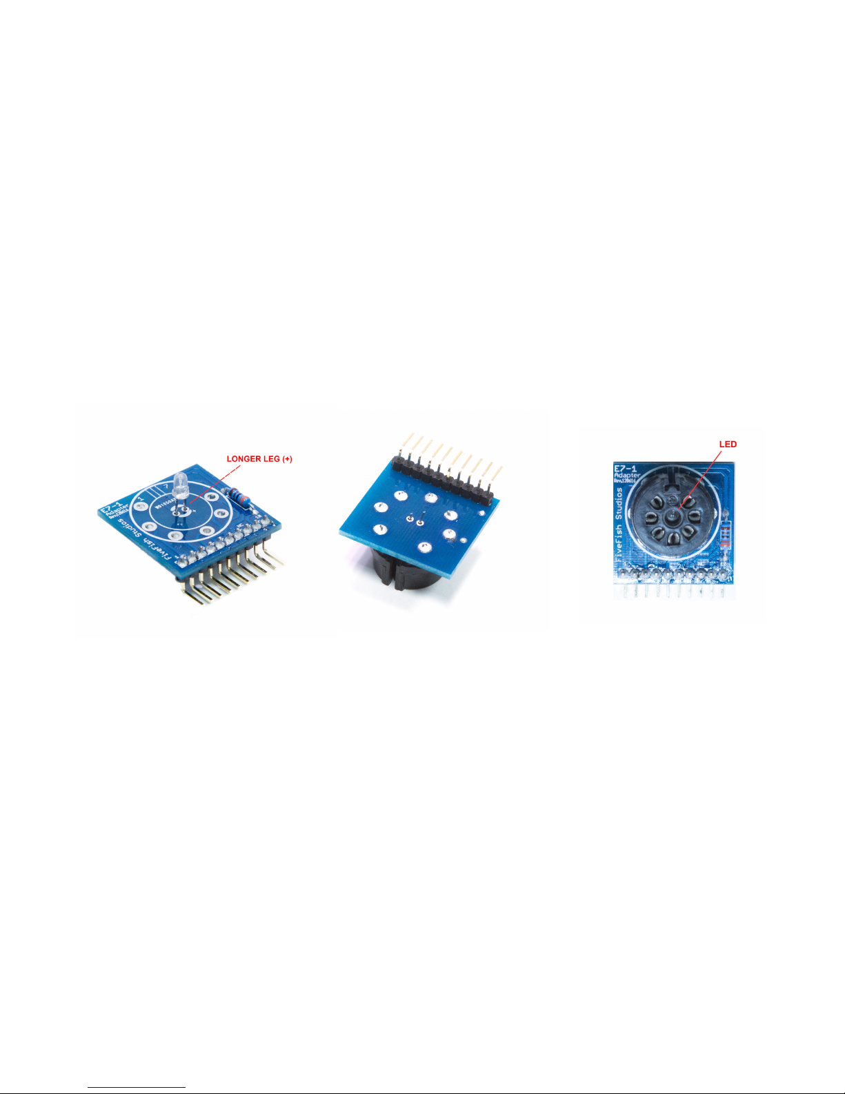
3.18 A. Insert (but DO NOT SOLDER) the Red LED into the Adapter Board.
Make sure to follow the proper orientation. The “Longer” leg of the LED goes to the hole marked with a (+) sign.
Do not solder the LED yet!
B. Insert and solder the Vacuum Tube socket. Solder all (7) pins to the board.
C. After you’ve soldered the Vacuum Tube socket, position the Red LED into the center hole of the Tube socket. Then
solder the LED leads.
Figure 3.18 A Figure 3.18 B Figure 3.18 C
Page 27
Copyright © 2017 FiveFish AudioVT-73 Hybrid Tube Mic Preamp Assembly Guide
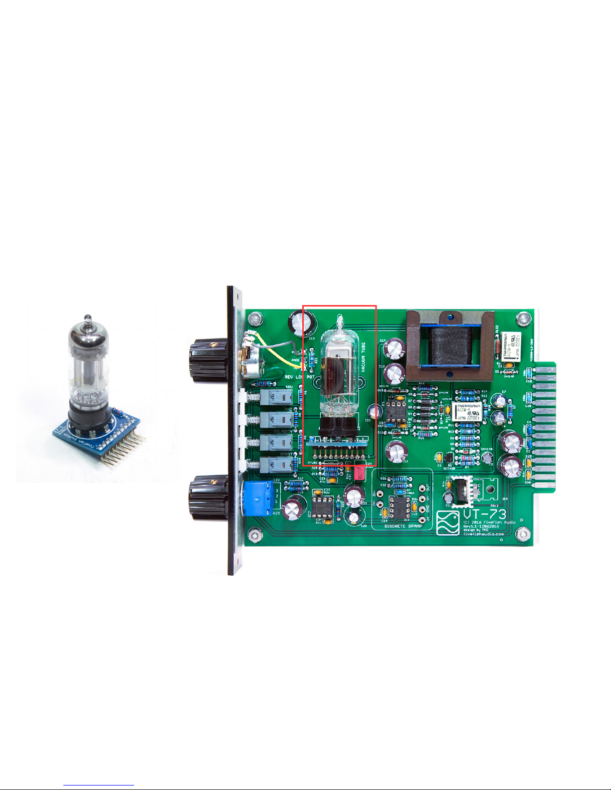
3.19 Insert Vacuum Tube into socket, rmly but carefully. For easier insertion, wiggle the tube side-by-side as you insert it.
Then mount the complete Vacuum Tube PCB Adapter assembly to the main board, and solder the right-angle headers.
NOTE: The vacuum tube can have varying degrees of microphonic vibrations that can be heard with your audio signal. To
reduce these vibrations, insert the rubber tube damper over the glass body. You may also tie and secure the tube to the PCB
using a short string or cut piece of rubber band to further reduce vibrations.
Page 28
Copyright © 2017 FiveFish AudioVT-73 Hybrid Tube Mic Preamp Assembly Guide
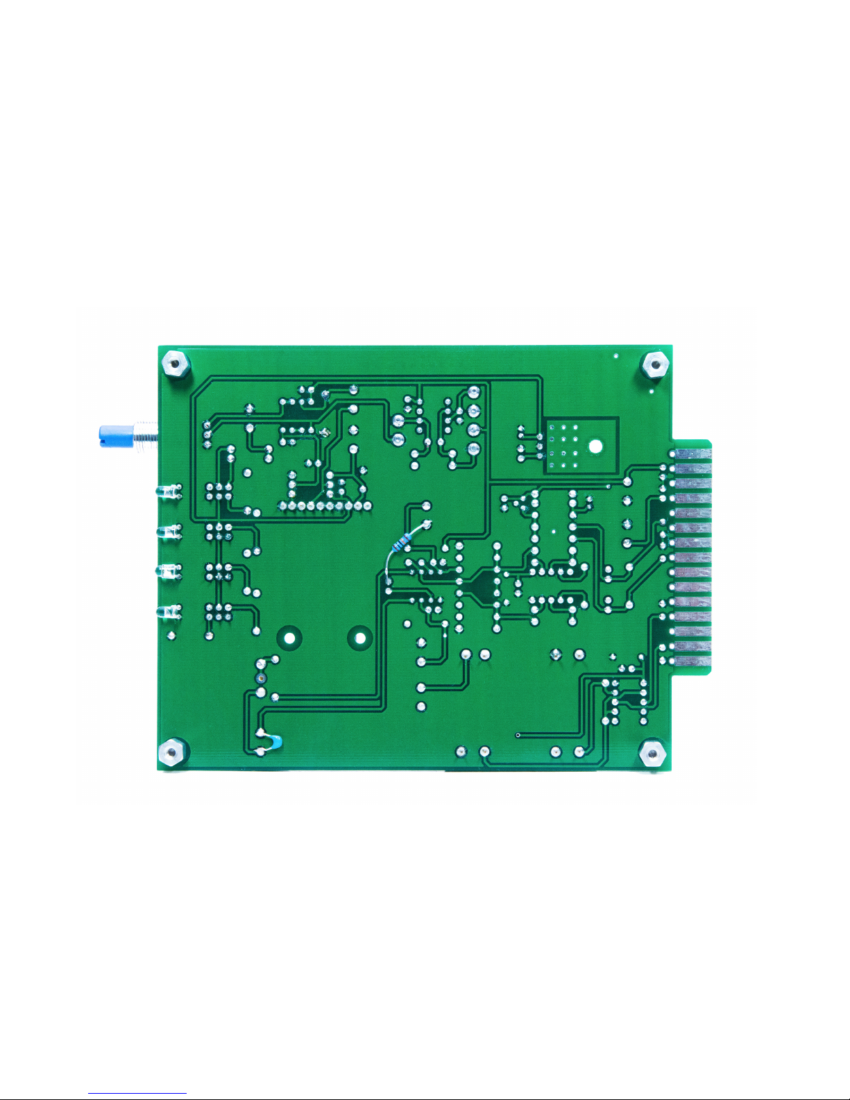
3.20 ERRATA: Solder a 100K resistor to bottom of PCB as shown in photo below. Make sure you also have a 100pf capacitor
soldered in the location below.
Page 29
Copyright © 2017 FiveFish AudioVT-73 Hybrid Tube Mic Preamp Assembly Guide
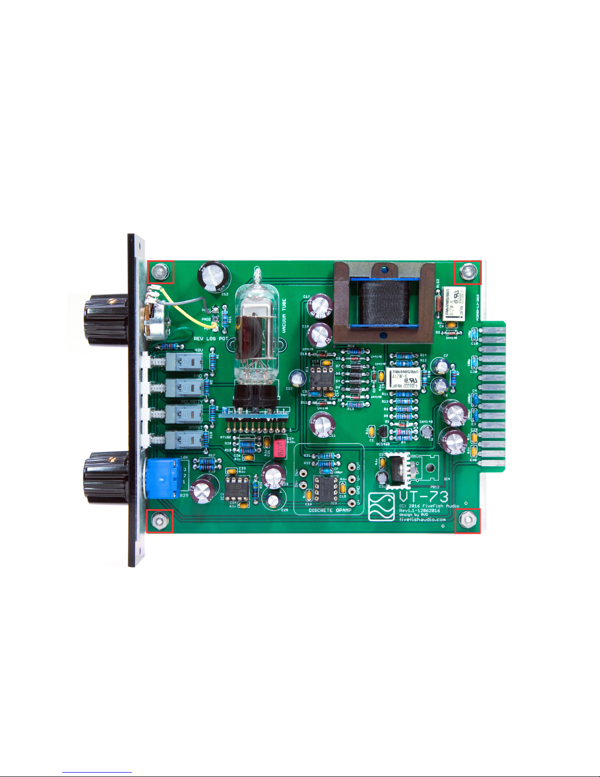
3.21 Install mounting spacers to PCB using the Aluminum Male-Female Hex Spacers and 4-40 nuts. Then mount PCB to
aluminum sled using the provided small screws.
Page 30
Copyright © 2017 FiveFish AudioVT-73 Hybrid Tube Mic Preamp Assembly Guide
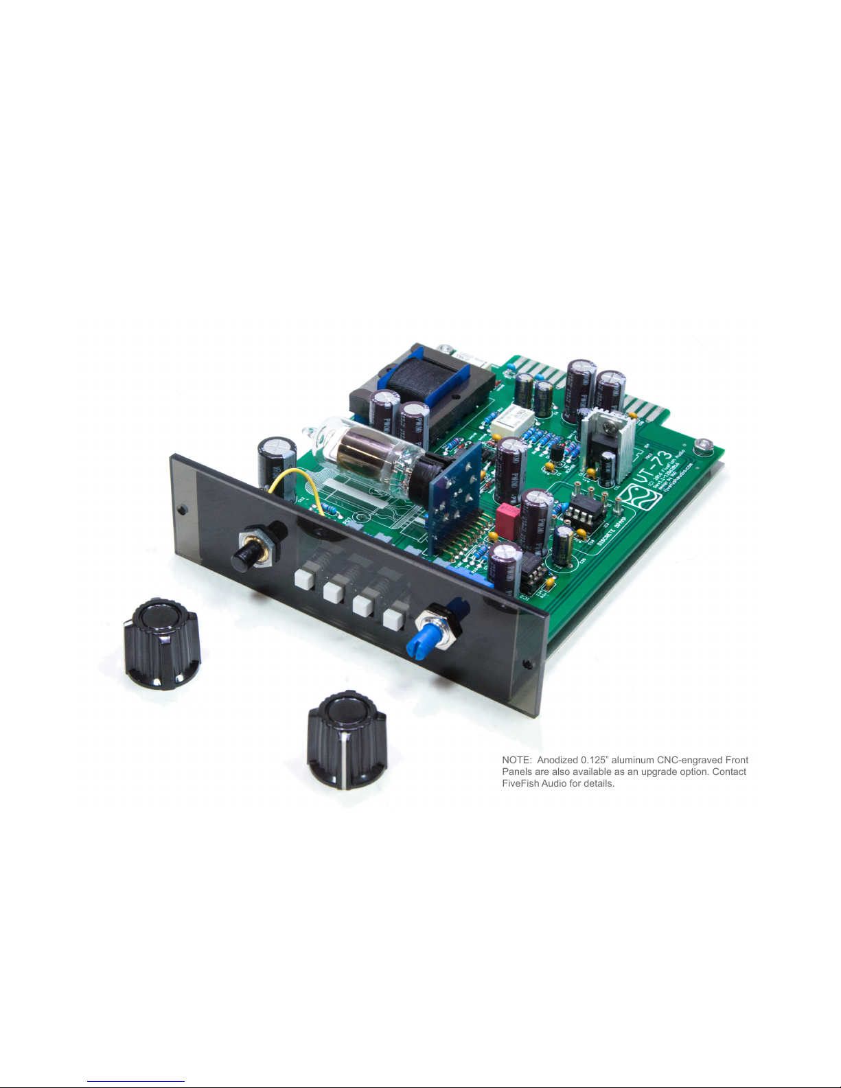
3.22 Attach the transparent acrylic front panel. Tighten nuts of potentiometers securely.
IMPORTANT: Do not overtighten nuts to avoid cracking the Acrylic Front Panel.
Then install knobs by tightening the set screw on knob.
NOTE: Anodized 0.125” aluminum CNC-engraved Front
Panels are also available as an upgrade option. Contact
FiveFish Audio for details.
Page 31
Copyright © 2017 FiveFish AudioVT-73 Hybrid Tube Mic Preamp Assembly Guide
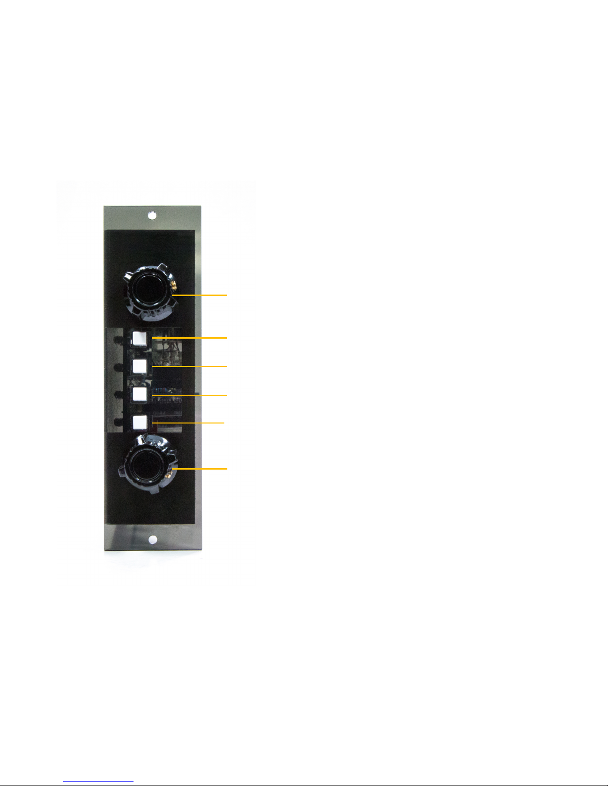
NOTE: VT-73 Mic Preamp Kit comes with a 3mm Transparent Gray Acrylic front panel.
The lighted LEDs show through very nicely through the tinted transparent front panel.
48V Phantom Power
-20dB Pad
Polarity Reverse
+12dB Boost
Output Trim
Gain Control
Page 32
Copyright © 2017 FiveFish AudioVT-73 Hybrid Tube Mic Preamp Assembly Guide
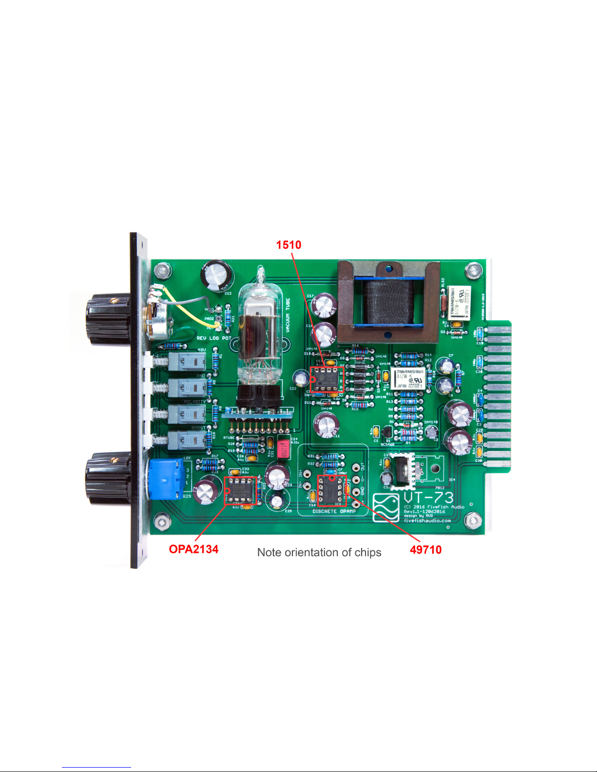
3.23 Insert the (3) IC chips into their sockets. There is a proper orientation for each chip. Take note of the half-circle cutout on the
Chip Body, and orient the IC chip as shown in the photo below.
IC1 = THAT 1510; IC2 = OPA2134; IC3 = LME49710
Page 33

Copyright © 2017 FiveFish AudioVT-73 Hybrid Tube Mic Preamp Assembly Guide
3.24 Take a coffee break!
Page 34

Copyright © 2017 FiveFish AudioVT-73 Hybrid Tube Mic Preamp Assembly Guide
4. ERRATA / MANUAL CHANGE INFORMATION
The following changes are required for PCB version 1.1
4.1 Use a wire/jumper across RTUBE location.
4.2 Use 470K for R22 location.
4.3 Solder 100K resistor at bottom of PCB as shown in Step 3.20
4.4 Use 47uf/50V for C25 location.
4.5 Solder a 100pf capacitor in parallel to C12, from the bottom side of PCB as shown in Step 3.13
4.6 Use 100K resistor for R20 location.
4.7 Use 5R1 resistor for R21/RPOT location.
Page 35

Copyright © 2017 FiveFish AudioVT-73 Hybrid Tube Mic Preamp Assembly Guide
is page intentionally le blank.
Page 36

Copyright © 2017 FiveFish AudioVT-73 Hybrid Tube Mic Preamp Assembly Guide
5. PRE-FLIGHT CHECK
Before applying power to the unit, please review your work one last time.
Go over Step 3, and in particular review the following specic items:
5.1 Perform a visual inspection. Check for any cold solder joints, or short circuit bridges.
5.2 Check if all diodes are installed in correct orientation.
5.3 Check if all polarized electrolytic capacitors are installed in correct orientation.
5.4 Check if all relays are installed in correct orientation.
5.5 Check if jumper to bypass IC4 is required (only required if using A12W-K Relays).
5.6 Check if IC1, IC2, and IC3 are inserted in their correct locations and oriented correctly.
5.7 Check if 100pf capacitor is soldered, as instructed in Step 3.13
5.8 Check if 100K resistor is soldered, as instructed in Step 3.20
Page 37
Copyright © 2017 FiveFish AudioVT-73 Hybrid Tube Mic Preamp Assembly Guide
Page 38
Copyright © 2017 FiveFish AudioVT-73 Hybrid Tube Mic Preamp Assembly Guide
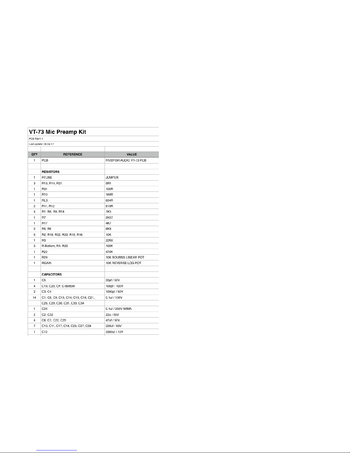
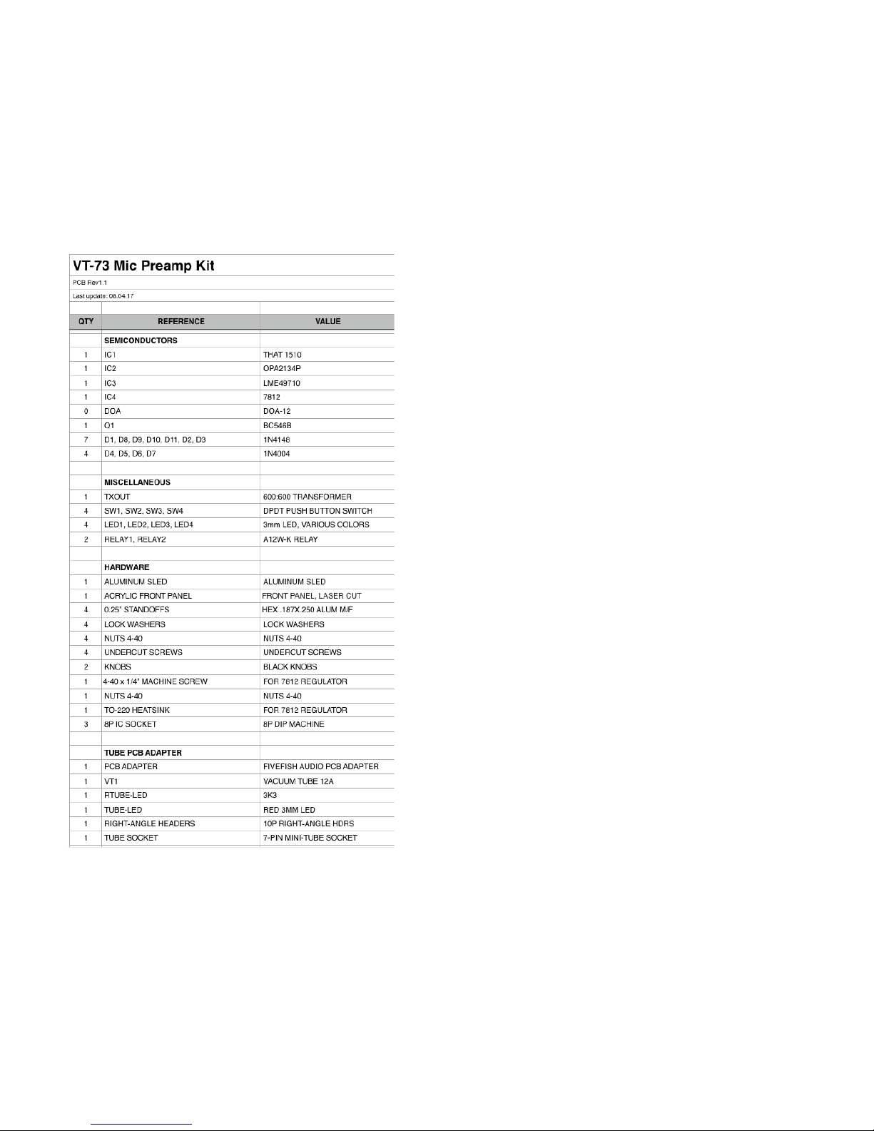
6. PARTS LIST
Page 39
Copyright © 2017 FiveFish AudioVT-73 Hybrid Tube Mic Preamp Assembly Guide
Page 40
Copyright © 2017 FiveFish AudioVT-73 Hybrid Tube Mic Preamp Assembly Guide
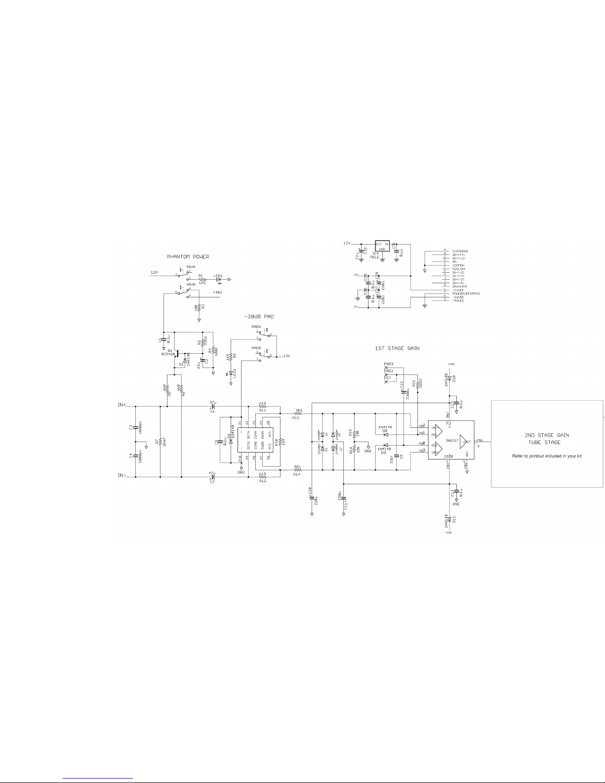
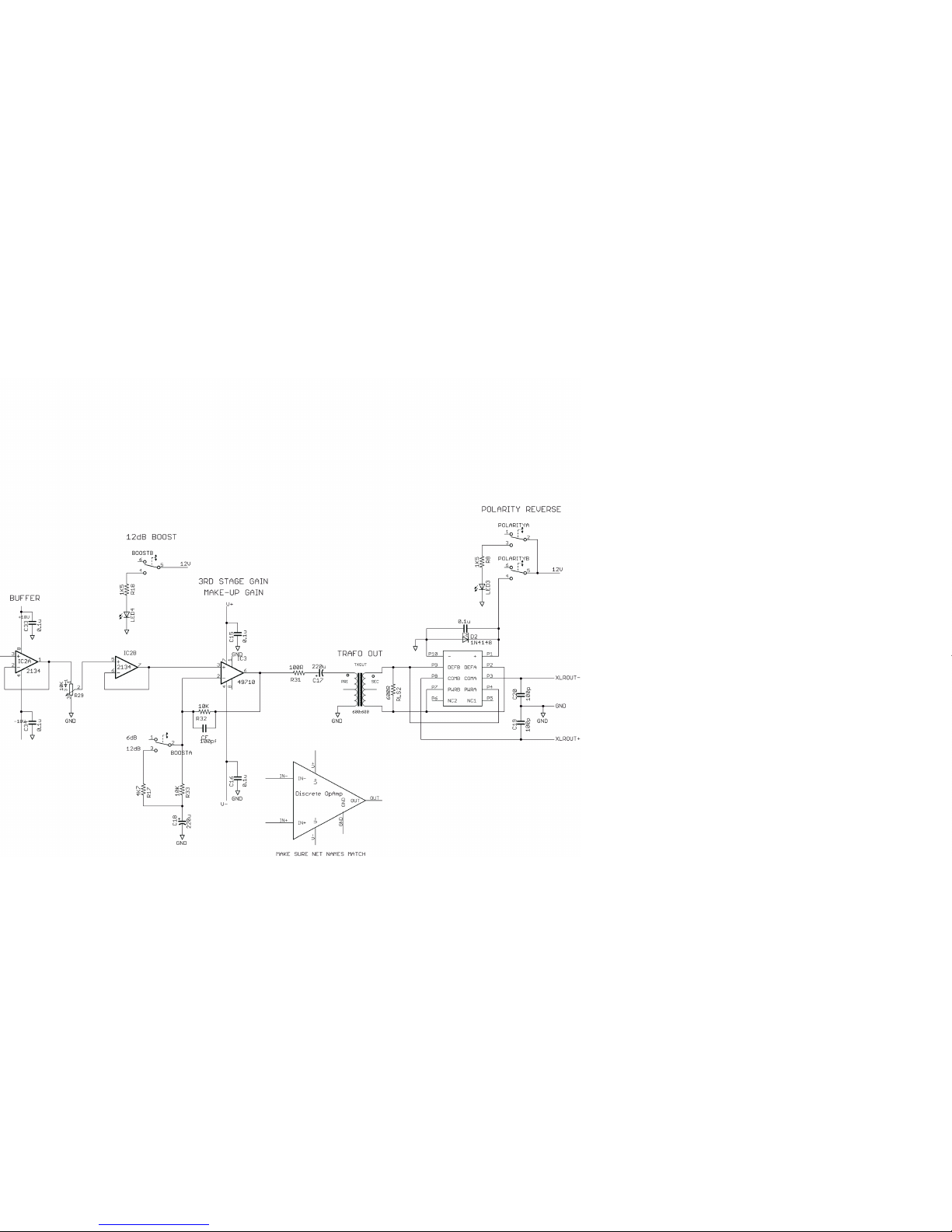
7. SCHEMATIC DIAGRAM
Page 41
Copyright © 2017 FiveFish AudioVT-73 Hybrid Tube Mic Preamp Assembly Guide
Page 42
Copyright © 2017 FiveFish AudioVT-73 Hybrid Tube Mic Preamp Assembly Guide
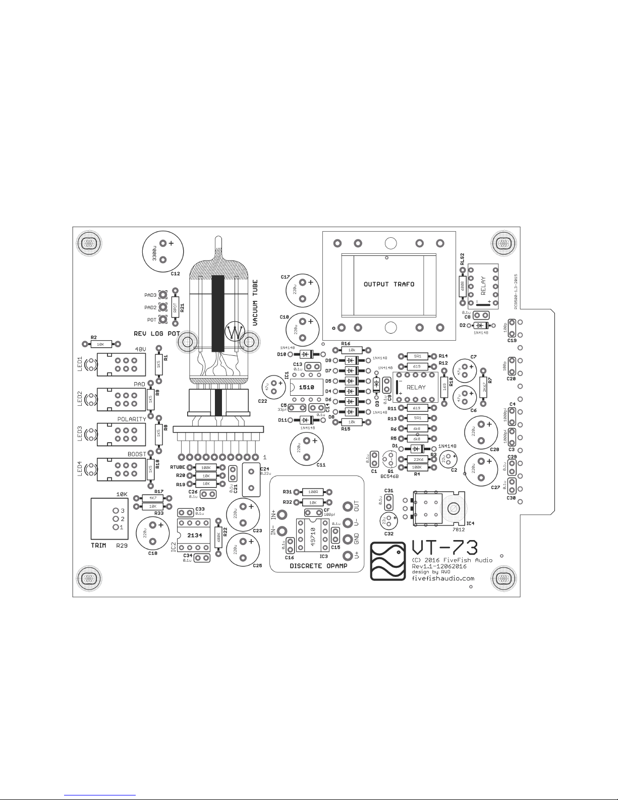
8. COMPONENT GUIDE - REV1.1 PCB
Page 43

Copyright © 2017 FiveFish AudioVT-73 Hybrid Tube Mic Preamp Assembly Guide
9. WHAT THE FAQ? (FREQUENTLY ASKED QUESTIONS)
I imagine these will be some of your questions... so I’m answering them now.
When I turn the gain knob clockwise, the sound decreases instead of increasing. At minimum gain setting, I have a very loud output signal.
It’s backwards!
Please review Step 3.15 and look closely at how the wires are connected to the potentiometer. You need to swap the location of your 2 wires if your
gain is backwards.
There is no audio output from the mic preamp.
Please review Step 4, Errata and manual changes. Also, don’t forget to solder the 100K resistor at bottom of PCB in the location shown in Step 3.20
The vacuum tube is not getting warm.
Measure voltage at ouput of Voltage Regulator. You should have approximately 12Volts DC. If you’re getting 12Volts, check solder connections
around the vacuum tube area. Also check for proper solder on the tube socket. If the vacuum tube is still not getting warm, you have have a defective
vacuum tube. Contact us for a replacement.
The bottom potentiometer (TRIM Knob) sounds scratchy when I rst turn ON the unit.
This is normal. The vacuum tube needs to warm up before all DC voltages become stable and settle down to their optimum values. Please allow 6090 seconds for the tube to sufciently warmp up before using the preamp. After this alloted time, the sratchiness on the bottom potentiometer will
disappear.
There is no sound coming out, but only during the rst few seconds when I rst turn ON the unit. After that, it operates normally.
Because this is real vacuum tube preamp. :) The vacuum tube uses a glowing heater element to emit electrons needed for it’s proper operation. A
cold tube does not have sufcient electrons emitted yet to work properly, thus you’re not able to hear any audio output. The tube needs to warm up
before all DC voltages become stable and settle down to their correct values. Please allow 60-90 seconds for the tube to sufciently warmp up before
using the preamp.
I hear “springy” sound when I bump into the unit.
These are “microphonic vibrations” caused by mechanical vibrations being picked up by the vacuum tube. To eliminate or reduce these vibrations,
use a vacuum tube damper and/or mechanically secure/tie the vacuum tube to the PCB using a short piece of string or cut piece of rubber band. The
amount of these microphonic vibrations can vary depending on the tube.
Page 44
Copyright © 2017 FiveFish AudioVT-73 Hybrid Tube Mic Preamp Assembly Guide
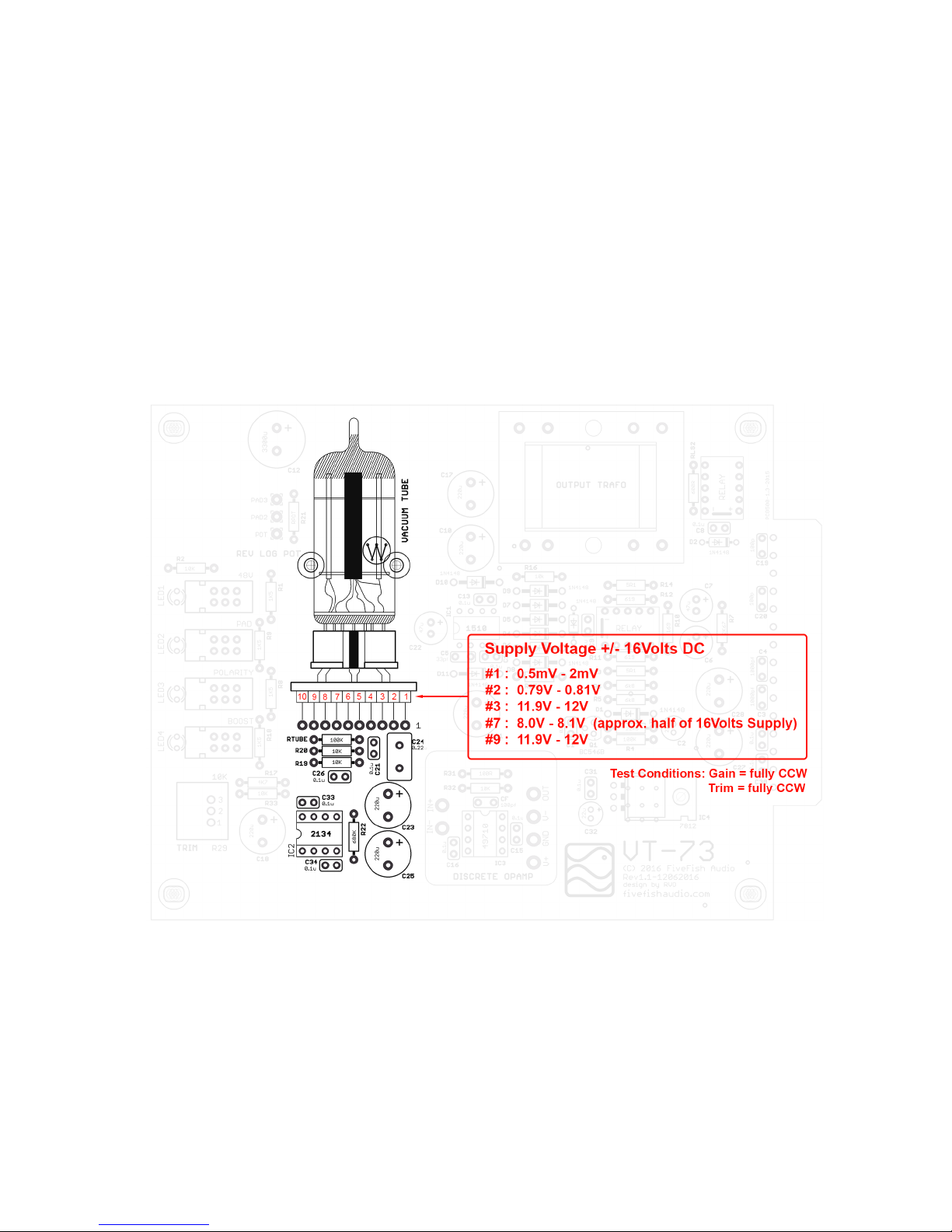
10. TROUBLESHOOTING - VOLTAGE MEASUREMENTS
If your preamp is not functioning, please review Section 4 ERRATA and Section 5 PRE-FLIGHT CHECK.
In addition, here are some approximate/typical voltage readings around the Vacuum Tube section. If your voltage
readings are several orders of magnitude wrong, please re-check for any missing parts or parts in the wrong location.
Page 45

Copyright © 2017 FiveFish AudioVT-73 Hybrid Tube Mic Preamp Assembly Guide
A Tip regarding Vacuum Tubes
This Mic Preamp Kit uses either New or (NOS) New Old Stock Vacuum Tubes and Tube Sockets.
Due to the age of these parts, the terminals may have oxidized over time. It’s recommended that you clean the Vacuum Tube
terminals using either steel wool or ne sand paper or something similar to scrape off the oxidized lm on the terminals that
may prevent making a good electrical connection.
If you’re getting incorrect voltage readings around the tube section (see previous page), AND you’ve veried all parts are
soldered in the correct location and you don’t have any other build mistakes, try re-seating the Vacuum Tube from it’s socket,
and re-inserting them again. Repeat these steps a few times. It could be the Vacuum Tube is not making a good electrical
connection with the Tube Socket terminals.
Page 46
Copyright © 2017 FiveFish AudioVT-73 Hybrid Tube Mic Preamp Assembly Guide
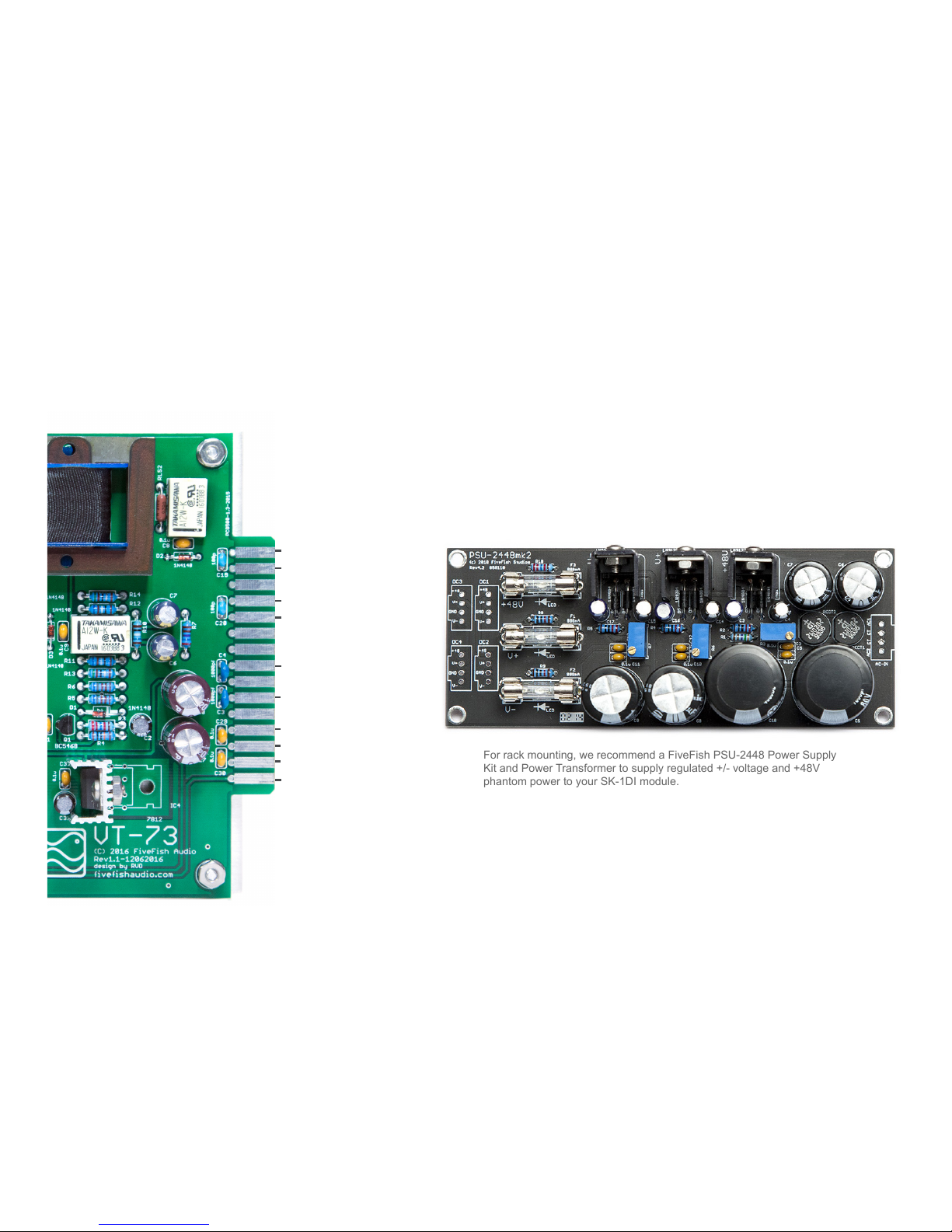
11. RACK MOUNTING THE VT-73 MIC PREAMP MODULE
For rack mounting, we recommend a FiveFish PSU-2448 Power Supply
Kit and Power Transformer to supply regulated +/- voltage and +48V
phantom power to your SK-1DI module.
You may also mount the VT-73 Mic Preamp inside a custom 1u 19” rack case. Just supply the preamp module with the necessary
+/- voltages, and connect to XLR male and female jacks. Use the wiring guide below. You can use a 15-pin EDAC connector, or
solder the connection wires directly to the holes provided on rear of the board.
+48V DC
-16V to -18V DC
GND
+16V to +18V DC
CHASSIS / GND
XLR OUT + HOT
XLR OUT - COLD
XLR IN + HOT
XLR IN - COLD
GND
Page 47
Copyright © 2017 FiveFish AudioVT-73 Hybrid Tube Mic Preamp Assembly Guide
 Loading...