

Page 1
1 / 28
FCO130 MediaPlayer FiveCo User Manual v.1.0
Full HD Media Player
Controled by I2C
With HDMI and LVDS output
FCO130 MediaPlayer FiveCo
User Manual
Version 1.0
See page 8 for
quick start
Page 2

2 / 28
FCO130 MediaPlayer FiveCo User Manual v.1.0
Version: 1.0
Last revision: December 2015
Printed in Switzerland
© Copyright 2002-2015 FiveCo Sàrl. All rights reserved.
The contents of this manual may be modified by FiveCo without any warning.
Trademarks
Linux® is a registered trademark of Linus Torvalds.
Warning
This device is not intended to be used in medical, life-support or space products.
Any failure of this device that could cause serious consequences can be prevented through the
implementation of backup systems. The user agrees that protection against consequences resulting from
device system failure is the user's responsibility. Changes or modifications to this device not explicitly
approved by FiveCo will void the user's authority to operate this device.
Page 3

3 / 28
FCO130 MediaPlayer FiveCo User Manual v.1.0
Revision history
Revision
Date
Author
Note
Hardware
Version
Bootloader
version
OS
version
App
version
1.0
08.12.2015
FR
- First revision
1.2c
Since 1.2
1.0
1.5
Page 4

4 / 28
FCO130 MediaPlayer FiveCo User Manual v.1.0
Table of Contents
1. Package and operating conditions .............................................................................................................. 5
Package contents ................................................................................................................................................. 5
Operating conditions ........................................................................................................................................ 5
2. Overview ................................................................................................................................................................. 6
Applications ............................................................................................................................................................ 6
Hardware description ....................................................................................................................................... 7
3. Quick start .............................................................................................................................................................. 8
Plug and Play .......................................................................................................................................................... 8
4. Hardware ................................................................................................................................................................ 9
Power supply ......................................................................................................................................................... 9
I2C Address ........................................................................................................................................................... 9
Screen type ......................................................................................................................................................... 10
5. Configuration file .............................................................................................................................................. 16
General .................................................................................................................................................................. 16
6. Video Type .......................................................................................................................................................... 18
Naming video ..................................................................................................................................................... 18
Video Format ..................................................................................................................................................... 18
7. I2C Register ......................................................................................................................................................... 19
List of registers ................................................................................................................................................... 19
TYPE ....................................................................................................................................................................... 20
VERSION ............................................................................................................................................................. 21
MEDIAACTION ............................................................................................................................................... 22
BRIGHTNESS ..................................................................................................................................................... 23
VIDEOOUTPUT .............................................................................................................................................. 24
AUDIOOUTPUT ............................................................................................................................................ 25
8. FMod-LEDSEQUENCER control application ................................................................................... 26
Page 5

5 / 28
FCO130 MediaPlayer FiveCo User Manual v.1.0
1. Package and operating conditions
Package contents
FCO130 MediaPlayer FiveCo
Power Supply 12V / 60W
USB Stick 4GB with this manual, video sample and configuration file
This manual
Operating conditions
Operating temperature 0 – 70 °C
Supply voltage Vcc 12 VDC
Supply current max 1.2 A (without supplying
screen backlight)
Power consumption
1
250mA at startup
160mA when playing no video
250mA when playing a video
300mA when charging new video
Input capacity (Power +,-) ?????
Max. backlight output current
o Voltage driver 4.0A
o Current driver 1.5A
Max. backlight output voltage
o Voltage driver 12V (fixed)
o Current driver 48V (9.4V min)
Minimum headphone Load 16Ω
1
The power consumption was measured with HDMI output without supplying a screen backlight
Page 6

6 / 28
FCO130 MediaPlayer FiveCo User Manual v.1.0
2. Overview
Applications
The FCO130 MediaPlayer FiveCo is a media player controlled by an I2C
bus. It can output a video signal by an LVDS (up to 2 channels 24bit color
depth) or by an HDMI.
It can read video from an usb data storage or an uSD card.
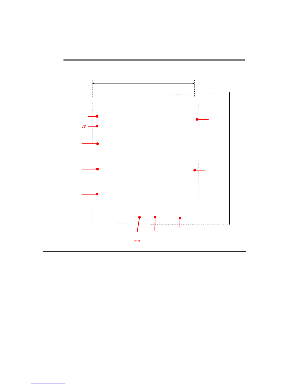
The device connections and dimensions are described on the following
pages.
Page 7
7 / 28
FCO130 MediaPlayer FiveCo User Manual v.1.0
Hardware description
Earth
Power -
Power +
(12VDC)
J1
I2C1
(second connector)
J3
I2C1
J2
USB
J9
J5
height 31.5 mm
J4
MIC
J6
LVDS2
uSD2
110 mm
137 mm
J7
LVDS1
J8
HDMI
J10
Head Phone
Figure 1 : Dimension of the media player FCO130
Page 8
8 / 28
FCO130 MediaPlayer FiveCo User Manual v.1.0
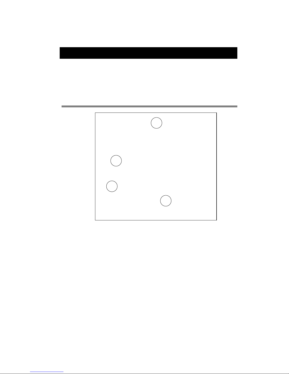
3. Quick start
This section is intended to help users quickly plug the device into their
system and play a video on an HDMI device. Detailed information about
hardware and software is provided further in this document.
Plug and Play
Figure 2 : Std connection for the FCO 130 media player
1. Connect the HDMI cable between the screen and the media player.
2. Connect the I2C cable between the mediaPlayer and the master I2C
(The default address is 0x40 or 64). If you want to use the media
player in a standalone mode you can skip this step.
3. Plus an USB storage device or a microSD with the video to play and
the configuration file.
4. Connect the DC power (12V) and wait 25 second.
5. Send I2C Command to play a video or wait a moment and the
media player start in a standalone mode.
1
2
4
3
Page 9
9 / 28
FCO130 MediaPlayer FiveCo User Manual v.1.0
4. Hardware
Power supply
A power supply with an output of 12V and minimum 20W must power the
mediaplayer. If you want to connect a screen with a LVDS connection you
must add the maximum consumption of the screen with a 1.25 factor
included the screen backlight to calculate the minimum power of the power
supply.
For example :
Screen maximum logic power : 5.5Watt
Screen backlight maximum power : 25.1 Watt
Power of power supply : P ≥ 20+(5.5+25.1)*1.25 = 58.25Watt
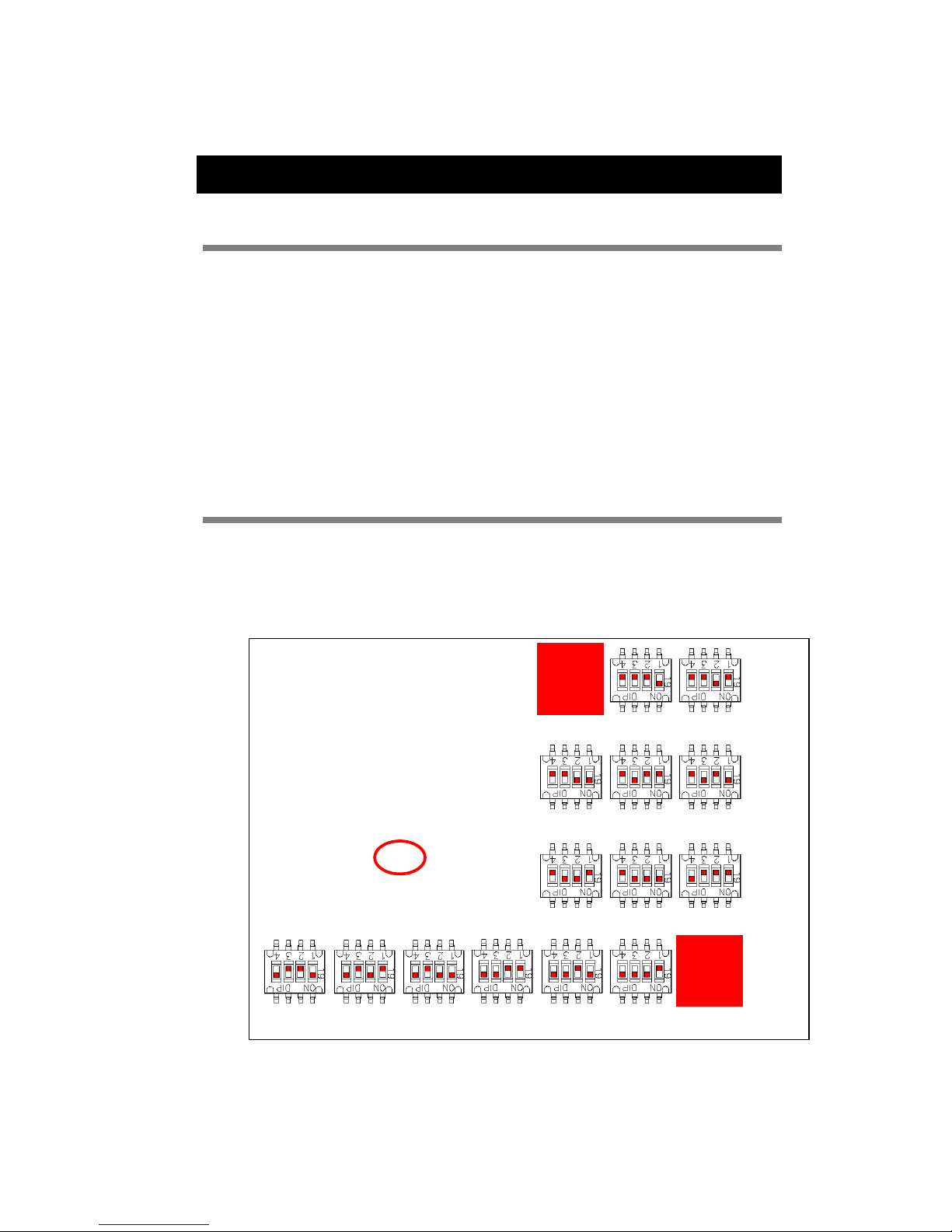
I2C Address
There are two ways to configure the I2C address of the mediaplayer. This
can be done by using the matrix switch SW7. In this case you must
comment the I2C_ADDRESS line in the configuration file. You can find
below how to configure an address with the switch matrix.
Figure 3 : Matrix switch, I2C Address
0x40
(64)
0x41
(65)
0x42
(66)
0x43
(67)
0x44
(68)
0x45
(69)
0x46
(70)
0x47
(71)
0x48
(72)
0x49
(73)
0x4A
(74)
0x4B
(75)
0x4C
(76)
0x4D
(77)
0x4E
(78)
0x4
F
Page 10
10 / 28
FCO130 MediaPlayer FiveCo User Manual v.1.0
Screen type
The media player can transmit video signal through a HDMI bus or an LVDS
bus up to two channels and 24 bit color depth. It can also power a screen
backlight and control it by sending control signals (enable, pwm) or directly
control the current to power the backlight.
To configure which video and audio output you want to use, please see the
chapter 0 “If the wanted current for the screen is not in this list, you must
choose the switch configuration with the current just higher of the wanted
current and set a PWM in configuration file to adjust the current. For
example if you must have a current of 300mA, you select the configuration
with a current of 342mA and set the PWM at 223/255 (300/342 *255 =
223).
Bootscript
LVDS Screen must have a special bootscript to configure correctly LVDS
signals.
The bootscript is a binary file place at the root of the uSD which contains
OS files.
Actually we have bootscript for following screens:
- AUO G150XG02
- AUO G190EG02V1
- AUO G173HW01
- Samsung LTN101AL03
- JXEDP02_V0.91 (lvds to edp converter)
Configuration file”.
HDMI Screen
HDMI Screen must be connected to the media player with an HDMI cable
on the connector J8. The screen must have its own power supply.
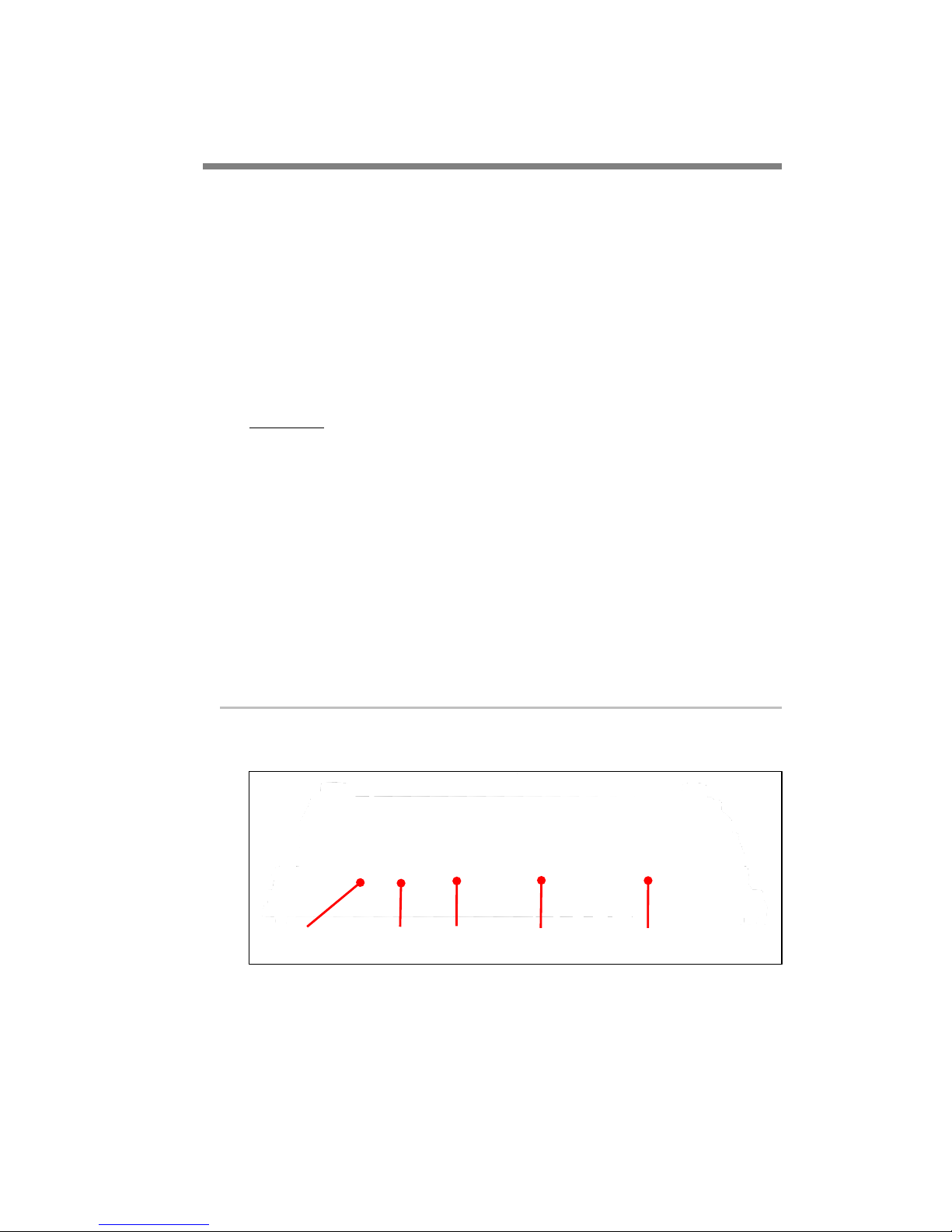
Figure 4 : Output Face of the FCO 130 media player
If you want to play a video with audio track you can transmit audio signal
through HDMI bus or through the mini jack J9 (for HeadPhone) which
transmit stereo analog signal.
If you use the mini jack connector for playing audio, be careful, you must
use a device with a minimum of 16Ohm impedance.
J9
MIC
J6
LVDS2
J7
J8
HDMI
J10
Head Phone
Page 11
11 / 28
FMod-IPECMOT 48/10 User Manual v2.5
This bus can display a video resolution up to 1920x1080px30fps.
LVDS Screen
LVDS screen must be connected to the media player with a custom cable.
There is no standard cable for LVDS, each screen must have its specific
cable.
With this media player you can connect LVDS screen which have one or
two LVDS channel and a color depth of 18bit or 24bit.
It can also power a screen backlight and control it by sending control signals
(enable, pwm) or directly control the current to power the backlight.
This bus can display a video resolution up to 1920x1080px60fps.
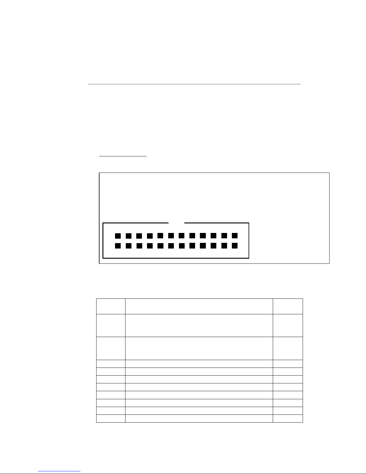
LVDS Connector
If the screen has only one channel LVDS, you must use the LVDS1
connector (J7). The pinning of this connector was described below:
Figure 5 : J7 (LVDS1) connector
Table 1 : Pin Assignment of J7 (LVDS1)
SIGNAL
NAME
DESCRIPTION
PIN(s)#
VCC
Screen electronic power supply (3.3V or 5V) can be
selected with JP1 (see below “: Screen voltage
selection”)
1, 2, 3
GND
Power Ground
4, 9, 10,
15, 16,
19, 20
TX0-
Negative LVDS differential data input
5
TX0+
Positive LVDS differential data input
6
TX1-
Negative LVDS differential data input
7
TX1+
Positive LVDS differential data input
8
TX2-
Negative LVDS differential data input
11
TX2+
Positive LVDS differential data input
12
CLK-
Negative LVDS differential clock input
13
CLK+
Positive LVDS differential clock input
13
1. VCC 2. VCC
3. VCC 4. GND
5. TX0- 6. TX0+
7. TX1- 8. TX1+
9. GND 10. GND
11. TX2- 12. TX2+
13. CLK- 14. CLK+
15. GND 16. GND
17. TX3- 18. TX3+
19. GND 20. GND
21. BL EN 22. PWM
23. 12V BL 24. 12V BL
23 21 19 17 15 13 11 9 7 5 3 1
24 22 20 18 16 14 12 10 8 6 4 2
Page 12
12 / 28
FMod-IPECMOT 48/10 User Manual v2.5
TX3-
Negative LVDS differential data input
17
TX3+
Positive LVDS differential data input
18
BL EN
Backlight enable
21
PWM
Backlight Dimming
22
12V BL
Screen backlight power supply
23, 24
The five differentials pairs must be twisted on the cable.
If the screen has only an 18bits color depth, the pair TX3 must not be
connected.
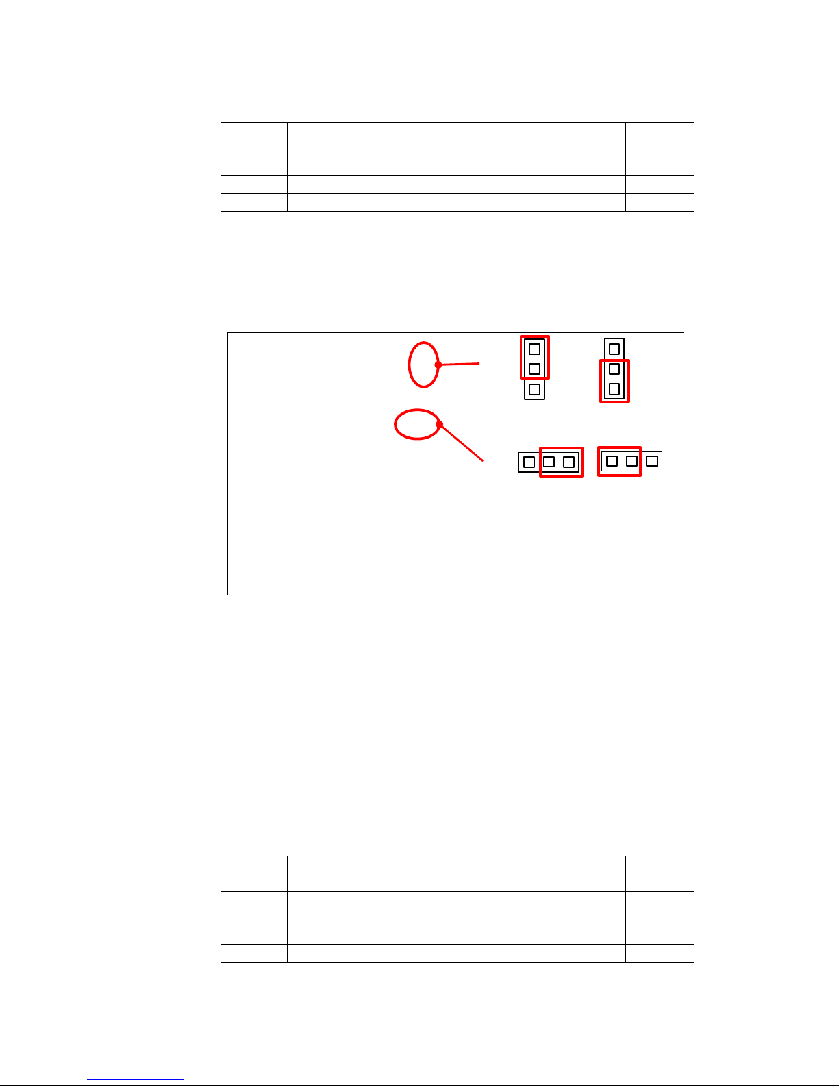
You can also select the voltage of VCC (pin 1, 2, 3) to power the screen
electronic with the Jumper JP1 shown below.
Figure 6 : Screen voltage selection
If the screen has its own electronic for backlight, you can power at 12V
with the pin 23, 24(12V) and 19, 20(GND). You can also control it with
the pin 21 (backlight enable) and 22 (Pulse With Modulation, 100% = max
luminance, 0%=no luminance).
Two channels LVDS
If the screen has two LVDS channels, you must use connectors J7 (LVDS1)
and connector J6 (LVDS2). The connector J7 has the same pin assignment
as itself when there is only one channel, but the differentials pairs are only
for odd pixels.
The pins assignments for J6 (LVDS2) are described below:
Table 2 : Pin Assignment of J6 (LVDS2)
SIGNAL
NAME
DESCRIPTION
PIN(s)#
VCC
Screen electronic power supply (3.3V or 5V) can be
selected with JP2. Be careful use the same voltage as
JP1.
1, 2, 3
GND
Power Ground
4, 9, 10,
JP1
JP2
VCC= 5V
VCC= 3.3V
VCC= 5V
VCC= 3.3V
Page 13
13 / 28
FMod-IPECMOT 48/10 User Manual v2.5
15, 16,
19, 20
TXE0-
Negative LVDS differential data input (Even data)
5
TXE0+
Positive LVDS differential data input (Even data)
6
TXE1-
Negative LVDS differential data input (Even data)
7
TXE1+
Positive LVDS differential data input (Even data)
8
TXE2-
Negative LVDS differential data input (Even data)
11
TXE2+
Positive LVDS differential data input (Even data)
12
CLKE-
Negative LVDS differential clock input (Even clock)
13
CLKE+
Positive LVDS differential clock input (Even clock)
13
TXE3-
Negative LVDS differential data input (Even data)
17
TXE3+
Positive LVDS differential data input (Even data)
18
NC
Not connected. Do not connect these pins.
21, 22
12V BL
Screen backlight power supply
23, 24
Backlight with current supply
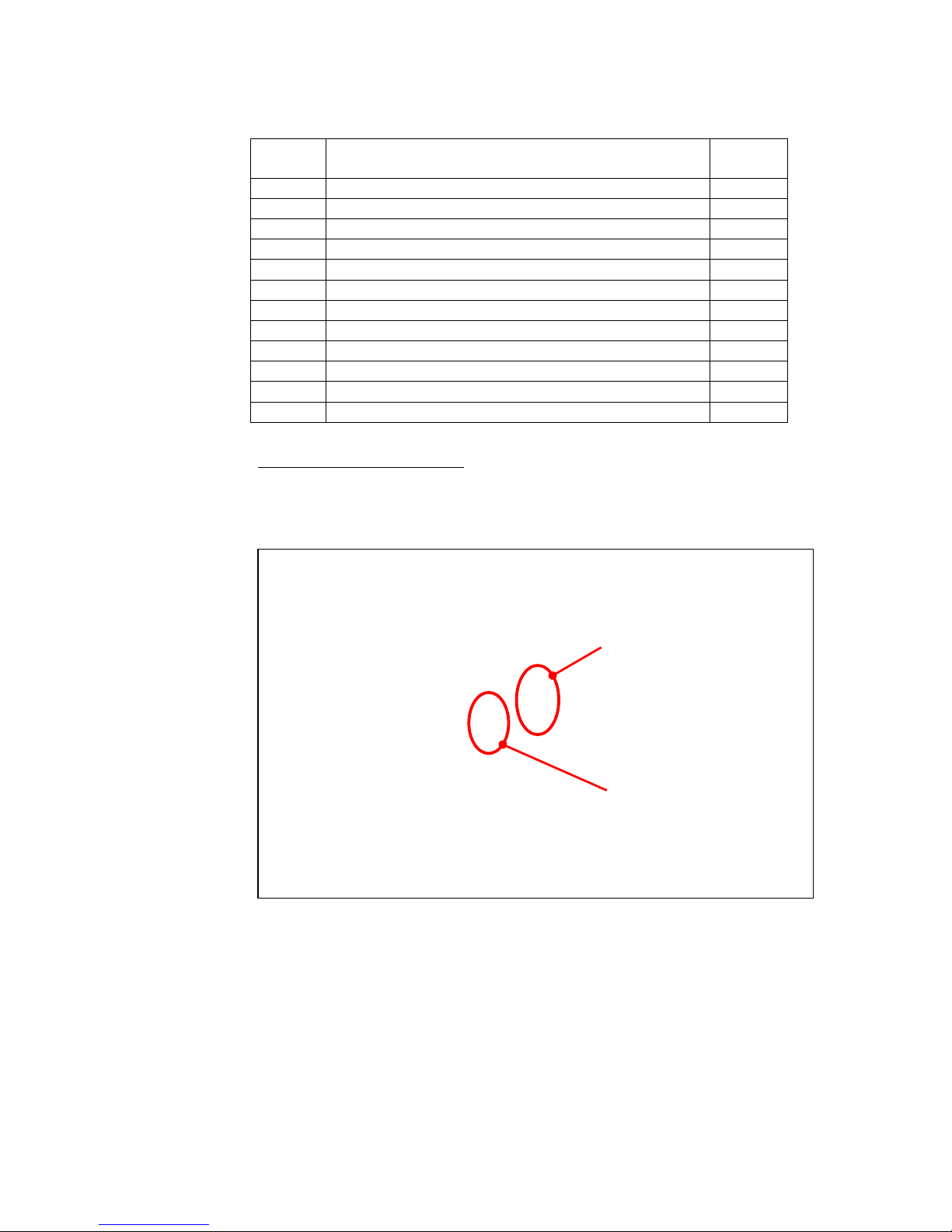
If the screen has no integrated electronic for controlling its backlight, the
media player must drive a current source for supply the backlight.
For this you must connect the backlight cable to the connector J11.
Figure 7 : Current backlight interface
The pinning of this connector J11 was described below:
J11
SW2
Current backlight
connector
Current backlight
selection switch
Page 14
14 / 28
FMod-IPECMOT 48/10 User Manual v2.5
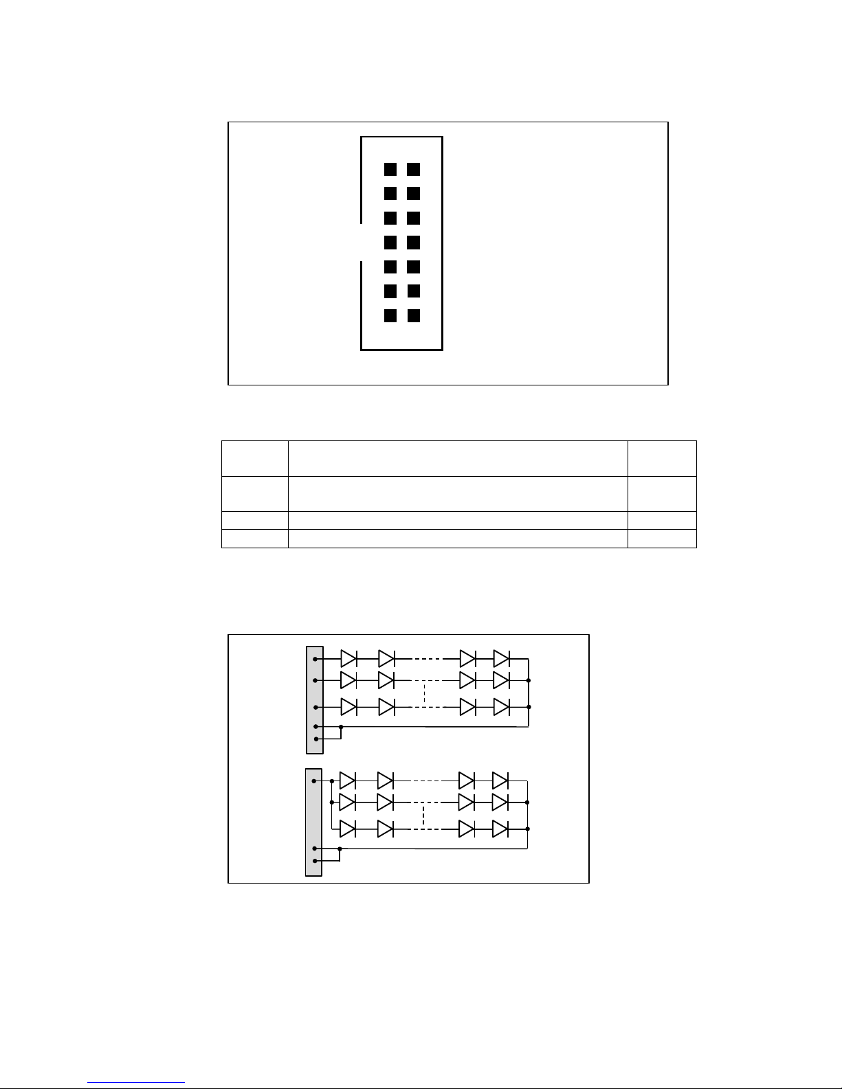
Figure 8 : J11 (Backlight current) connector
Table 3: Pin Assignment of J11 (backlight current)
SIGNAL
NAME
DESCRIPTION
PIN(s)#
Lx+
Anode for 1 Line Led (a line is several leds
connected in serial configuration). Max 80mA/line
1-10
COM+
Anode for all Backlight Unit
11, 12
COM-
Cathode for all Backlight Unit
13, 14
If the backlight connector have one pin for each line at anode side (like the
scheme bellow) please use the Lx+ pins if the current is under 80mA.
Otherwise use the COM+ pins.
Figure 9: Backlight current connection
This power supply cannot have a voltage below 12V.
Please consider this table to select the good current to supply your screen
with the SW2 (current backlight selection).
1. L1+ 2. L2+
3. L3+ 4. L4+
5. L5+ 6. L6+
7. L7+ 8. L8+
9. L9+ 10. L10+
11. COM+ 12. COM+
13. COM- 14. COM-
1
3
5
7
9
11
13
2
4
6
8
10
12
14
Use Lx+
L1+
L2+
Lx+
COM-
Use COM+
COM+
COM
Page 15
15 / 28
FMod-IPECMOT 48/10 User Manual v2.5
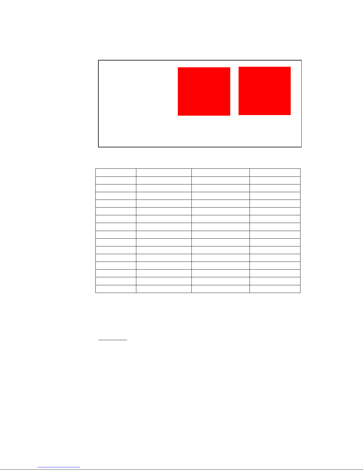
Figure 10 : Switch current backlight selection
The current is for a PWM = 100%
Switch On
Current [mA]
Voltage max [V]
Power max [W]
3
100
48
4.8
2
159
48
7.6
2+3
259
48
12.3
1
346
38
13
1+3
446
30.5
13.5
1+2
505
27.9
14
1+2+3
605
24.1
14.5
4
839
16.7
15
3+4
939
16.6
15.5
2+4
998
16.0
16
2+3+4
1’098
15.0
16.5
1+4
1’185
14.1
17
1+3+4
1’285
13.5
17.5
1+2+4
1’344
13.3
18
1+2+3+4
1’444
12.7
18.5
If the wanted current for the screen is not in this list, you must choose the
switch configuration with the current just higher of the wanted current and
set a PWM in configuration file to adjust the current. For example if you
must have a current of 300mA, you select the configuration with a current
of 342mA and set the PWM at 223/255 (300/342 *255 = 223).
Bootscript
LVDS Screen must have a special bootscript to configure correctly LVDS
signals.
The bootscript is a binary file place at the root of the uSD which contains
OS files.
Actually we have bootscript for following screens:
- AUO G150XG02
- AUO G190EG02V1
- AUO G173HW01
- Samsung LTN101AL03
- JXEDP02_V0.91 (lvds to edp converter)
All ON
All OFF
Page 16

16 / 28
FMod-IPECMOT 48/10 User Manual v2.5
5. Configuration file
General
The configuration file is a text file place at the root of the uSD or the USB
storage device which contains video to play.
This file allows some configuration for the media player.
If a line starts with ‘#’, the line was not taking into account by the media
player. To take this line into account you must remove the ‘#’.
I2C_ADDRESS
#I2C_ADDRESS 64 # i2c-address (decimal only)
# WARNING! If I2C_ADDRESS is defined, the
jumper will be ignored
If you want to set an address I2C with this configuration file, you can
remove the first ‘#’ and write the new address. The address must be
written in decimal and must be between 8 and 118.
AUTO_MODE_PAUSE_MS
AUTO_MODE_PAUSE_MS 1000 # automatic reading config (standalone)
# = 0 : disabled
# > 0 : pause between 2 videos in ms,
forward reading
# < 0 : pause between 2 videos in ms,
backward reading
This configuration is used in standalone mode, you can disable standalone
mode by setting 0 or select the time in millisecond between the end of a
video and the start of the next video.
If you want to play video 0, then video 1, then video 2 … set a positive
value. If you want to play video 10 then, then video 9, then video 8 … set a
negative value.
AUTO_MODE_INITIAL_WAIT_MS
AUTO_MODE_INITIAL_WAIT_MS 10000 # initial wait before mediaplayer starts
to auto-play
This configuration is used to define the time in millisecond before media
players starts to auto-play (standalone mode).
LVDS_BRIGHTNESS
LVDS_BRIGHTNESS 255 # Brightness [0-255], 255 = max
Page 17

17 / 28
FMod-IPECMOT 48/10 User Manual v2.5
This configuration is used to define the brightness of the screen. It works
only for LVDS screen.
0 is not backlight, and 255 is the maximum luminosity.
Be careful if you use a LVDS screen with current control on the
mediaplayer, you may not pass the maximum admissible current of the
screen.
VIDEO_DEVICE
VIDEO_DEVICE 1 # Video device selection (0 = disabled, 1 = primary, 2 = secondary)
# (1 and 2 may be HDMI or LVDS (usually 1 is HDMI))
This configuration is used to select the output to display video.
0 disable video output.
1 Select the primary output (This output give the best performance)
2 Select the secondary output
1 and 2 may be HDMI or LVDS it depend on the bootscript. If you have
the standard bootscript the primary output is HDMI.
AUDIO_DEVICE
AUDIO_DEVICE 1 # Audio device selection (0 = disabled, 1 = HDMI, 2 = jack)
This configuration is used to select the output to play audio.
0 disable audio output.
1 Select the HDMI bus to transmit audio signal.
2 Select the jack connector to transmit audio signal
Be careful do not select the HDMI output for audio if you have nothing
connected on the hdmi connector. A video with an audio track can block
the media player.
MAX_MEDIA_NB
#MAX_MEDIA_NB 1024 # Max media-file number
This line defines the maximum number of media-file.
MEDIA_DIR
#MEDIA_DIR /media/..... # My specific media repository
TODO
Page 18

18 / 28
FMod-IPECMOT 48/10 User Manual v2.5
6. Video Type
All videos to displays must be either on the micro SD on J5 or on an USB
storage device on J4 at the root of the device if a specific media repository
was not define in the configuration file.
Naming video
Each video must have a unique number, the name of the video must be
like one of the following examples:
- FILExx_nameOfTheVideo.mp4
- filexx_nameOfTheVideo.mp4
- Filexx_nameOfTheVideo.mp4
‘xx’ must be a number between 0 and 1023, some zeros can be added
before the number (like 002 or 02 or 023). This number matches to the
number of the video, if you want to play this video, send this number with
the I2C command.
Video Format
Bla bla
Size and speed
The video cannot have a memory size bigger than TODO MB. The
resolution cannot be bigger than Full HD (1920x1080p) and the speed of
the video must not be higher of 30 fps for Full HD and 60 fps for HD
ready (1280x720p).
Container
MP4 or AVI TODO.
Video Codec
TODO.
Audio Codec
TODO.
Page 19

19 / 28
FMod-IPECMOT 48/10 User Manual v2.5
7. I2C Register
List of registers
Address Byte Name
General Information
0x00 4 TYPE
0x01 4 VERSION
Command
0x20 4 MEDIAACTION
General configuration
0x40 1 BRIGHTNESS
0x41 1 VIDEOOUTPUT
0x42 1 AUDIOOUTPUT
KP, KI, KD depend mainly on the type of motor, voltage and encoder
resolution. The more the encoder has pulses per revolution, the smaller
the KP, KI, KD values will be.
The main INPUT (PWM/Speed/Position) is software-limited with
configurable INPUTMIN and INPUTMAX values.
Page 20
20 / 28
FMod-IPECMOT 48/10 User Manual v2.5
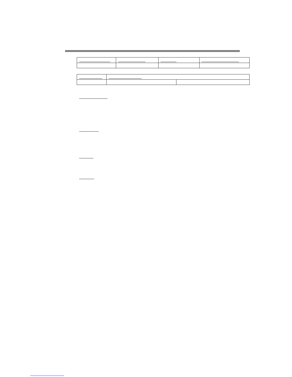
TYPE
Register Address
Register Name
Function
Read/Write Control
0x00
TYPE
Product ID
Read Only
Register Size
Register structure
4 Bytes
Unsigned Int 16 bits (HH-HL) TYPE
Unsigned Int 16 bits (LH-LL) MODEL
Description :
Product identifier composed of a Type and Model number.
It defines which kind of peripheral it is.
Normally different TYPE modules are not software compatible.
Example:
Device with TYPE = 0x002E0001 means Type = 2E (2E = FCO130
MediaPlayer), Model = 1.
Limits:
None
Active:
Each time the processor running after the boot (~25 seconds)
Page 21
21 / 28
FMod-IPECMOT 48/10 User Manual v2.5
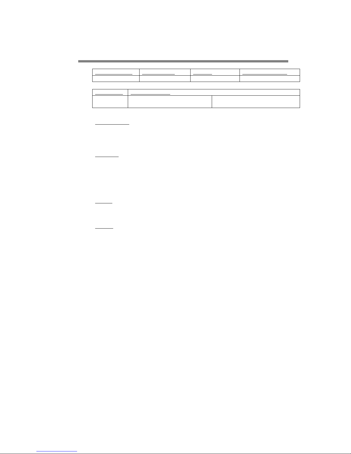
VERSION
Register Address
Register Name
Function
Read/Write Control
0x01
VERSION
Hw/Sw version
Read Only
Register Size
Register structure
4 Bytes
2x Unsigned Int 8 bits (HH-HL)
Hardware Major and minor version
2x Unsigned Int 8 bits (LH-LL)
Software Major and minor version
Description :
Hardware version and Software version, with version and revision number.
Normally same version with different revision is backward compatible.
Example:
Device with VERSION = 0x01020304 means Hardware version = 1.2,
Software version = 3.4. This software version is compatible with all earlier
revision of the same version (ver 3.0 to 3.3) but has new functionalities
(which are deactivated by default) or code optimizations.
Limits:
None
Active:
Each time the processor running after the boot (~25 seconds)
Page 22
22 / 28
FMod-IPECMOT 48/10 User Manual v2.5
MEDIAACTION
Register Address
Register Name
Function
Read/Write Control
0x20
MEDIAACTION
Action on media
Write Only
Register Size
Register structure
4 Bytes
Unsigned Int 8 bits (HH)
Action type
3x Unsigned Int 8 bits (HL-LH-LL) Action
Data
Description :
Command to do an action on the media.
Action type
Description
Action Data
1
Start new video
The number of the video
2
Pause current video
None
3
Resume current video
None
4
Stop current video
None
5
Seek current video
Time in ms
6
Load video in Pause
The number of the video
7
Configure Auto Mode
Action Data = 0 => Disabled Auto-mode
Action Data >0 => Time between video,
load next video
Action Data < 0 => Time between video,
load previous video
8
Start next video
None
9
Load next video in Pause
None
10
Start previous video
None
11
Load previous video in Pause
None
Example:
MEDIAACTION = 0x01E65405 (action type = 0x05, action data =
0x01E654 = 124500) means goes in current video at time 124.5 seconds.
MEDIAACTION = 0x00000806 (action type = 0x06, action data =
0x000008) means load video 8 and put it in Pause.
MEDIAACTION = 0xFFD8F007 (action type = 0x07, action data =
0xFFD8F0 = -10000) means configure Auto Mode with a pause of 10
seconds between videos and load previous video.
Limits:
None
Active:
Each time the processor running after the boot (~25 seconds).
Some actions (2, 3, 4, 5) works only when a video is loaded.
Page 23
23 / 28
FMod-IPECMOT 48/10 User Manual v2.5
BRIGHTNESS
Register Address
Register Name
Function
Read/Write Control
0x40
BRIGHTNESS
Sets backlight brightness
R/W
Register Size
Register structure
1 Byte
Unsigned Int 8
Description:
Sets the screen brightness.
Minimum 0 (black screen), maximum 255 (maximum luminosity).
Example:
Device with BRIGHTNESS = 0xFF means screen with full brightness.
Limits:
Works only with screen connected with an LVDS bus. Be careful some
screen with backlight current control on media player must not exceed
current max and brightness value must be lower than a specific value
lower than 255 (see Backlight with current supply on page 13) .
Active:
Each time the processor running after the boot (~25 seconds)
Page 24
24 / 28
FMod-IPECMOT 48/10 User Manual v2.5
VIDEOOUTPUT
Register Address
Register Name
Function
Read/Write Control
0x41
VIDEOOUTPUT
Sets the video output
R/W
Register Size
Register structure
1 Byte
Unsigned Int 8
Description:
Sets the video output.
0 : No video
1 : Primary video output
2 : Secondary video output
Example:
Device with VIDEOOUTPUT = 0x01 means video output on primary
output.
Limits:
HDMI and LVDS can be either primary or secondary, it depends on the
bootscript file. If the bootscript is the standard one, the HDMI is the
primary output.
Active:
Each time the processor running after the boot (~25 seconds)
Page 25
25 / 28
FMod-IPECMOT 48/10 User Manual v2.5
AUDIOOUTPUT
Register Address
Register Name
Function
Read/Write Control
0x42
AUDIOOUTPUT
Sets the audio output
R/W
Register Size
Register structure
1 Byte
Unsigned Int 8
Description:
Sets the audio output.
0 : No audio
1 : Audio output on HDMI
2 : Audio output on jack (analog output)
Example:
Device with AUDIOOUTPUT = 0x01 means audio output on HDMI bus.
Limits:
None.
Active:
Each time the processor running after the boot (~25 seconds)
Page 26
26 / 28
FMod-IPECMOT 48/10 User Manual v2.5
8. FMod-LEDSEQUENCER control application
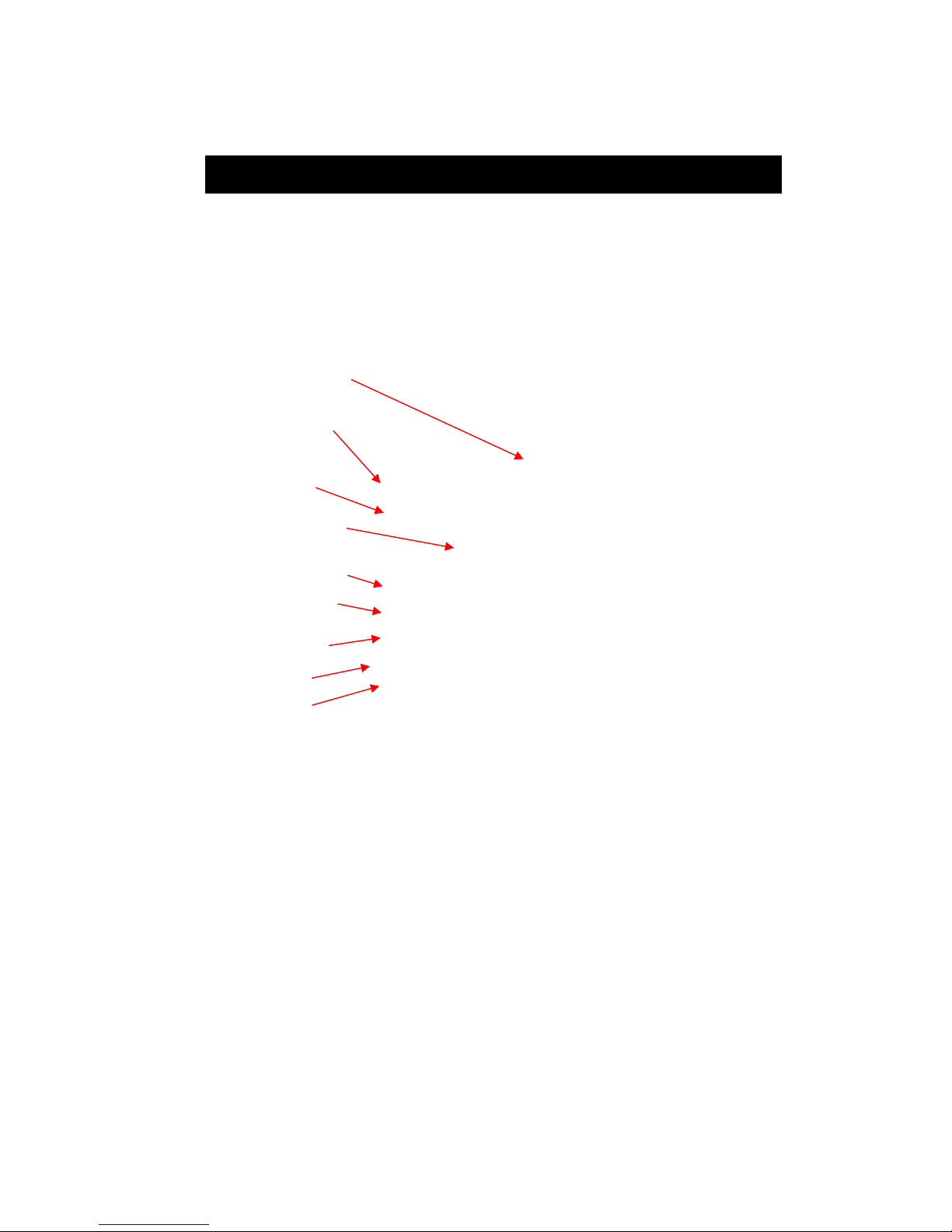
The JAVA application for the FMod-LEDSEQUENCER includes since
version 2.4 the Media Player FiveCo type.
This type has some command to play, stop pause a video.
It has also command to go at a specific time in a video.
It can also adjust brightness and select audio and video output.
Remarks :
If the pause of function « Autoplay » is negativ, the videos will be played in
reverse order.
If the case « Load only » is checked, functions « Play next file », « Play
previous file », « Play file at index » just load video and put it in « Pause »
state. You must send command « Play » to play it. This reduces the time
I2C address of the Mediaplayer
Play videos in order
and goes to the next
after the specified time
Stop, play and pause
the loaded video.
Load and play
the previous, next video.
Load and play the specified video
Go to the specified time in ms
of the loaded video.
Sets the screen brightness
in %
Sets the video output
Sets the audio output
Figure 21 : Java application, Media player
Page 27

27 / 28
FMod-IPECMOT 48/10 User Manual v2.5
and the variations of time between sending « Play » command and when
the video starts really.
« Seek » command goes to the nearest « Key Frame » of the video of the
specified time.
Page 28

28 / 28
FMod-IPECMOT 48/10 User Manual v2.5
Contact address:
FiveCo - Innovative Engineering
En Budron H11
CH-1052 Le Mont-sur-Lausanne
Switzerland
Tel: +41 21 632 60 10
Fax: +41 21 632 60 11
 Loading...