


KIDS EQUIPMENT X5/XT5/XE5/XB5/XST5
User Manual KENA:01

TABLE OF CONTENTS
Safety Instructions............................................................
Leveling ............................................................................
X5....................................................................................
XT5..................................................................................
XE5/XB5/XST5.................................................................
Stretching and Flexibility...................................................
Maintenance......................................................................
Warranty ..........................................................................
1-2
3
4-7
8-23
24-27
28-29
30-31
32

SAFETY INSTRUCTIONS
When using an electrical product, basic precautions should always be
followed, including the followning:
Read all instructions before using this exercise product. The use of this
product in any way not described in this manual is not recommended
and may cause serious or fatal injury or void your warranty.
WARNING!
To reduce the risk of burns, fire, electrical shock or injury to persons:
Use this exercise product for its intended use as described in
this Manual . Do not use attachments not recommended by
the manufacturer.
Do not insert any object, hands or feet into any openings,
or expose hands, arms or feet to the drive mechanism or
other potentially moving part of the product.
Do not remove the covers. Service should be performed only
by an authorized FITNEX retailer.
Never operate the product if it has a damaged cord or plug,
if it is not working properly, if it has been damaged, or
immersed in water. Have equipment examined by an
authorized Fitnex service provide.
Keep the cord away from heated surfaces.
Do not use outdoors.
To disconnect, turn the switch to the OFF position, then
remove plug form outlet.
Never place the power cord under carpeting or place any
object on top of the power cord, which may pinch and
damage it.
Unplug your Treadmill before moving it.
When the FITNEX equipment is in use, children under the
age of 7 and pets sould be kept at least 10 feet away.
1
DO NOT use this product while barefoot or wearing only socks.
This equipment can be used by children aged from 8 years and
above and persons with reduced physical, sensory or mental
capabilities if they have been given supervision or instruction
concerning use of the equipment in a safe way and understand
the hazards involved.
Cleaning and user maintenance shall not be made by children.
Inspect the exercise product for worn or loose components
prior to use. Tighten/replace any loose or worn components
prior to using.
Prior to operation of exercise product, please remove all
jewelries, such as rings, ear rings, and necklaces..., etc.
CAUTION
If you experience chest pains, nausea, dizziness or shortness of breath,
stop exercising immediately and consult your physician before continuing.
Do not wear clothing that might catch on any part of the Fitnex product.
Read this User Manual before operating the product.
PROPER USE
DO NOT use this product unless proper attire is worn. Rubber-soled
training, running, or tennis shoes must be worn to provide proper
traction and protection while using this product.
DO NOT use cleats, spikes or any other non-athletic style shoes.
DO NOT use this product while barefoot or wearing only socks.
DO NOT wear loose or dangling clothing while using this exericse product.
Max. user weight for X5 is 250 pounds.
Max. user weight for XT5 is 220 pounds.
Max. user weight for XE5 is 250 pounds.
Max. user weight for XB5 is 220 pounds.
Max. user weight for XST5 is 400 pounds.
Stay hydrated. Drink water throughout your workout as needed.
2
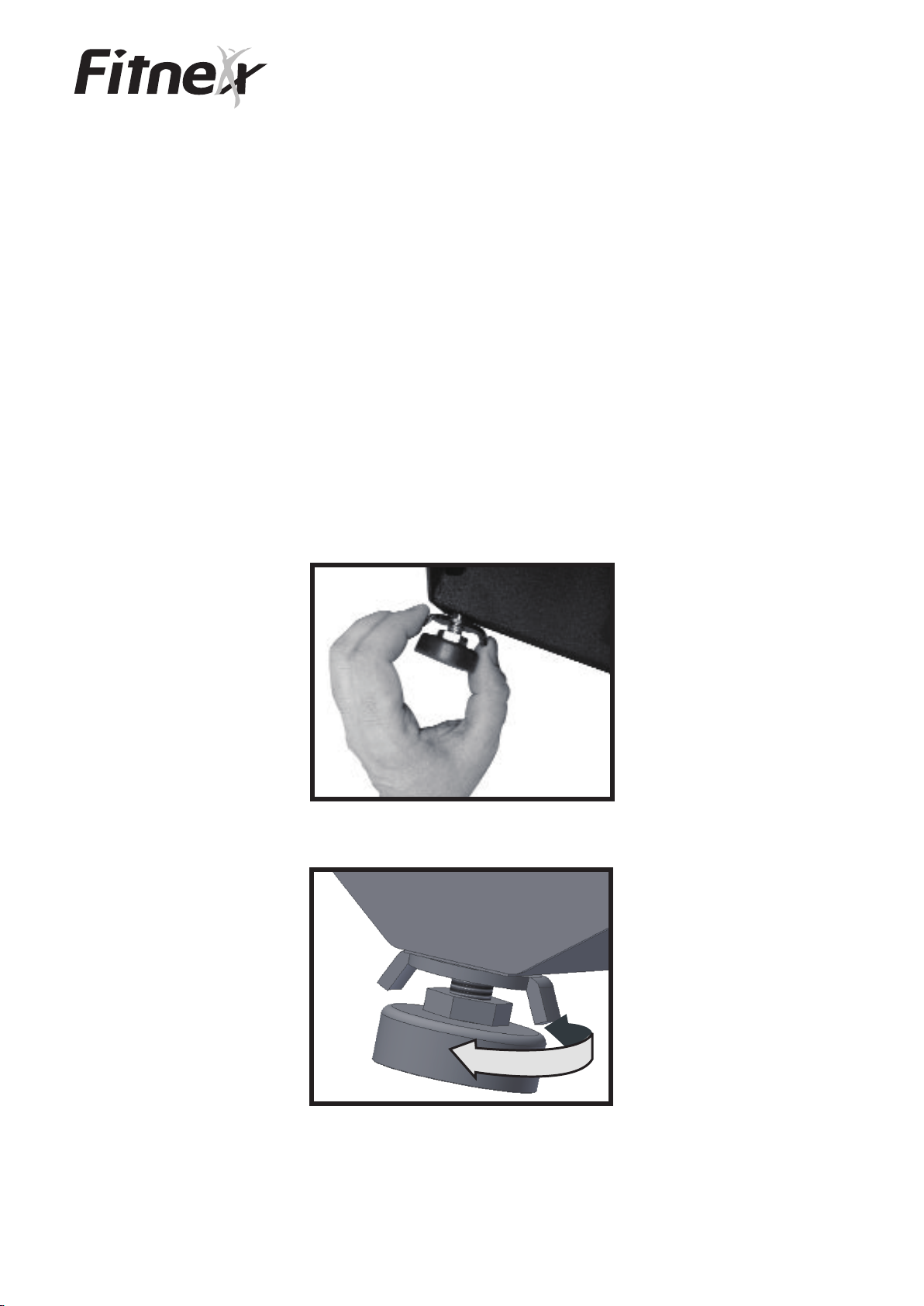
LEVELING
Please ensure to set up and operate this exericse product on a level
surface. After finding a location that is suitable for the equipment,
the legs must be adjusted to provide stable support. Located on the
side of each leg is a thumb-wheel that will allow you to lower or
raise the leg until it is properly seated on the floor.
For XT5, please DO NOT adjust legs while the treadmill is on.
Turn the power switch to the OFF position before adjustment.
Unlock the washer by hand.
Adjust the leg to fit the ground.
3
X5
SAFETY GUIDELINE
·Warm up 5-10 minutes before exercise, and cool-down 5~10 minutes
after using the bike in order to avoid any injury.
·User should take a break between each exercise cycle.
·The training requires a professional assistance. Inappropriate length of
training time and position may cause injury.
·Turn the Push Brake System knob to increase resistance after pedaling, so
the pedals will not rotate freely and potentially injure someone.
·Never turn the pedal crank arms by hands.
·Focus on form, posture and making smooth transitions between movements.
·Never remove your feet from the pedals while still in motion.
·Safety operation space:
50cm fore and back of the bike
30cm left and right side of the bike
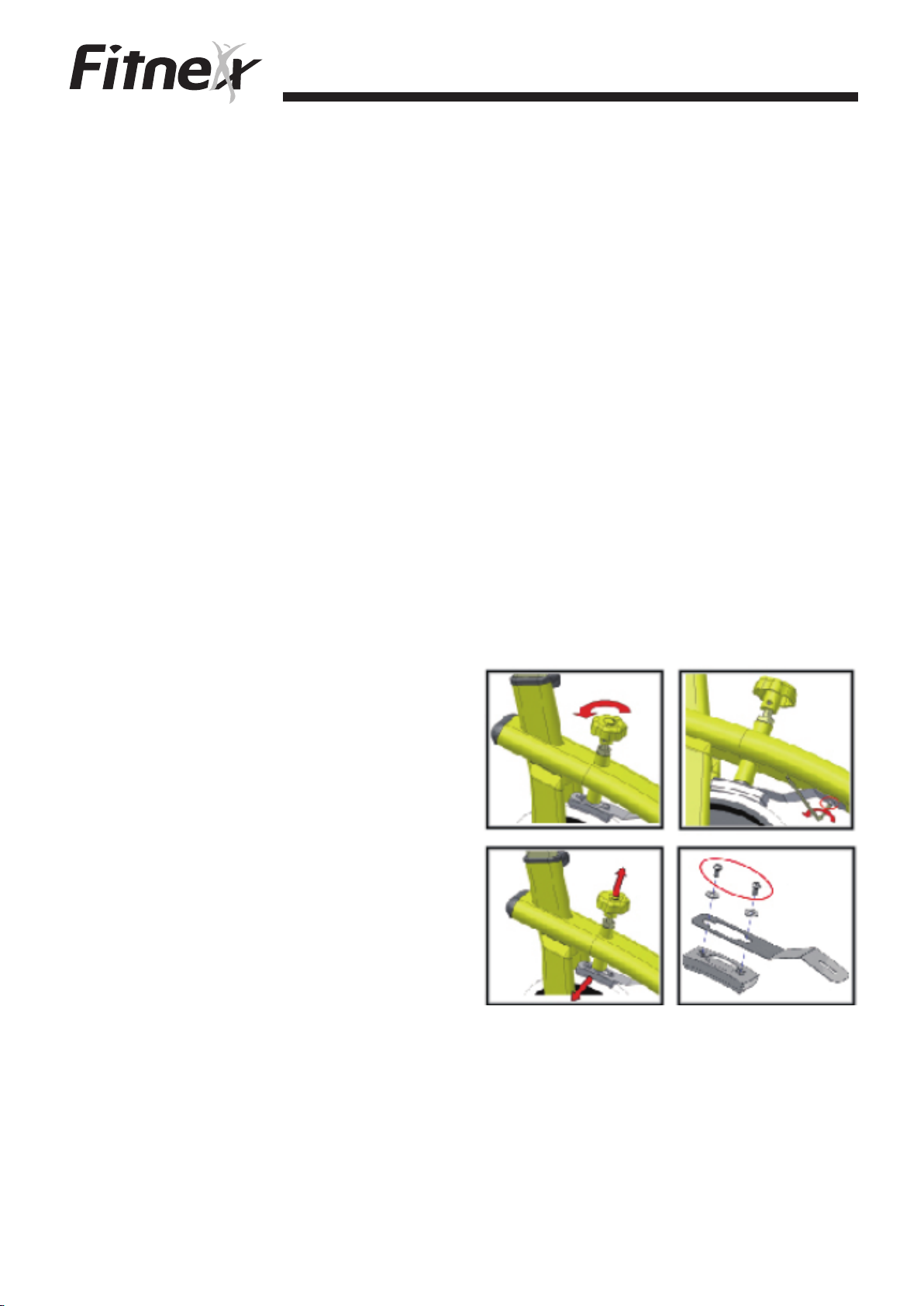
·Change the brake pad for X5:
1).Loosen resistance knob by turning
counterclockwise to the end.
2).Use the hex wrench to loosen the
hex screw which is circled.
3a).Pull the resistance knob up.
3b).Take off the resistance pad from
side.
4).Loosen two screws of the brake
by screwdriver, and remove the
brake pad.
5).Install the brake pad on the brake, and then tighten two screws to fix the pad.
6).Install the brake back and secure by tightening the hex screw.
Note:
Please check the brake pad regular and replace if needed to ensure safety.
4
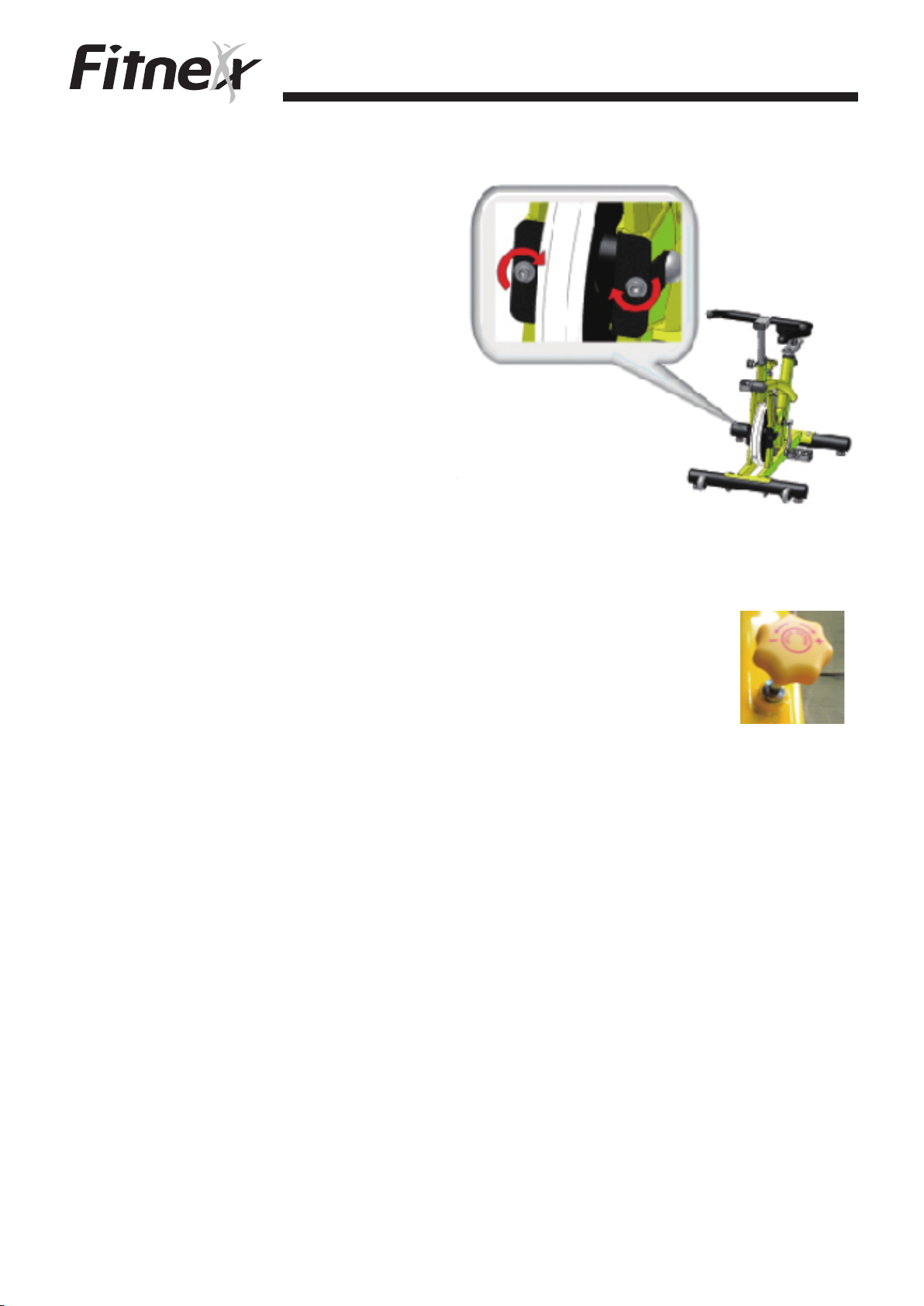
· How to adjust drive belt for X5.
1). Adjust two hex screws by hex
wrench. Turn clockwise for
tightening the belt. Turn
counterclockwise for loosing the
belt.
2). When adjusting, you may adjust one
side first, and then adjust the other side.
Note:
Both hex screws need to be adjusted in same direction
and same range. Only adjust one side might cause the belt un-balance.
X5
· Resistance control:
Pedaling resistance is controlled by the resistance brake system
knob located below the handlebar. Resistance adjustments can
be made while riding to vary the intensity of your workout.
To increase resistance, turn the brake knob clockwise (+).
To decrease resistance, turn the brake knob counterclockwise (-).
To stop flywheel abruptly, push down the brake knob directly.
· Warning:
The flywheel momentum of the cycle will keep the pedals turning even after
the user stops pedaling, or in the event the user’s feet slip off the pedals.
DO NOT DISMOUNT THE CYCLE OR REMOVE YOUR FEET FROM
THE PEDALS UNTIL BOTH THE PEDALS AND THE FLYWHEEL
HAVE STOPPED COMPLETELY. Failure to comply may lead to loss of
control and serious personal injury.
5

X5
You may stop the cycle by using any of the following methods:
· Pedal more slowly until the pedals come to a complete stop.
· Increase the resistance by turning the push brake system knob clockwise
(+) until the pedals come to a complete stop.
· Push down on the push brake system knob until the pedals come to a
complete stop.
· Assembly of Bike:
Please refer to the separately enclosed manual for the assembly of the bike.
· Seat Height and Handlebar height Adjustment:
Turn the knob counterclockwise to loose. Raising or
lowing the seat post or handlebar post until the best
position. Turn the knob clockwise direction to tighten
the seat post or the handlebar post until the post is
secured. The post can not pull over the “STOP” mark
or the lowest hole of the post. It means the least
contact area between the frame and the post.
· Seat Adjustment:
Turn the L shape knob counterclockwise, and then move
the seat fore or back to your most comfortable position.
Turn L shape knob clockwise to tighten the seat.
Note:
No handlebar adjustment for X5.
· Clean the bike:
Wipe up sweat after exercising in order to maintain the best condition
of the bike.
6

PEDAL TIGHTENING ATTENTION
PEDAL TIGHTENING
Users must take care when assembling their bike to ensure that the pedals
are securely tightened. Failure to properly tighten the pedals may lead to
loosening of the pedal during use, damage to the pedal crank arm, and
possible injury. Damage to crank arms from improperly fastened pedals is
not a warrantable item.
There is a left and right pedal.
The right pedal is marked with
an “R” on the pedal shaft. The
right pedal will thread clockwise
X5
and the left pedal will thread
counterclockwise (towards
the front the bike each side)
into the crank arm. Take care to ensure the pedal is threaded properly and
not cross-threaded. Cross-threading will damage the crank arm.
Ensure the pedal is as tight as
possible to the crank. A 15mm
wrench is included with each
bike that fits over the flat part
of the pedal shaft. Regularly
check the tightness of your
pedals. Crank arm damage due
to pedals loosening and
stripping the threads is not a warrantable item.
7

OVERVIEW
XT5
POWER SWITCH
The power switch is located on the side of the treadmill near the power
cord. The power switch has two positions - ON and OFF. The display
console will beep when the treadmill is plugged in and the power switch
is pressed ON.
CIRCUIT BREAKER RESET
The circuit breaker is located next to the power switch. Should an
electrical overload occur due to a surge in electricity or other situation,
the circuit breaker will disconnect to prevent any damage from occurring
to the treadmill.
If the treadmill suddenly stops with no lights visible nor beep
the circuit breaker. To reset the circuit breaker press the button firmly.
The display console should restart and a beep should be heard.
heard, reset
CAUTION
If the power cord is warm to the touch a problem may exist with the
electrical outlet in which the treadmill is plugged. It may be necessary to
plug the treadmill into a different outlet.
POWER CORD
Plug the power cord into a properly grounded electrical outlet, keep
power cord clean of treadmill wheels during operation. Replace the
power cord if it is damaged or pinched. Damage to the power cord could
result in a fire hazard or cause personal injury through electrical shock.
8
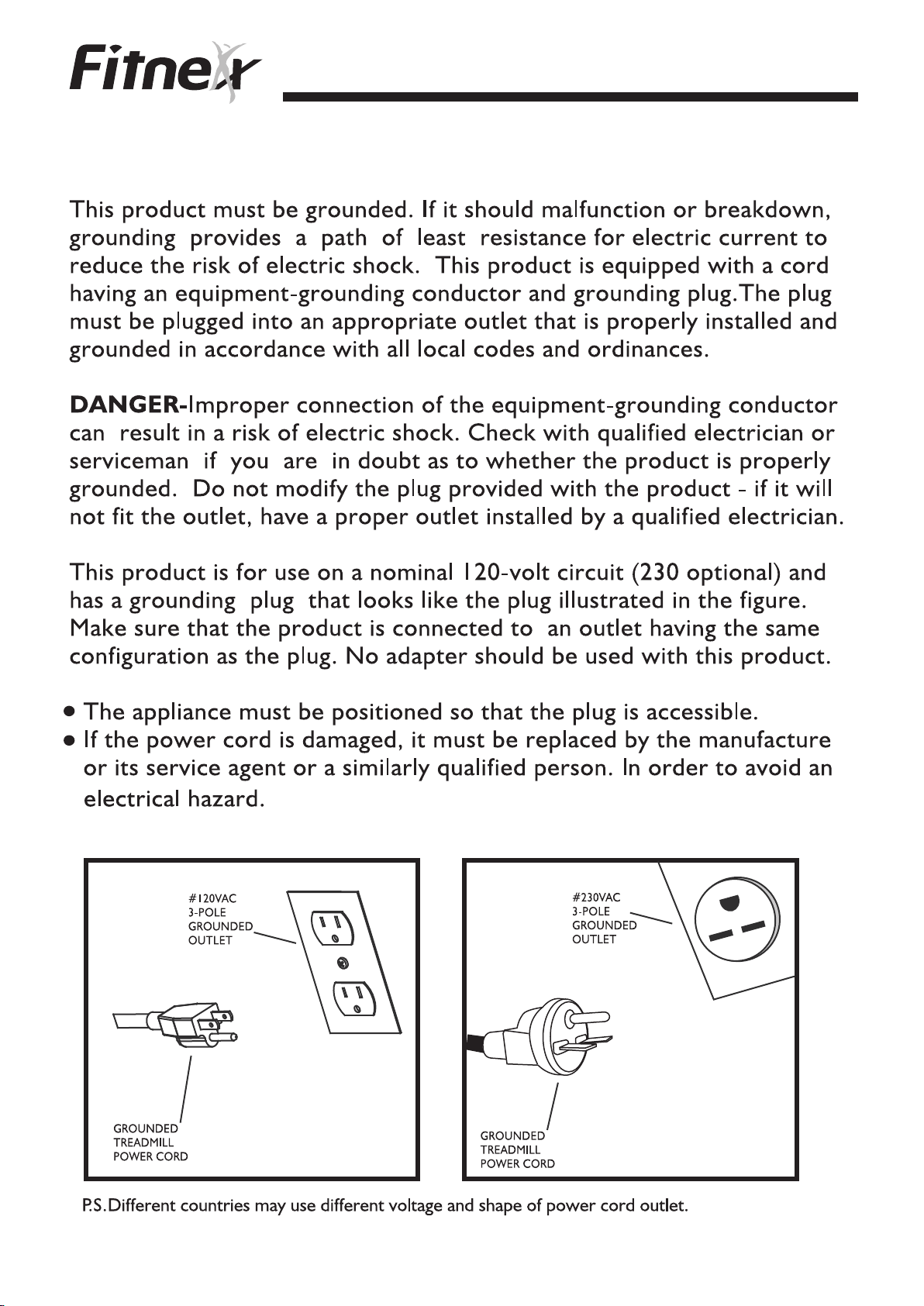
GROUNDING INSTRUCTIONS XT5
9

FCC W
ARNING-POSSIBLERADIO
XT5
/T
NOTE: This
15 of the FCC rules. These limits are designed to provide reasonable
protection against harmful interference in a residential installation.
changes
for the compliance could void the user's authority to operate the
equipment. This equipment generates, uses and can radiate radio
frequency energy and, if not installed and used in accordance with the
instructions, may cause harmful interference to radio communications.
However, there is no guarantee that the interference will not occur in
a particular installation. If this equipment does cause harmful radio
interference to radio or television reception, which can be determined
by turning the equipment off and on, you are encouraged to try to
correct the interference by one or more of the following measures:
or modifications not expressly
equipment
has been tested and found to comply with Part
ELEVISION
approved by the party responsible
I
NTERFRERENCE
Any
Reorient or relocate the receiving antenna
Increase space between the equipment
Plug the equipment into two electrical outlet
located on separate circuits
Consult an exercise equipment dealer or an
experienced radio/TV technician for help
Class R (Residential): Private or non-commercial use
10

INSTALLATON XT5
Your FITNEX treadmill is intended for use in the country to which it
was shipped. Electrical supplies outside of this country may differ and
may not be compatible with the product. Please consult Customer
Support or your dealer before using the treadmill in a
When choosing a location for the treadmill, pick a location that is
unobstructed. The treadmill must have the following clearance.
Non-entry side of treadmill - Minimum of 8 inches (20cm)
Entry side of treadmill - Minimum of 36 inches (90cm)
Front of the treadmill - Minimum of 12 inches (30cm)
Behind treadmill - Minimum of 6 feet (180cm)
different country.
These spacing requirements are mandatory for the safe use of the
treadmill. If an accident should occur, you must have sufficient space
to move away from the treadmill.
The
treadmill must be properly grounded
reduces the risk of shock or damage to the treadmill. The
plug is equipped with a grounding conductor that must be used with
an electrical outlet installed in accordance to all local codes and
ordinances. DO NOT use a temporary adapter that bypasses this
function. This will stop the safety equipment from functioning
and may void your warranty.
DO NOT MODIFY the plug provided with this product. If it will not fit an
electrical outlet, have a proper outlet installed by a qualified electrician.
prior to use. Proper grounding
powercord's
properly
11

XT5
/
��
12

INFORMATION WINDOW
TIME Indicates time in minute and seconds(mm:ss).
Indicates exercising distance of user’s workout.DISTANCE
XT5
SPEED
CALORIES
LAPS
PULSE
PROGRAM
Fitnex/Fitness Master Inc., cannot guarantee that the heart rate
measurement system on any Fitnex product will work for all users in
Indicates speed of user’s workout.
(Either miles or kilometers)
Indicates accumulated calories burned during
user’s workout.
Indicates how many runs of the playground
on the console user runs.
Indicates heart rate, beats per minute during
user’s workout.
Indicates program of user’s workout.
all instances. The accuracy of heart rate measurement will vary based
on a number of factors, for example the user's physiology and age. Plus
external interference and other factors may influence heart rate
acquisition and processing.
13
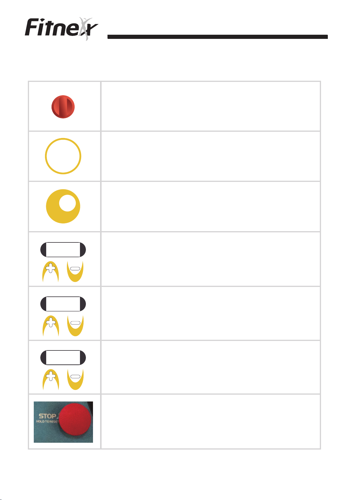
BUTTON INTRODUCTION
Pulling the safety key stops the treadmill
immediately.
XT5
START
ENTER
MODE
TIME
DISTANCE
Start workout/Enter data.
Display switch/select program and confirm.
Increase/Decrease workout time.
Increase/Decrease workout distance.
SPEED
Increase/Decrease workout speed.
Stop workout.
User can reset the treadmill by pressing and
holding for 3 seconds.
14
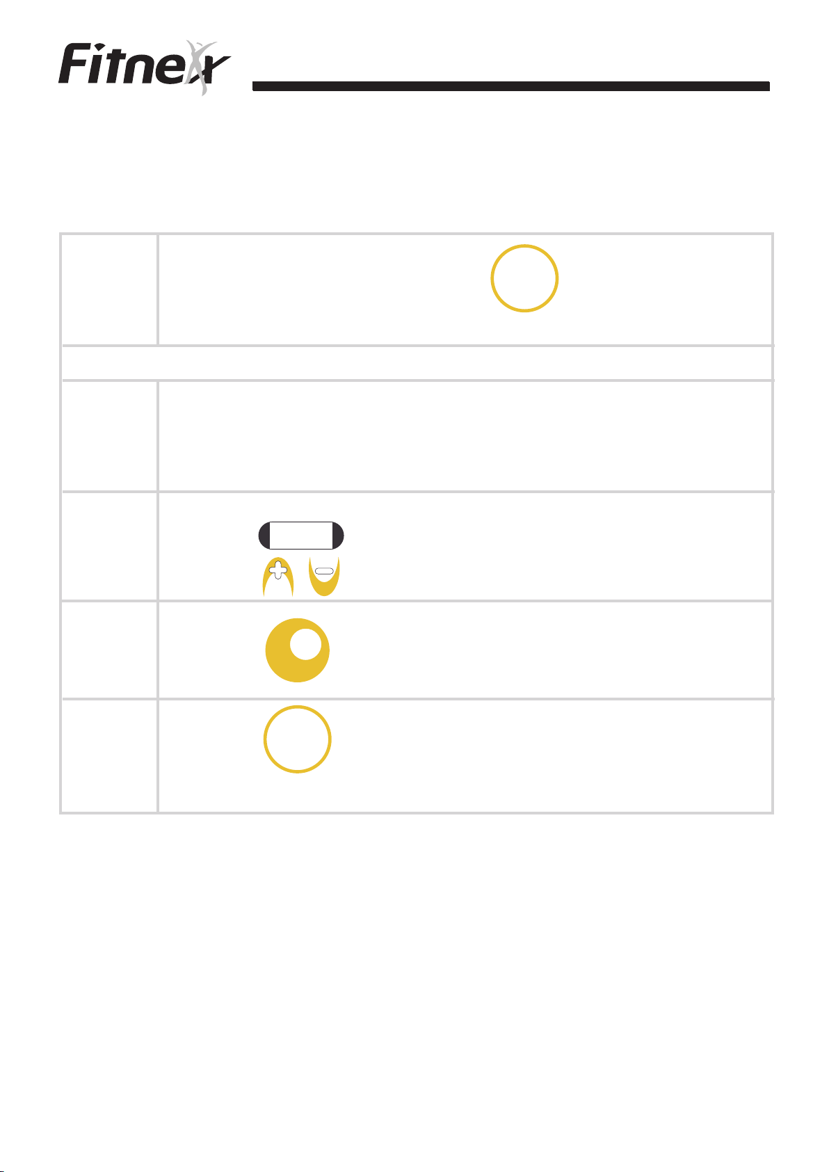
P1: MANUAL
XT5
Step 1
Step 1
Step 2
Step 3
Turn on the power and press “ ”. The treadmill
START
ENTER
counts down 3 seconds, then start workout.
or
Turn on the power and press any button to enter
mode/time settings.
SPEED
Press “ ” to choose P1.
Press “ ” to set time.
MODE
Step 4
Press “ ” . The treadmill counts down 3 seconds,
START
ENTER
then start workout.
15
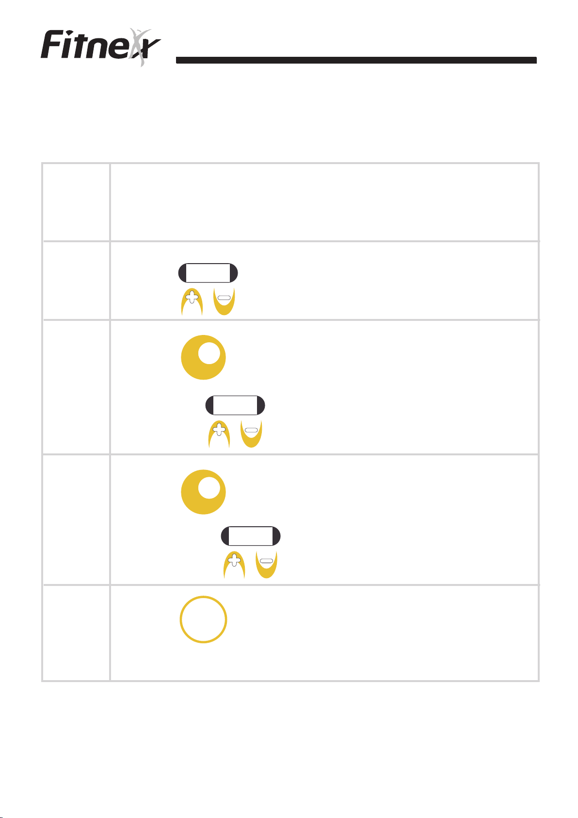
P2: CARDIO
Step 1
XT5
Turn on the power and press any button to enter
mode/time settings.
SPEED
Step 2
Step 3
Step 4
Press “ ” to choose P2.
MODE
Press “ ” to set level. L1~L3 can be set by
SPEED
pressing “ ” .
MODE
Press “ ” to set time. Time can be adjusted
TIME
by pressing “ ” . Default value is 24:00.
Step 5
Press “ ” . The treadmill counts down 3
START
ENTER
seconds, then start workout.
16

P3: FAT BURN
Turn on the power and press any button to enter
Step 1
mode/time settings.
XT5
SPEED
Step 2
Step 3
Step 4
Press “ ” to choose P3.
MODE
Press “ ” to set level. L1~L3 can be set
SPEED
by pressing “ ”.
MODE
Press “ ” to set time. Time can be adjusted
TIME
by pressing “ ” . Default value is 48:00.
Step 5
Press “ ” . The treadmill counts down 3
START
ENTER
seconds, then start workout.
17

P4: ENDURANCE
Turn on the power and press any button to enter
Step 1
mode/time settings.
XT5
SPEED
Step 2
Step 3
Step 4
Press “ ” to choose P4.
MODE
Press “ ” to set level. L1~L3 can be set by
SPEED
pressing “ ” .
MODE
Press “ ” to set time. Time can be adjusted
TIME
by pressing “ ”. Default value is 40:00.
Step 5
Press “ ” . The treadmill counts down 3
START
ENTER
seconds, then start workout.
18
P5: INTERVAL
Turn on the power and press any button to enter
Step 1
mode/time settings.
XT5
SPEED
Step 2
Step 3
Step 4
Press “ ” to choose P5.
MODE
Press “ ” to set level. L1~L3 can be set by
SPEED
pressing “ ” .
MODE
Press “ ” to set time. Time can be adjusted
TIME
by pressing “ ”. Default value is 32:00.
Step 5
Press “ ” . The treadmill counts down 3
START
ENTER
seconds, then start workout.
19

XT5
NOTE:
1.During workout, user can adjust workout speed and elevation by
pressing “ ” of speed and elevation.
2. During workout, if user presses “ ”, speed will
decrease to 0 and elevation will be stayed at the level which user
workouts. If user re-start exercising, workout program will keep
moving, but speed will decrease to 0.5MPH/0.8KPH. After
pressing “ ”, no button is pressed in 5 minutes, the
treadmill will back to standby mode.
3. During workout, user can press and hold “ ” for 3
seconds, the treadmill will back to standby mode.
ERROR CODE
E1: No speed signal.
E6: Incline operation error.
E7: Decrease or Increase of incline motor beyond mechanism safety range.
20

TEST MODE
XT5
Step 1
Step 2
Step 3
Step 4
Press “ ” and “ ” together and
START
ENTER
hold for 3 seconds until the console flashes.
Press “ ” to test all LED.
Press “ ” to test LED.
Press “ ” to test LED.
MODE
MODE
MODE
MODE
Press “ ” to test all buttons. (If button function
Step 5
Step 6
Step 7
is good, when press, user will hear a beep voice and
see a number on the window.)
Press “ ” to test I/O mode.
Press “ ” to test again or press “ ”
MODE
MODE
START
ENTER
and “ ” and hold for 3 seconds to back
to standby mode.
21

Steps for spraying lubricant on the run belt.
Step 1: Power off.
Step 2: Inspect run belt. Lift run
belt as left picture shows. Touch
running area’s back of run belt
by hand to feel if lubricant
enough on the back of run belt.
If run belt needs to be lubricated,
XT5
please take a wiper to clean run
deck and roller.
Step 3:
Lift right side of belt and spray
lubricant as left picture showed.
When spraying, your hand should
pull the run belt to make it turn
as you spray the belt.
Notice:
When spray lubricant,
please spray in center area.
Please don’t spray in side
area.
22

Steps for spray lubricant on the run belt.
Step 4:
Lift left side of belt and spray
lubricant as left picture showed.
When spraying, your hand should
pull the run belt to make it turn
as you spray the belt.
XT5
Notice:
When spray lubricant, please
spray in center area. Please
don’t spray in side area.
Step 5: Power on.
Press “START”, and increase speed to 1MPH(1.6 KPH). Have
a person walk on the treadmill to help run belt absorbtion.
Please notice:
DO NOT make the treadmill run at a high speed just spraying
lubricant. If lubricant is not absorbed, lubricant will spray out onto
the drive motor and MCB.
Remark:
1.For each time maintenance, spray 30-50 cc. lubricant is suggested.
2.Suggested time to spray lubricant:
Accumulated distance is 1250 mile (2000km).
23
XB5/XE5/XST5
24

Function choice.
For RESET to clean the value to be zero.
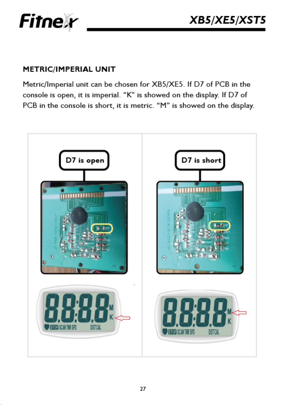
DISPLAY INFORMATION
XB5/XE5/XST5
Information Description
Scans through each function values
SCAN
TIME
SPEED
DISTANCE
CALORIES
every 6 seconds.
View elapsed time in your workout.
Displayed as Minutes:Seconds
(00:00~99:59)
Displayed as miles per hour or
kilometers per hour.
Displayed as miles or kilometers.
View distance traveled during a
workout.
Displayed as estimates accumulated
calories burned during workout.
XB5 XE5 XST5
VV V
VV V
V V
V V
VV V
PULSE
COUNT
TOTAL
COUNT
Displayed as user’s pulse. Pulse can
only be detected when user grasps
contact heart rate bars.
Displayed as steps user exercises
during workout.
Displayed as accumulated steps.
(It will be back to 0 when the
console runs out of power.)
25
VV
V
V

XB5/XE5/XST5
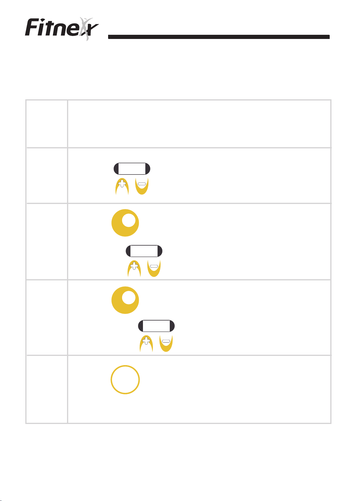
OPERATIONS
Functions Description XB5 XE5 XST5
Press the button until SCAN appears on
SCAN
TIME
SPEED
the screen. The console automatically
scans through each value every 6 seconds
on the display.
Press the button until TMR appears on
the LCD. The display will show your
actually workout time.
Press the button until SPD appears on the
LCD. The display shows current workout
speed.
V V
VV V
VV V
DISTANCE
CALORIES
PULSE
COUNT
TOTAL
COUNT
STOP
RESET
Press the button until DST appears on the
LCD. The display shows distance
traveled during workout.
Press the button until CAL appears on the
LCD. The display shows calories burned
during workout.
Press the button until PULSE appears on
the LCD. The display shows detected
pulse during workout.
Press the button until CNT appears on
the LCD. The display shows steps during
workout.
Press the button until TOTAL CNT
appears on the LCD. The display shows
accumulated steps during workout
If no RPM signal is detected, STOP shows
on the LCD. All functions will stop counting.
Press and hold the button for 2 seconds to
get the function value to be 0.
V V
VV V
VV
V
V
VV V
VV V
When you start to exercise or press the
AUTO
ON/OFF
button on the console, it turns on. If you
don’t have any action or signal input to
the console in 4 minutes, the power will
turn off automatically.
NOTE
Two batteries(SUM3 size AA 1.5V) are used for the console.
26
VV V

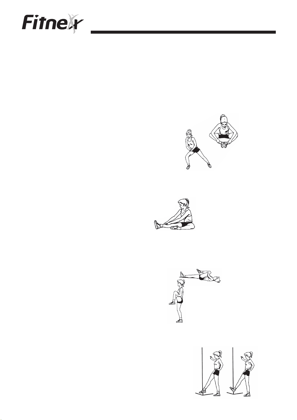
Stretching and Flexibility
Lower Back, Hips, Groin, and Hamstrings
1. Stand with the feet about shoulder- width apart and pointed
straight ahead. If you are pretty flexible and need more of a
stretch, cross one leg in front of the other for a few stretches,
then switch legs.
2. Slowly bend forward from the hips, always keeping your
knees slightly bent.
3. Stretch only to the point where you feel a tugging in the
back of your legs.
Side Bends
1. Stand with your feet about shoulder - width apart and toes
pointed straight ahead. Keep your knees slightly bent, one
hand on
head. Slowly bend at your waist to one side, toward the
hand on your hip.
2. Extend both arms overhead.
Hold your right hand with your
left hand and bend slowly to
the left, using your left arm
to pull the right arm gently
over the head and down
toward the ground.
3. Repeat with other side.
your hip; extend your other arm up and over your
Quadriceps (front of thigh)
1. Lying on our stomach, pull the heel toward your buttocks with
the opposite hand. Keep the thigh of the leg being stretched
close to the leg on the floor.
2. The same stretch can be
done standing. Do not allow
the thigh to come in front of
you and so not
at the waist.
3. Do this exercise twice - once
on each leg.
bend forward
28
Stretching and Flexibility
Groin (inside of thigh)
1. Sit on the
Gently push knees down toward the floor with
your elbows.
2. Stand with your feet three to four feet apart and
turned out slightly.
3. Keep the knee of the leg to be stretched straight,
and bend the opposite knee as you move
your body toward the bent leg.
Keep your toes pointed forward.
4. Repeat using the other leg
Hamstrings (back side of upper leg)
1. Sit with one knee bent and the leg to be stretched
out straight. Reach for the toes of the straight leg
with the right hand and
then the left hand.
2. Repeat with the other leg.
floor with the soles of your feet together.
Gluteus (back of hip)
1. Lie on your back. Pull one knee up to your chest while
keeping the opposite leg down on the floor with the
knee straight.
2. The same may be done standing.
3. Repeat with the other leg.
Anterior Tibials (front of shin)
1. Stand with all of your weight on one leg. Extend the
opposite leg forward and flex and
point at the ankle.
2. Repeat with the other leg.
29

For XT5
Item
Console
Mounting
Bolts
Frame
Console
Safety St op
Power Cord
Running Belt
Top
Running Belt
Tension
Running Belt
Rear
Adjustable
foot
V Belt
Daily Weekly Monthly Quarterly Bi-annual
Inspect
Clean
Clean
Test
Inspect
Inspect
Clean
(Vacuum)
Inspect
Inspect
Adjust
Adjust
Inspect
Inspect
Motor Pulley
Running
Belt
Lubricant
For XE5/XST5
Item
Console
Console
Mounting
Bolts
Out covers
Fasteners
Bearings
Clean
Suggested time to spray lubricant:
Accumulated distance is 1250 miles (2000km).
After Use Weekly Monthly Quarterly Bi-annual
Clean
Clean
Inspect and
tighten
Inspect and
lubricate
Inspect
Inspect and
tighten
Footpads
Inspect and
tighten
30

For XB5
Item
Console
Console
Mounting
Bolts
Handlebar
connection
Out covers
Foot straps
Seat fasteners
Seat post
Crank arms
After Use Weekly Monthly Quarterly Bi-annual
Clean
Inspect tighten
as required
Clean
Inspect
Inspect tighten
as required
Inspect tighten
as required
Inspect
Inspect and
tighten
Apply light coat
of lubricant
31

Warranty
1. The Warranty applies to the original owner and is extended to
cover the cost of part(s) repair and/or replacement and does not
include associated freight charges. Proof of purchase must be
demonstrated.
2.Warranty is non transferable. If you are in USA, the warranty card
must be completed and sent back to Fitness Master Inc. to
complete registration. If you are out of USA, please contact your
local dealer about the warranty.
3. Labor coverage is provided only if an authorized Fitnex dealer or
the Fitnex factory representative dose the work.
4.Any reimbursement for travel outside of the dealers’ normal service
or coverage area will be the responsibility of the customer.
5.Warranty dose not cover failure due to improper assembly, installation
or use.
6.This warranty does not cover customer instruction, installation, set up
or adjustment. Note that tread belt tensioning and tracking are the
responsibility of the user and are not covered by this warranty. User
is also responsible for reasonable and necessary maintenance. Failure
to maintain proper tread belt tracking and tensioning will void this
warranty.
7. This warranty will not be extended to any product whose serial
number has been removed, altered, or defaced.
8. This warranty dose not cover damage or equipment failure caused
by, or resulting from accident, misuse, abuse, improper assembly
or installation, un-authorized modificaton, or failure to provide
reasonable and necessary care as outlined in the owner’s maunal.
32

 Loading...