

Page 1

Wireless
Day & Night
MJPEG
Network Camera
Advanced Installation Guide
CS303A, ICS303A, CS303B, CS303C, ICS303B,
ICS303C, HNIPC150W, CAS-336, CAS-336W,
AICC700W, HNC3W, IPC1210
Version 1.0
Page 2

PREFACE
Thank you for purchasing the MJPEG Network Camera, a powerful
and high-quality image network camera. The camera can be installed
as a standalone system within your application environment easily
and quickly, and supports remote management function so that you
can access and control it using a Web browser on your PC.
This Advanced Installation Guide provides you with the instructions
and illustrations on how to use your camera, which includes:
Chapter 1 Introduction to Your Camera describes the features of
the camera. You will also know the components and
functions of the camera.
Chapter 2 Hardware Installation helps you install the camera
according to your application environment. You can use
this camera at home, at work, at any where you want.
Chapter 3 Accessing the Camera lets you start using your camera
without problem. The camera can be set up easily and
work within your network environment instantly.
Chapter 4 Configuring the Camera guides you through the
configuration of the camera using the web browser on
your PC.
Chapter 5 Appendix provides the specification of the camera and
some useful information for using your camera.
NOTE The illustrations and configuration values in this guide are for
reference only. The actual settings depend on your practical
application of the camera.
- 1 -
Page 3

Contents
Preface .......................................................................................... 1
Chapter 1 Introduction To Your Camera ....................................... 3
1.1 Checking the Package Contents ...................................... 3
1.2 Getting to Know Your Camera ......................................... 4
1.3 Features and Benefits ...................................................... 6
1.4 System Requirement ........................................................ 7
Chapter 2 Hardware Installation .................................................... 8
2.1 Installing the Camera Stand ............................................. 8
2.2 Connecting the Camera to LAN/WLAN ............................ 9
2.3 Applications of the Camera ............................................ 10
Chapter 3 Accessing the Camera ............................................... 11
3.1 Using IPFinder ............................................................... 11
3.2 Accessing to the Camera ............................................... 12
3.3 Configuring the IP Address of the PC ............................ 15
Chapter 4 Configuring the Camera ............................................. 16
4.1 Using the Web Configuration ......................................... 16
4.2 Using Smart Wizard ....................................................... 17
4.3 Basic Setup .................................................................... 20
4.4 Network Settings ............................................................ 23
4.5 Setting up Video & Audio ............................................... 32
4.6 Event Server Configuration ............................................ 34
4.7 Motion Detect ................................................................. 37
4.8 Event Config ................................................................... 38
4.9 Tools ............................................................................... 41
4.10 Information ..................................................................... 43
Chapter 5 Appendix .................................................................... 44
A.1 Specification ................................................................... 44
A.2 Glossary of Terms .......................................................... 46
- 2 -
Page 4

CHAPTER 1
INTRODUCTION TO YOUR CAMERA
1.1 Checking the Package Contents
Check the items contained in the package carefully. You should have
the following:
5 One Wireless MJPEG Network Camera.
5 One AC Power Adapter.
5 One Camera Stand.
5 One Ethernet Cable (RJ-45 type).
5 One Installation CD-ROM.
5 One Quick Installation Guide.
NOTE Once any item contained i s dama ged or missing, contact the
authorized dealer of your locale.
- 3 -
Page 5

1.2 Getting to Know Your Camera
Internal Microphone
allows the camera to
receive sound and voice.
Lens Assembly
Power LED indicates
the camera is powered
on with the steady
amber light.
Link LED indicates
the camera’s network
connectivity with the
flashing green light.
Front View
- 4 -
Page 6
A
p
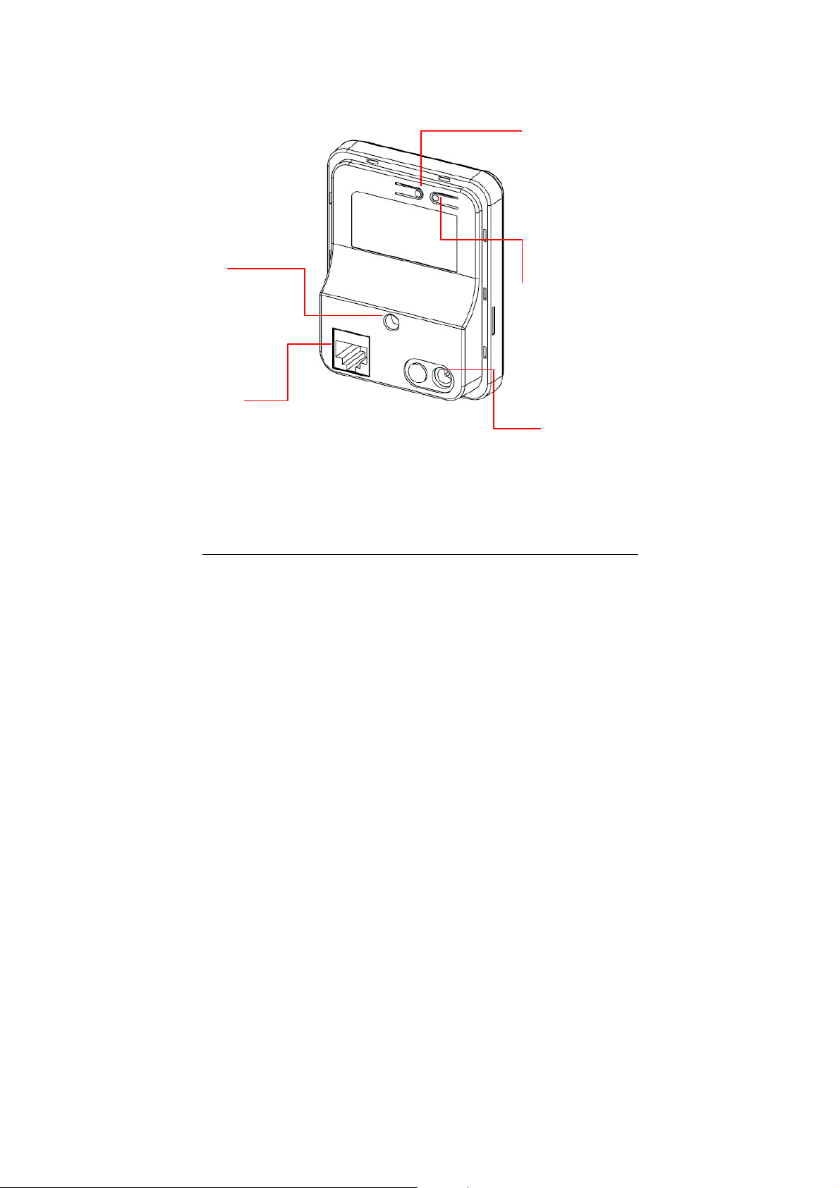
Screw Hole is used
to connect the camera
stand.
Ethernet Cable Connector
is used to connect the
network cable, which supports
the NWay protocol so that the
camera can detect the
network speed automatically.
WPS Button* (for
wireless model)
is used to protect your
wireless network and
for easy wireless
connection setu
Reset Button will restart
the camera when it is
pressed quickly; when it is
long pressed for five
seconds, the camera will
resume the factory default
settings.
DC Power Connector
is used to connect the
C power adapter, in
order to supply power
to the camera.
.
* For more information of the WPS button, refer to the instruction of the Web
Configuration, Network >> Wireless >> WPS Setting.
Rear View
- 5 -
Page 7

1.3 Features and Benefits
MJPEG codec Supported
The camera provides you with VGA images by the MJPEG
codec technology, allowing you to adjust image size and quality,
and bit rate according to the networking environment.
1-way Audio Capability
The built-in microphone of the camera provides on-the-spot
audio via the Internet, allowing you to monitor the on-site voice.
Remote Control Supported
By using a standard Web browser or the bundled UltraView Pro
software application, the administrator can easily change the
configuration of the camera via Intranet or Internet. In addition,
the camera can be upgraded remotely when a new firmware is
available. The users are also allowed to monitor the image and
take snapshots via the network.
Multiple Platforms Supported
The camera supports multiple network protocols, including
TCP/IP, SMTP e-mail, HTTP, and other Internet related
protocols. Therefore, you can use the camera in a mixed
operating system environment, such as Windows Vista and
Windows 7.
Multiple Applications Supported
Through the remote access technology, you can use the
cameras to monitor various objects and places for your own
purposes.
For example, babies at home, patients in the hospital, offices
and banks, and more. The camera can capture both still images
and video clips, so that you can keep the archives and restore
them at any time.
- 6 -
Page 8

1.4 System Requirement
Networking
- LAN: 10Base-T Ethernet or 100Base-TX Fast
Ethernet, Auto-MDIX
- WLAN: IEEE 802.11b/g/n
Accessing the Camera using Web Browser
- Platform: Microsoft® Windows® 2000/XP/Vista/Win7
- CPU: Intel Pentium III 800MHz or above
- RAM: 512MB
- Resolution: 800x600 or above
- User Interface: Microsoft® Internet Explorer 6.0 or above;
Apple Safari 2 or above; Mozilla Firefox
2.00 or above; Google Chrome
Accessing the Camera using UltraView Pro
- Platform: Microsoft® Windows® XP/Vista/Win7
- Resolution: 1024x768 or above
Hardware Requirement:
- 1~8 cameras: Intel Core 2 Duo 2GB RA M
- 9~32 cameras: Intel Core 2 Quad 4GB RAM
NOTE If you connect multiple ca meras to monitor various places
simultaneously, you are recommended to use a computer with
higher performance.
- 7 -
Page 9
CHAPTER 2
HARDWARE INSTALLATION
2.1 Installing the Camera Stand
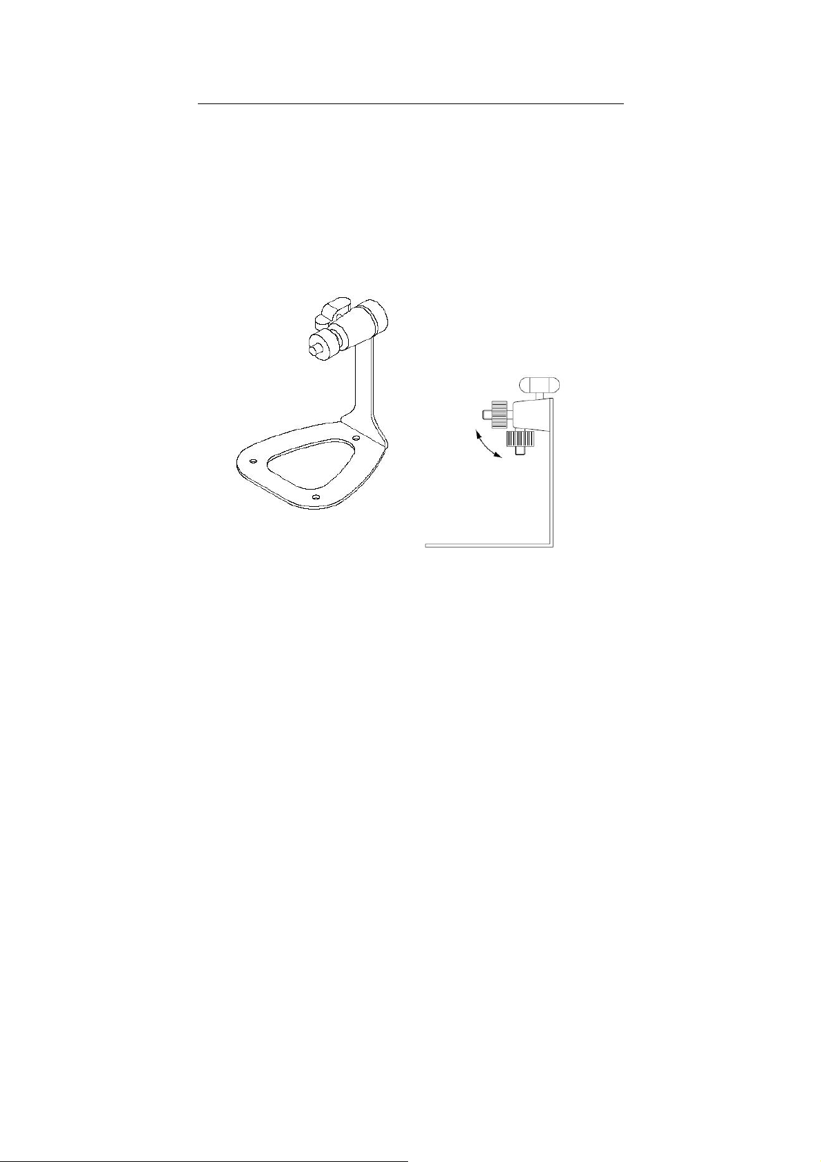
The camera comes with a camera stand, which uses a swivel ball
screw head to lock to the camera’s screw hole. When the camera
stand is attached, you can place the camera anywhere by mounting
the camera through the three screw holes located in the base of the
camera stand.
The Camera Stand
- 8 -
Page 10

2.2 Connecting the Camera to LAN/WLAN
Use the provided Ethernet cable to
connect the camera to your local
area network (LAN).
When you connect the AC power
adapter, the camera is powered on
automatically. You can verify the
power status from the Power LED
on the front panel of the camera.
Once connected, the Link LED
starts flashing green light and the
camera is on standby and ready
for use now.
If you use a wireless network in your application environment,
you need to attach the included external antenna to the camera.
When the camera is powered on, the camera will automatically
search any access point with “default” SSID.
Connecting the Ethernet Cable
NOTE (for wirele ss model) If the camera cannot to your wireless
network, you need to install the camera in LAN and proceed
with WLAN settings.
- 9 -
Page 11
2.3 Applications of the Camera
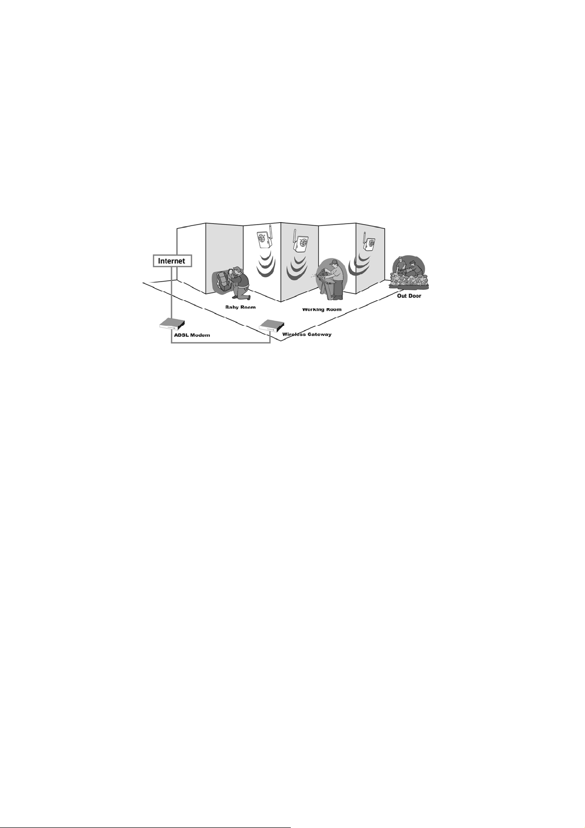
The camera can be applied in multiple applications, including:
Monitor local and remote places and objects via Internet or
Intranet.
Capture still images and video clips remotely.
Upload images or send email messages with the still images
attached.
The following diagram explains one of the typical applications for
your camera and provides a basic example for installing the camera.
*
*Please enclosed by waterproof
housing when using in outdoor
Home Applications
- 10 -
Page 12

CHAPTER 3
ACCESSING THE CAMERA
3.1 Using IPFinder
The camera comes with a conveniently utility, IPFinder, which is
included in the Installation CD-ROM, allowing you to search the
camera on your network easily.
1. Insert the Installation CD-ROM into your computer’s CD-ROM
drive to initiate the Auto-Run program.
2. Click the IPFinder item to launch the utility. The control panel will
appear as below.
Display the connected
camera(s)
Double click to link the
camera
Click About to get the Version information of IPFinder.
Click Link to connect the selected camera.
Click Change IP to modify the IP address of the selected camera.
Click Search to find the IP address of the connected camera(s).
Click Exit to close the utility.
3. Once you get the IP address of the camera, launch the Web
browser or UltraView Pro to access your camera.
- 11 -
Page 13
3.2 Accessing to the Camera
Whenever you want to access the camera:
1. Since the default configuration of the camera is DHCP mode
enabled, you are recommended to launch IPFinder to search the
IP address that is assigned to the camera by the DHCP server,
and then click Link to access the camera via the Web browser.
2. If Network Camera can't get IP Address under DHCP mode, the
default IP Address will be 192.168.0.30.
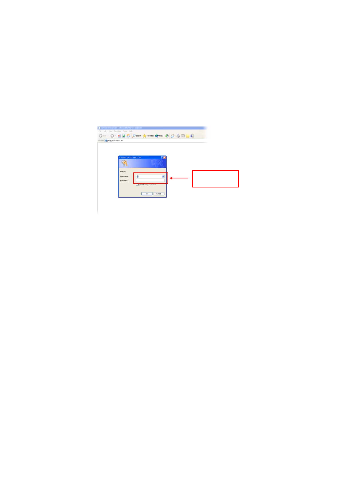
3. When the login window appears, enter the default User name
(admin) and password (admin) and press OK to access to the
main screen of the camera’s Web Configuration.
Enter the User
name and
Password.
NOTE If you are initially access to the camera, you will be ask to
install a new plug-in for the camera. Permission request
depends on the Internet security settings of your computer.
Click Yes to proceed.
- 12 -
Page 14

After you login into the Web Configuration of the camera, the main
page will appear as below:
Zoom In Buttons
Live View/Setup Switch
Function Buttons
Language
Camera Information
Live View Image
The main page of the Web Configuration provides you with many
useful information and functions, including:
Camera Information
– Display the camera’s location and the
current date & time. The information can be modified in the Web
Configuration.
Language
– Select your favorite displayed language for the
system.
Live View Image
– Displays the real-time image of the
connected camera.
Live View/Setup Switch
– Click Setup to configure the camera.
For details, see Chapter 4 and Click the Live View button to
return to the Main screen to view the live view image.
Function Buttons
– Use these buttons to control the video
functions.
- 13 -
Page 15

z Manual Record allows you to record and save a video clip.
z Snapshot allows you to capture and save a still image.
z Browse allows assign the destination folder to store the
video clips and still images.
z Listen allows you to receive the on-site sound and voice
from the camera.
Zoom In Buttons
image by 1x, 2x, and 3x.
NOTE If your PC use Microsoft Vista platform. Maybe you can’t find
these recorded files what stored by Snapshot or Manual
Record. That you need to disable the protected mode of
Security in the IE Browser. Please follow as below Steps:
1. Open IE Browser
2. Select ToolsÆ Internet Options
3. Select Security
4. Disable the “Enable Protected Mode” then press OK
– Click the buttons to zoom in the live view
- 14 -
Page 16

3.3 Configuring the IP Address of the PC
If you are failed to access to the camera, please check the IP
address of your computer. When you connect the camera to your
computer directly to proceed with configuration of the camera, you
need to set up the IP addresses to be in the same segment for the
two devices to communicate.
1. On your computer, click Start > Control Panel to open the
Control Panel window.
2. Double-click Network Connection to open the Network
Connection window.
3. Right-click Local Area Connection and then click Properties
from the shortcut menu.
4. When the Local Area Connection Properties window appears,
select the General tab.
5. Select Internet Protocol [TCP/IP] and then click Properties to
bring up the Internet Protocol [TCP/IP] Properties window.
6. To configure a fixed IP address that is within the segment of the
camera, select the Use the following IP address option. Then,
enter an IP address into the empty field. The suggested IP
address is 192.168.0.x (x is 1~254 except 30), and the
suggested Subnet mask is 255.255.255.0.
7. When you are finished, click OK.
- 15 -
Page 17
CHAPTER 4
CONFIGURING THE CAMERA
4.1 Using the Web Configuration
You can access and manage the camera through the Web browser
and the provided software application UltraView Pro. This chapter
describes the Web Configuration, and guides you through the
configuration of the camera by using the web browser.
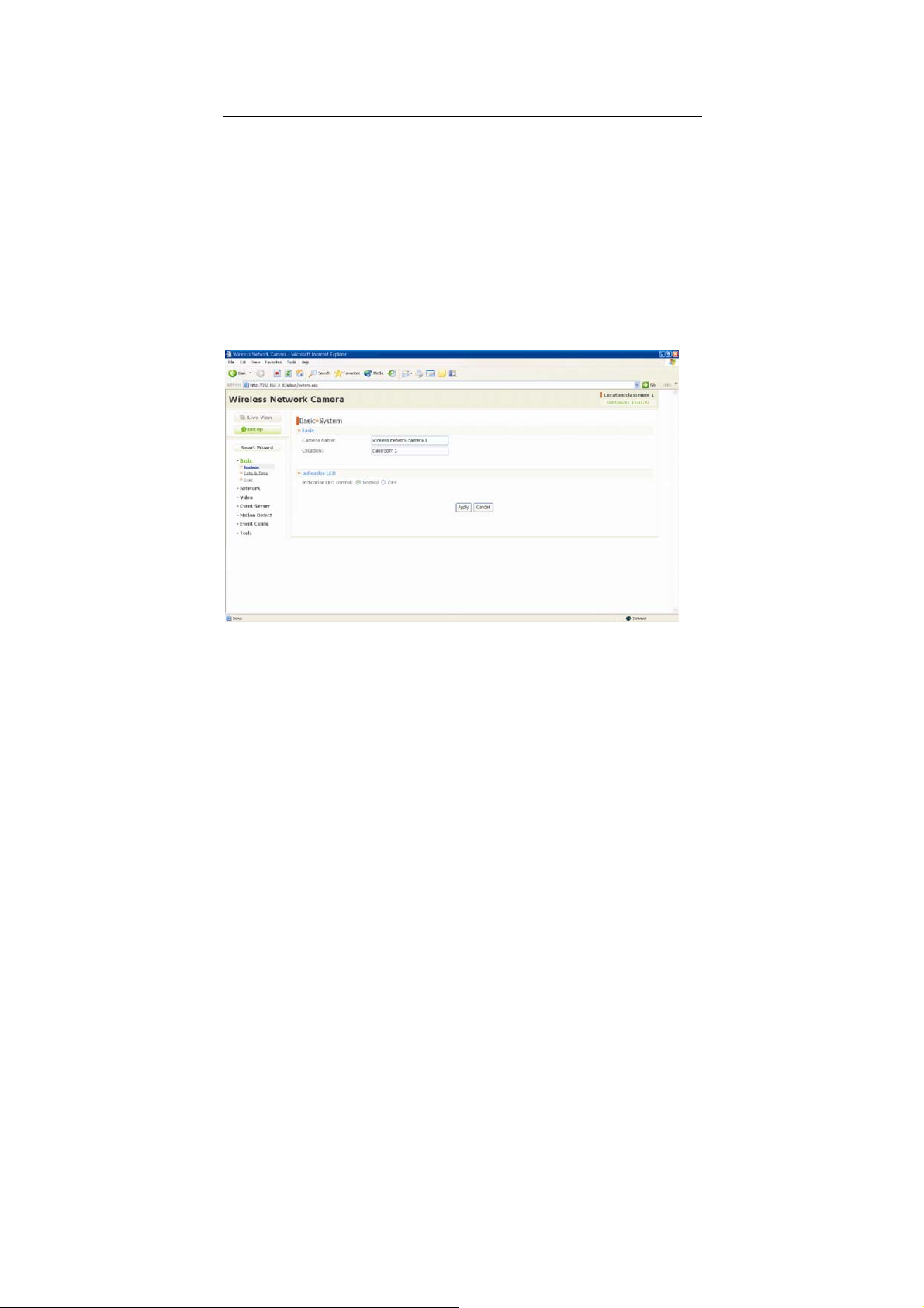
To configure the camera, click Setup on the main page of Web
Configuration. The Web Configuration will start from the Basic page.
The Web Configuration contains the settings that are required for the
camera in the left menu bar, including Smart Wizard, Basic,
Network, Video, Event Server, Motion detect, Event Config,
Tools, and Information.
- 16 -
Page 18
4.2 Using Smart Wizard
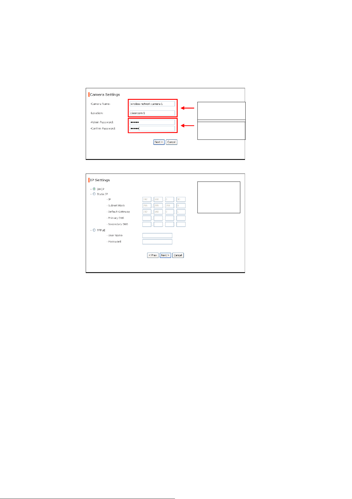
The camera’s Smart Wizard lets you configure your camera easily
and quickly. The wizard will guide you through the necessary
settings with detailed instructions on each step.
To start the wizard, click Smart Wizard in the left menu bar.
Step 1. Camera Settings
Enter the name for
the camera and
place.
Enter the
administrator
password.
Step 2. IP Settings
Select the IP
setting according
to your network:
DHCP, Static IP,
or PPPoE.
- 17 -
Page 19
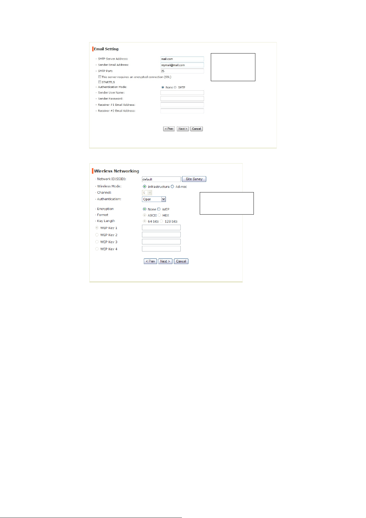
Step 3. Email Settings
Enter the required
information to be
able to send email
with image.
Step 4. Wireless Networking (for wireless model)
Complete the required
settings for wireless
networking.
- 18 -
Page 20
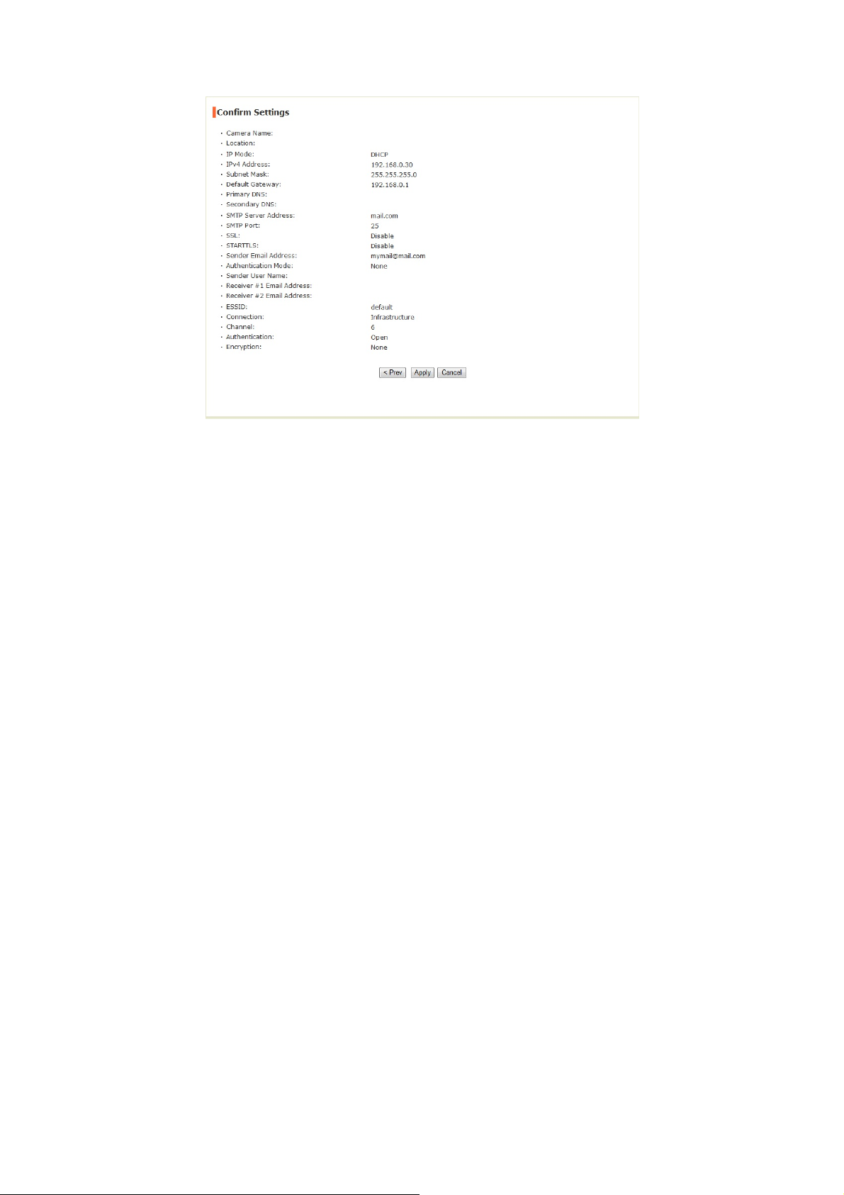
Step 5. Confirm Settings
This step shows the configuration of your camera. When you confirm
the settings, click Apply to finish the wizard and reboot the camera.
Otherwise, click Prev to go back to the previous step(s) and change
the settings; or click Cancel to end the wizard and di scard the
changes.
- 19 -
Page 21
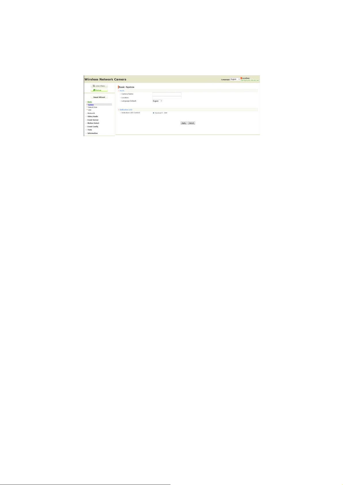
4.3 Basic Setup
The Basic menu contains three sub-menus that provide the system
settings for the camera, such as the Camera Name, Location, Date &
Time, and User management.
Basic >> System
Basic
- Camera Name: Enter a descriptive name for the camera.
- Location: Enter a descriptive name for the location used by
the camera.
Indication LED
This item allows you to set the LED illumination as desired.
There are two options: Normal and OFF.
Basic >> Date & Time
Date & Time
- TimeZone: Select the proper time zone for the region from the
pull-down menu.
- 20 -
Page 22

- Synchronize with PC: Select this option and the date & time
settings of the camera will be synchronized with the connected
computer.
- Synchronize with NTP Server: Select this option and the
time will be synchronized with the NTP Server. You need to
enter the IP address of the server and select the update
interval in the following two boxes.
- Manual: Select this option to set the date and time manually.
Basic >> User
Administrator
To prevent unauthorized access to the camera’s Web
Configuration, you are strongly recommend to change the
default administrator password. Type the administrator password
twice to set and confirm the password.
General User
- User Name: Enter the user’s name you want to add to use the
camera.
- Password: Enter the password for the new user.
When you are finished, click Add/Modify to add the new user
to the camera. To modify the user’s information, select the one
you want to modify from UserList and click Add/Modify.
- UserList: Display the existing users of the camera. To delete
a user, select the one you want to delete and click Delete.
Guest
- User Name: Enter the guest’s name you want to add to use
the camera.
- Password: Enter the password for the new guest.
- 21 -
Page 23

- UserList: Display the existing guests of the camera. To delete
a user, select the one you want to delete and click Delete.
NOTE The “Gene ral User” can access the camera and control the
Function buttons of the camera’s Web Configuration; the
“Guest’ can only view the live view image from the main page
of the Web Configuration while accessing the camera. Only
the “Administrator” is allowed to configure the camera through
the Web Configuration.
- 22 -
Page 24
4.4 Network Settings
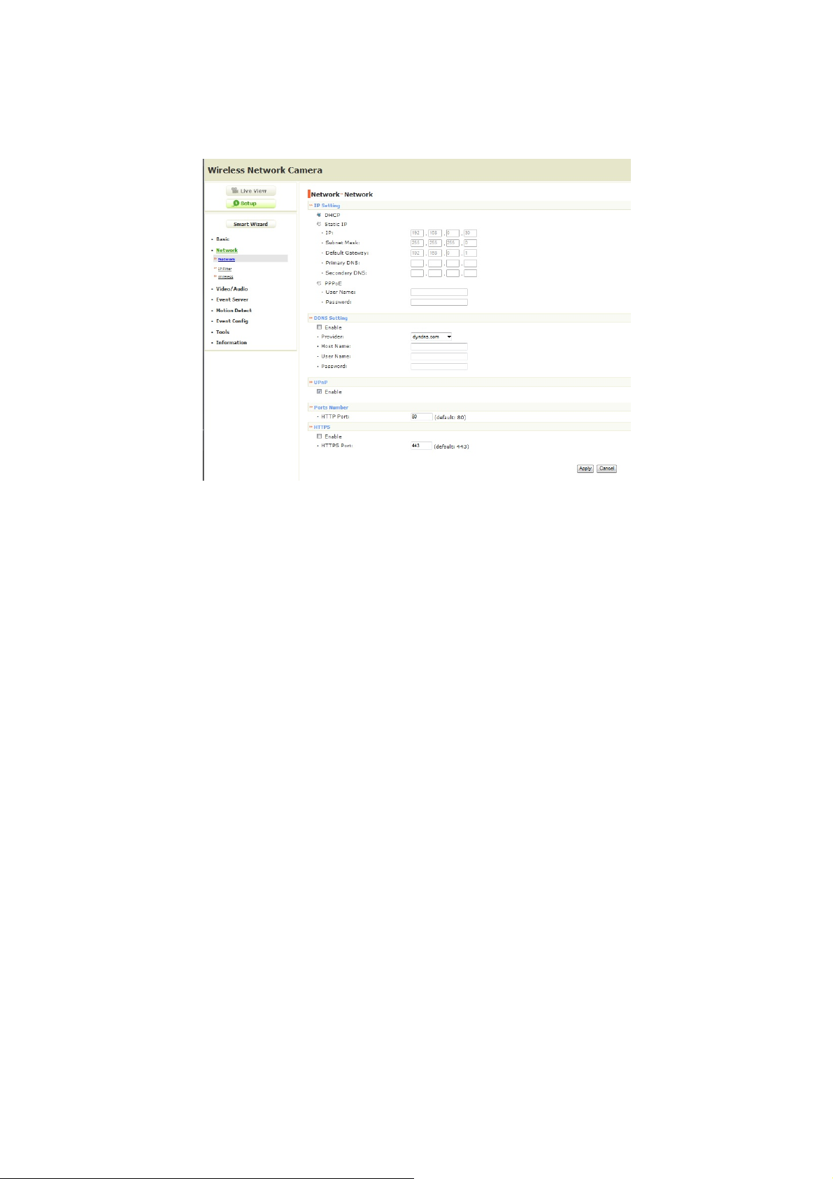
The Network menu contains three sub-menus that provide the
network settings for the camera, such as the IP Setting, DDNS
Setting, IP Filter, and Wireless (for wireless model).
Network >> Network
IP Setting
This item allows you to select the IP address mode and set up
the related configuration.
- DHCP: Select this option when your network uses the DHCP
server. When the camera starts up, it will be assigned an IP
address from the DHCP server automatically.
- 23 -
Page 25

- Static IP: Select this option to assign the IP address for the
camera directly. You can use IPFinder to obtain the related
setting values.
IP Enter the IP address of the camera. The
default setting is 192.168.0.30.
Subnet Mask Enter the Subnet Mask of the camera. The
default setting is 255.255.255.0.
Default Gateway Enter the Default Gateway of the camera.
The default setting is 192.168.0.1.
Primary/
Secondary DNS
DNS (Domain Name System) translates
domain names into IP addresses. Enter the
Primary DNS and Secondary DNS that are
provided by ISP.
- PPPoE: Select this option when you use a direct connection
via the ADSL modem. You should have a PPPoE account from
your Internet service provider. Enter the User Name and
Password. The camera will get an IP address from the ISP as
starting up.
NOTE Once the camera g et an IP addre ss from the ISP as starting
up, it automatically sends a notification email to you.
Therefore, when you select PPPoE as your connecting type,
you have to set up the email or DDNS configuration in
advance.
DDNS Setting
With the Dynamic DNS feature, you can assign a fixed host and
domain name to a dynamic Internet IP address. Select the Enable
option to enable this feature. Then, select the Provider from the
pull-down list and enter the required information in the Host Name,
User Name, and Password boxes. Please note that you have to
sign up for DDNS service with the service provider first.
- 24 -
Page 26

UPnP
The camera supports UPnP (Universal Plug and Play), which is
a set of computer network protocols that enable the device-todevice interoperability. In addition, it supports port auto mapping
function so that you can access the camera if it is behind an NAT
router or firewall. Select the Enable option to enable this feature.
Ports Number
- HTTP Port: The default HTTP port is 80.
NOTE If the camera is behi nd an NAT router of firewall, the
suggested to be used is from 1024 to 65535.
z HTTPS
- Enable: Select this option to enable HTTPS, which is a
secure protocol to provide authenticated and encrypted
communication within your network.
- HTTPS Port: Assign a HTTPS port in the text box. The
default HTTPS port is 443.
Network >> IP Filter
The IP Filter setting allows the administrator of the camera to limit
the users within a certain range of IP addresses to access the
camera. To disable this feature, select the Disable option; otherwise,
select the Accept option to assign the range of IP addresses that are
allowed to access the camera, or select the Deny option to assign
the range of IP addresses that are blocked to access the camera.
z Disable: Select this option to disable the IP Filter function of
the camera.
z Accept
- IPv4: Assign a range of IP addresses that are allowed to
access the camera by entering the Start IP address and
- 25 -
Page 27

End IP address options. When you are finished, click Add
to save the range setting. You can repeat the action to
assign multiple ranges for the camera.
- IPv6: Enter the IP Address that is allowed to access the
camera.
z Deny
- IPv4: Assign a range of IP addresses that are blocked to
access the camera by entering the Start IP address and
End IP address options. When you are finished, click Add
to save the range setting. You can repeat the action to
assign multiple ranges for the camera.
- IPv6: Enter the IP Address that is not allowed to access the
camera.
For example, when you enter 192.168.0.50/192.168.0.80 in
Start/End IP Address of Accept > IPv4, the user whose IP address
located within 192.168.0.50 ~ 192.168.0.80 will be allowed to access
the camera. On the other hand, if you enter the IP range in
Start/End IP Address of Deny > IPv4, the user whose IP address
located within the range will not be allowed to access the camera.
- 26 -
Page 28
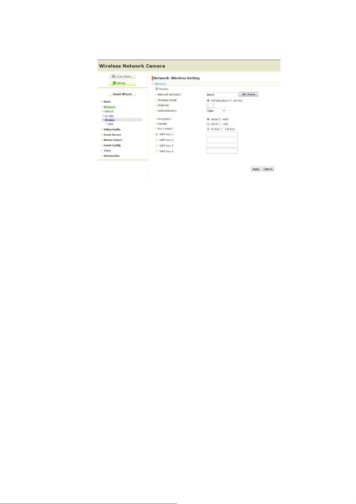
Network >> Wireless Setting (for wireless model)
The camera supports WLAN while you use the wireless network.
Select the Enable option to enable this feature.
Wireless
- Network ID (SSID}: Keep the default setting of this option to
connect the camera to any access point under the
infrastructure network mode. To connect the camera to a
specified access point, set a SSID for the camera to
correspond with the access point’s ESS-ID. To connect the
camera to an Ad-Hoc wireless workgroup, set the same
wireless channel and SSID to match with the computer’s
configuration.
Click Site Survey to display the available wireless networks,
so that you can easily connect to one of the listed wireless
networks.
- 27 -
Page 29
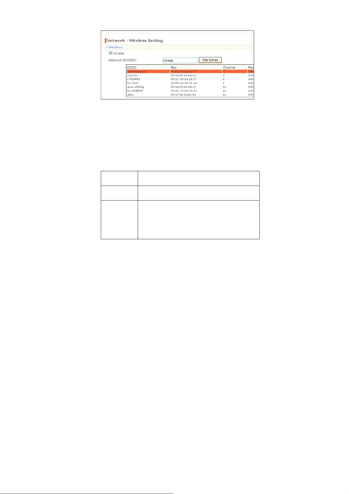
List of searching results
- Wireless Mode: Select the type of wireless communication for
the camera: Infrastructure or Ad-Hoc.
- Channel: Select the appropriate channel from the list.
- Authentication: Select the authentication method to secure
the camera from being used by unauthorized user: Open,
Shared-key, WPA-PSK, and WPA2-PSK. The following table
explains the four options:
Open The default setting of Authentication mode,
which communicates the key across the network.
Shared-key Allow communication only with other devices
with identical WEP settings.
WPA-PSK/
WPA2-PSK
WPA-PSK/WPA2-PSK is specially designed for
the users who do not have access to network
authentication servers. The user has to manually
enter the starting password in their access point
or gateway, as well as in each PC on the
wireless network.
If you select Open or Shared-key as the Authentication mode,
you need to complete the following settings:
- 28 -
Page 30

Encryption: Select the WEP option to enable the data
encryption feature to secure the camera within the wireless
network.
Format: Once you enable the Encryption feature, you need
to determine the encryption format by selecting ASCII or
HEX. ASCII format causes each character you type to be
interpreted as an eight-bit value. Hex format causes each
pair of characters you type to be interpreted as an eight-bit
value in hexadecimal (base 16) notation.
Key Length: Select the WEP key length you use: 64 bits or
128 bits.
WEP Key 1/2/3/4: Enter the WEP key(s) in the following
boxes.
If you select WPA-PSK or WPA2-PSK as the Authentication
mode, you need to complete the following settings:
Encryption: Select TKIP or AES. TKIP (Temporal Key
Integrity Protocol) changes the temporal key every 10,000
packets to insure much greater security than the standard
WEP security. AES (Advanced Encryption Standard) is used
to ensure the highest degree of security and authenticity for
digital information.
Pre-Shared Key: This is used to identify each other in the
network. Enter the name in the box, and this name must
match the Pre-shared key value in the remote device.
- 29 -
Page 31
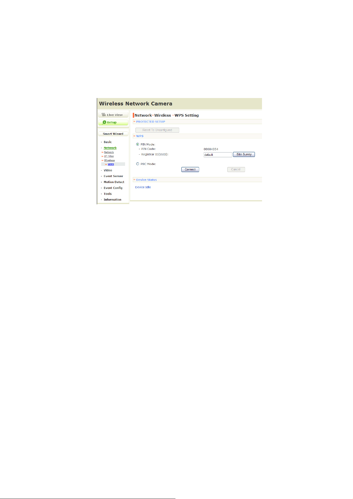
Network >> Wireless >> WPS Setting (for wireless
model)
WPS (Wi-Fi Protected Setup) sets a new standard of Wi-Fi security,
providing a simplified secure network setup solution for the end
users. WPS can be enabled by the following two options:
1. PIN Mode
2. PBC Mode (or WPS button on the device, depending on
hardware design)
PROTECTED SETUP
Press the Reset To Unconfigured button to reset the WPS
configuration of the camera.
WPS
- PIN Mode: The PIN (Personal Information Number) mode
builds the connection by entering the PIN Code directly.
a. Click the PIN Mode option.
- 30 -
Page 32

b. Click Site Survey button to select the router (or access
point) you want to connect.
c. Click the Connect button to start WPS function of the
camera.
d. You need to enter the PIN Code displayed on the camera
to the router (or access point) within 120 seconds to
complete the setup.
- PBC Mode: The PBC (Push-Button-Configuration) mode
builds the connection by simply pressing a button on the
device.
a. Click the PBC Mode option.
b. Click the Connect button to start WPS function of the
camera.
TIP Instead of clicking the Connect button of Configuration
Utility, you can press the WPS button if the camera is
designed with a hardware button of WPS function.
c. You need to press the WPS button on the router (or
access point) within 120 seconds to complete the setup.
Device Status
Display the WPS configuration of the camera.
TIP The Power LED indicates the WPS connection status by:
- blinking 3 times when the connection is built successfully.
- repeating 3 times of short-short-long blink when the
connection is failed.
- 31 -
Page 33
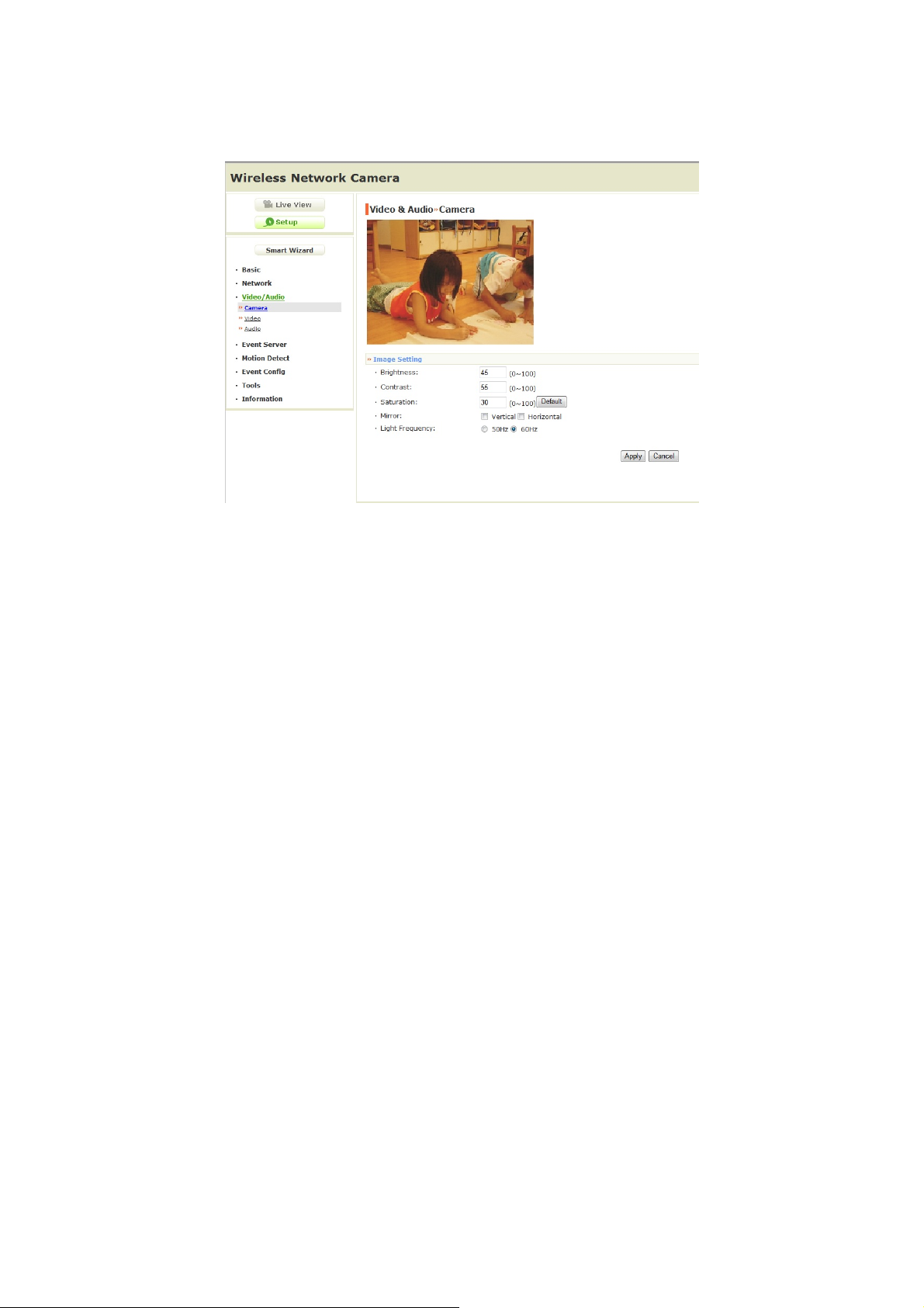
4.5 Setting up Video & Audio
The Video & Audio menu contains four sub-menus that provide the
video and audio settings for the camera.
Video & Audio >> Camera
Image Setting
- Brightness: Adjust the brightness level from 0 ~ 100.
- Contrast: Adjust the contrast level from 0 ~ 100.
- Saturation: Adjust the colors level from 0 ~ 100
TIP Click Default then Apply to restore the default settings of the
three options above.
- 32 -
.
Page 34

- Mirror: Select the Horizontal option to mirror the image
horizontally. Select the Vertical option to mirror the image
vertically.
- Light Frequency: Select the proper frequency according to
the camera’s location: 50Hz or 60Hz.
Video & Audio >> Video
MJPEG
- Video Resolution: Select the desired video resolution from
the three formats: VGA, QVGA and QQVGA. The higher
setting (VGA) obtains better video quality while it uses more
resource within your network.
- Video Quality: Select the desired image quality from five
levels: Lowest, Low, Normal, High, and Highest.
- Frame Rate: Select a proper setting depending on your
network status. The available setting value includes: 5, 10, 15,
20, or 25.
Video & Audio >> Audio
Camera Microphone In:
- Enable: Select the Enable option to enable the camera's
audio function, so that you can receive the on-site sound and
voice from the camera.
- 33 -
Page 35
4.6 Event Server Configuration
The Event Server menu contains two sub-menus that allow you to
upload images to FTP, and send emails that include still images.
When you complete the required settings for FTP, or Email, click
Test to test the related configuration is correct or not. Once the
camera connects to the server successfully, click Apply.
- 34 -
Page 36

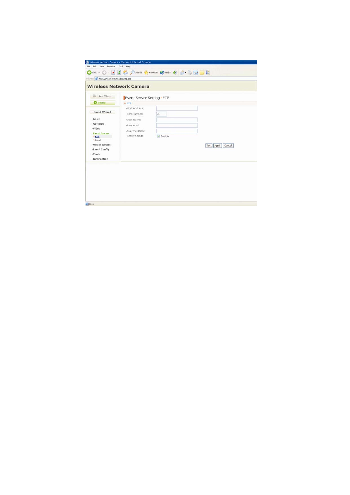
Event Server Setting>> FTP
FTP
- Host Address: Enter the IP address of the target FTP server.
- Port Number: Enter the port number used for the FTP server.
- User Name: Enter the user name to login into the FTP server.
- Password: Enter the password to login into the FTP server.
- Directory Path: Enter the destination folder for uploading the
images. For example, /Test/.
- Passive Mode: Select the Enable option to enable passive
mode.
Event Server Setting >> Email
Email
- SMTP Server Address: Enter the mail server address. For
example, mymail.com
- Sender Email Address: Enter the email address of the user
who will send the email. For example, [email protected]
- SMTP Port: Assign the SMTP port in the text box. The default
SMTP port is 25. If the mail server requires an encrypted
connection, you should check the SSL option. STARTTTLS is
an extension to plain text communication protocols. It offers a
way to upgrade a plain text connection to an encrypted (TLS or
SSL) connection instead of using a separate port for encrypted
communication.
- Authentication Mode: Select None or SMTP according to the
mail server configuration.
- Sender User Name: Enter the user name to login the mail
server.
.
.
- Sender Password: Enter the password to login the mail server.
- 35 -
Page 37

- Receiver #1 Email Address: Enter the first email address of
the user who will receive the email.
- Receiver #2 Email Address: Enter the second email address
of the user who will receive the email.
- WAN IP Change Notification: Select the option to enable the
system to notify you when the WAN IP address changed.
- 36 -
Page 38
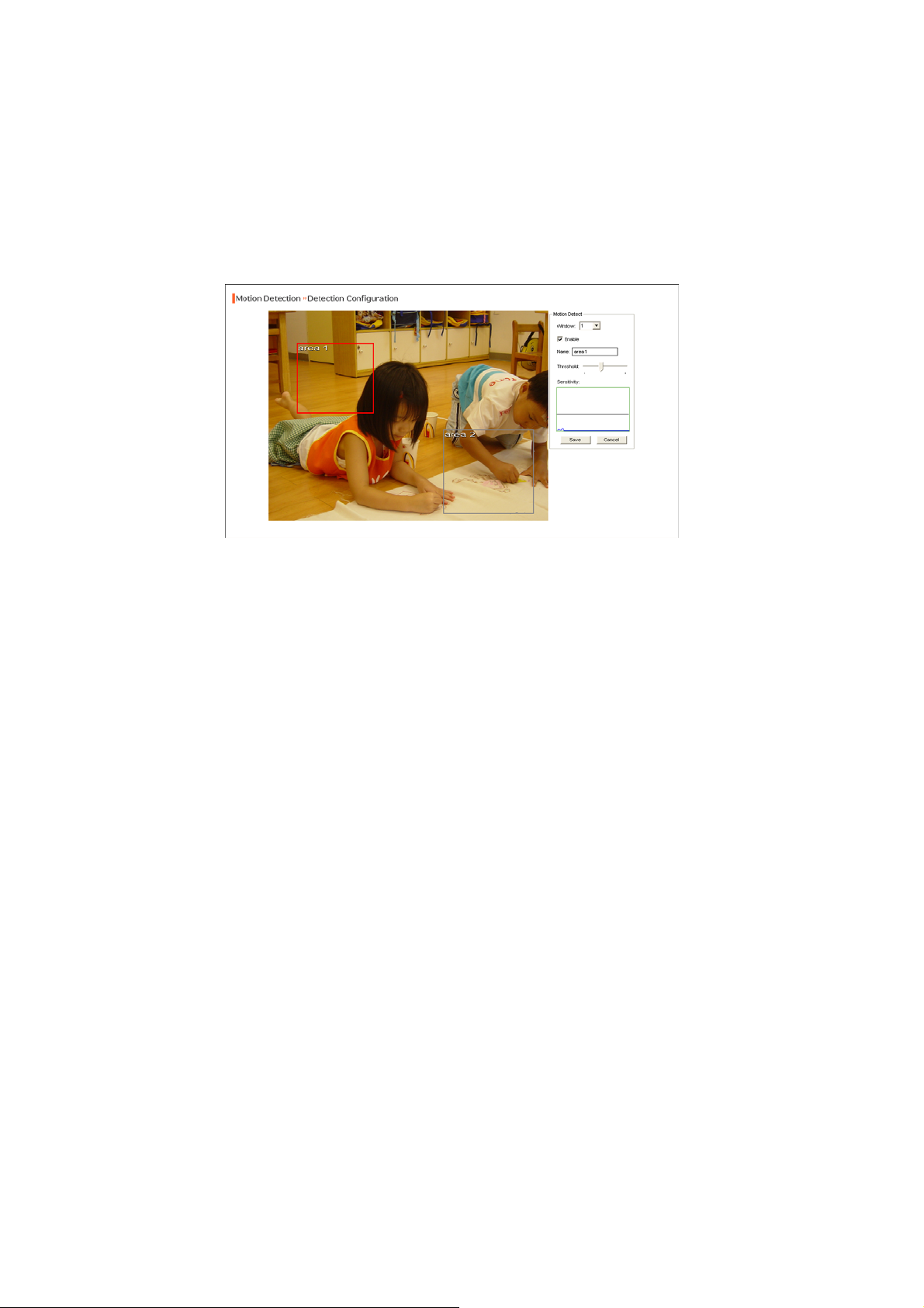
4.7 Motion Detect
The Motion Detect menu contains the command and option that
allow you to enable and set up the motion detection feature of the
camera. The camera provides two detecting areas.
To enable the detecting area, select Window 1 or 2 from the pulldown list, and then select Enable. When the detecting area is
enabled, you can use the mouse to move the detecting area and
change the area coverage.
- Name: Assign a name to the detecting area.
- Threshold: Move the slide bar to adjust the level for detecting
motion to record video.
- 37 -
Page 39
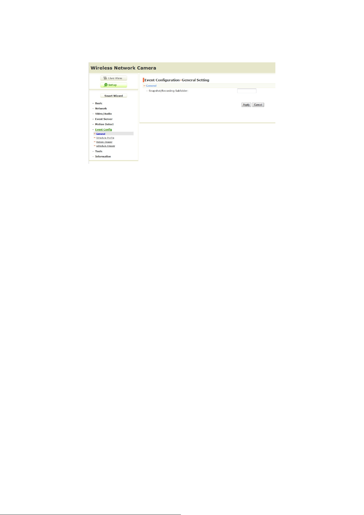
4.8 Event Config
The Event Config menu contains four sub-menus that provide the
commands to configure event profiles.
Event Configuration >> General Setting
- Snapshot/Recording Subfolder: You can assign a given
sub-folder for captured file. Otherwise, leave this option blank
to use the default setting.
- 38 -
Page 40
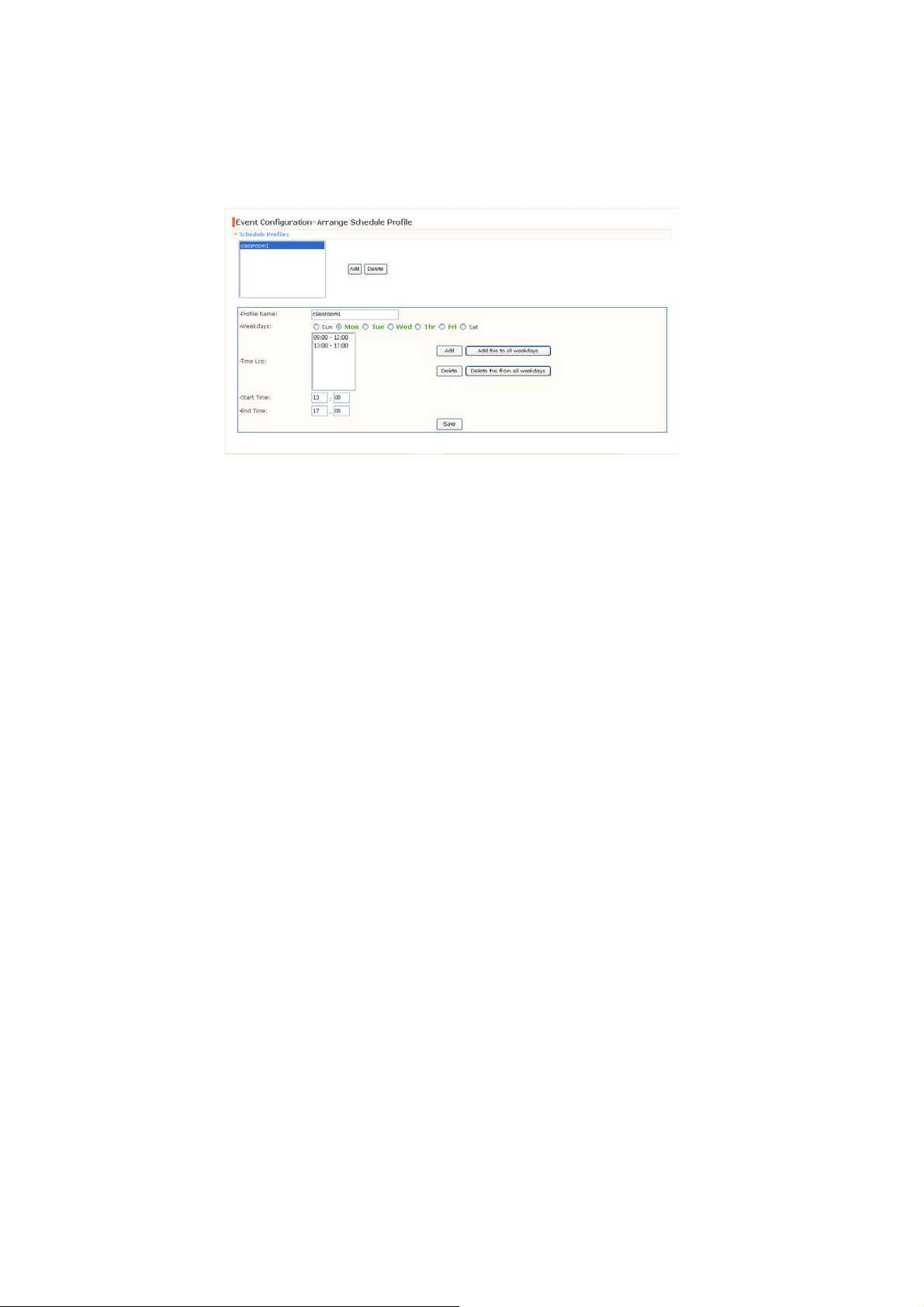
Event Configuration >> Arrange Schedule Profile
This sub-menu displays the scheduled profile(s). To customize the
profile, click Add and then enter a descriptive name for the profile in
the prompt dialog window. After entering the profile name, click OK
and the profile is added to the Schedule Profiles list. To delete the
profile, select the profile in the list and click Delete.
- Profile Name: Display the profile name that you select in the
Schedule Profiles list.
- Weekdays: Select the weekday(s) that you want to separately
assign in the schedule profile. The weekday that has been
assigned will be displayed with green color.
- Time List: Display the time period that you have assigned
within the selected weekday. To assign the same time period
to every weekday, click Add this to all weekdays; click
Delete this from all weekdays to remove the selected time
period from every weekday. Click Delete to remove the
selected time period.
- Start/End Time: Enter the start and end time and then click
Add to assign a time period within in the selected weekday.
- 39 -
Page 41

Event Configuration >> Motion Detect Trigger
Select the Enable option to enable the trigger function of the camera,
so that you can send captured images within the detecting area to
the FTP server, or email receiver. You have to configure
corresponding settings, such as FTP server and email server, to
enable this feature.
- Schedule Profile: Select a schedule profile from the pull-down
list.
- Action: Select the destination that the captured images will be
sent to: Send Email, or FTP Upload.
Event Configuration >> Schedule Trigger
You can separately configure the schedule for trigger function of the
camera by Email, or FTP. Select the Enable option on each item,
and then select a Schedule Profile from the pull-down list and set
the Interval time.
- 40 -
Page 42
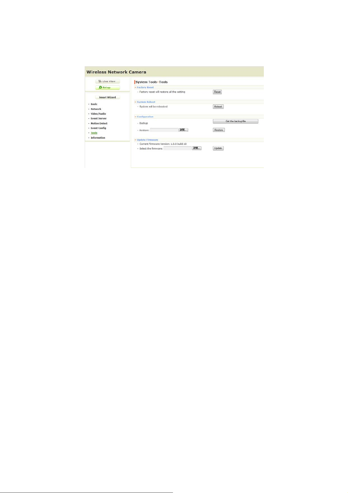
4.9 Tools
The Tools menu provides the commands that allow you to restart or
reset the camera. You can also backup and restore your
configuration, and upgrade the firmware for the camera.
Factory Reset
Click Reset to restore all factory default settings for the camera.
System Reboot
Click Reboot to restart the camera just like turning the device off
and on. The camera configuration will be retained after rebooting.
Configuration
You can save your camera configuration as a backup file on your
computer. Whenever you want to resume the original settings,
you can restore them by retrieving the backup file.
- Backup: Click Get the backup file to save the current
configuration of the camera.
- 41 -
Page 43

- Restore: Click Browse to locate the backup file and then click
Restore.
Update Firmware
This item displays the current firmware version. You can
upgrade the firmware for your camera once you obtained a latest
version of firmware.
- Select the firmware: Click Browse to locate the backup file
and then click Update.
NOTE Make su re to keep the camera connected to the power source
during the process of upgrading firmware. Otherwise, the
camera might be damaged because of failure of upgrading
firmware.
- 42 -
Page 44
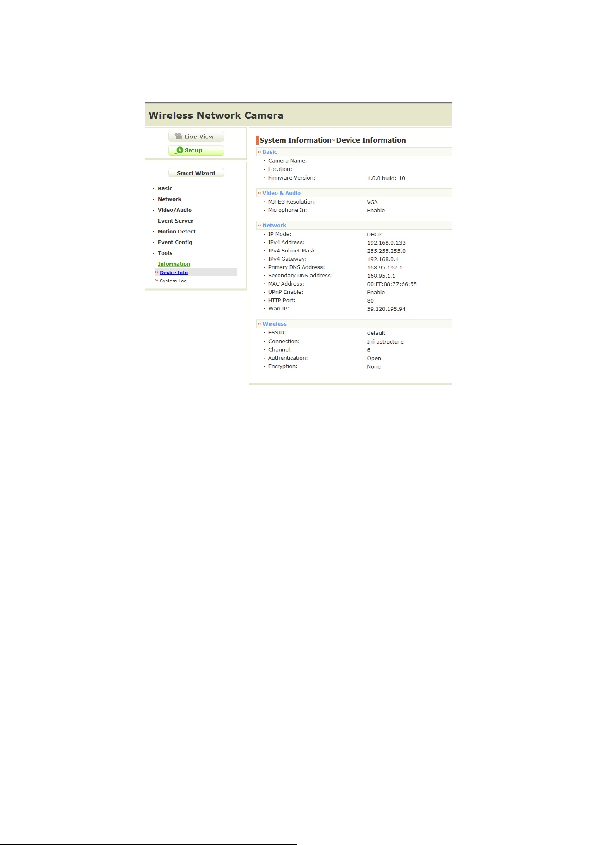
4.10 Information
The Information menu displays the current configuration and events
log of the camera.
Device Info
Display the Basic, Video, Network, and Wireless settings (for
wireless model) of the camera.
System Log
The Logs table displays the events log recorded by the system.
- 43 -
Page 45

CHAPTER 5
APPENDIX
A.1 Specification
Image Sensor
Sensor 1/4” color CMOS
Resolution 640x480
Video
Compression MJPEG
Video resolution VGA/QVGA/QQVGA; 25fps max.
System Hardware
Processor MIPS base
RAM 32MB SDRAM
ROM 4MB NOR Flash
Power DC 5V
Communication
LAN 10/100Mbps Fast Ethernet, auto-sensed,
Auto-MDIX
PoE (for PoE model) IEEE802.3af
WLAN (for wireless model) IEEE 802.11b/g/n
Protocol support TCP/IP, UDP, ICMP, DHCP, NTP, DNS,
DDNS, SMTP, FTP, HTTP, PPPoE, UPnP
User Interface
- 44 -
Page 46

LAN One RJ-45 port
Antenna (for wireless model) One external antenna
WPS (for wireless model) One WPS button
Reset One reset button
LEDs Power LED (amber); Link LED (green)
Software
OS Support Windows XP/Vista/Win7
Browser Internet Explorer 6.0 or above
Apple Safari 2 or above
Mozilla Firefox 2.00 or above
Google Chrome
Software UltraView Pro for playback/recording/
configuration features
Operating Environment
Temperature Operation: 0°C ~ 45°C
Storage: -15°C ~ 60°C
Humidity Operation: 20% ~ 85% non-condensing
Storage: 0% ~ 90% non-condensing
EMI FCC Class B, CE Class B
- 45 -
Page 47

A.2 Glossary of Terms
NUMBERS
10BASE-T
100BASE-TX
A
ADPCM
AMR
Applet
ASCII
ARP
AVI
B
BOOTP
10BASE-T is Ethernet over UTP Category III, IV, or V
unshielded twisted-pair media.
The two-pair twisted-media implementation of 100BASET is called 100BASE-TX.
Adaptive Differential Pulse Code Modulation, a new
technology improved from PCM, which encodes analog
sounds to digital form.
AMR (Adaptive Multi-Rate) is an audio data compression
scheme optimized for speech coding, which is adopted
as the standard speech codec by 3GPP.
Applets are small Java programs that can be embedded
in an HTML page. The rule at the moment is that an
applet can only make an Internet connection to the
computer form that the applet was sent.
American Standard Code For Information Interchange, it
is the standard method for encoding characters as 8-bit
sequences of binary numbers, allowing a maximum of
256 characters.
Address Resolution Protocol. ARP is a protocol that
resides at the TCP/IP Internet layer that delivers data on
the same network by translating an IP address to a
physical address.
Audio Video Interleave, it is a Windows platform audio
and video file type, a common format for small movies
and videos.
Bootstrap Protocol is an Internet protocol that can
automatically configure a network device in a diskless
workstation to give its own IP address.
- 46 -
Page 48

C
Communication
Connection
D
DHCP
DNS
Communication has four components: sender, receiver,
message, and medium. In networks, devices and
application tasks and processes communicate messages
to each other over media. They represent the sender and
receivers. The data they send is the message. The
cabling or transmission method they use is the medium.
In networking, two devices establish a connection to
communicate with each other.
Developed by Microsoft, DHCP (Dynamic Host
Configuration Protocol) is a protocol for assigning
dynamic IP addresses to devices on a network. With
dynamic addressing, a device can have a different IP
address every time it connects to the network. In some
systems, the device's IP address can even change while
it is still connected. It also supports a mix of static and
dynamic IP addresses. This simplifies the task for
network administrators because the software keeps track
of IP addresses rather than requiring an administrator to
manage the task. A new computer can be added to a
network without the hassle of manually assigning it a
unique IP address. DHCP allows the specification for the
service provided by a router, gateway, or other network
device that automatically assigns an IP address to any
device that requests one.
Domain Name System is an Internet service that
translates domain names into IP addresses. Since
domain names are alphabetic, they're easier to
remember. The Internet however, is really based on IP
addresses every time you use a domain name the DNS
will translate the name into the corresponding IP
address. For example, the domain name
www.network_camera.com might translate to
192.167.222.8.
- 47 -
Page 49

E
Enterprise
network
Ethernet
F
Fast Ethernet
Firewall
G
Gateway
Group
An enterprise network consists of collections of networks
connected to each other over a geographically dispersed
area. The enterprise network serves the needs of a
widely distributed company and operates the company’s
mission-critical applications.
The most popular LAN communication technology. There
are a variety of types of Ethernet, including 10Mbps
(traditional Ethernet), 100Mbps (Fast Ethernet), and
1,000Mbps (Gigabit Ethernet). Most Ethernet networks
use Category 5 cabling to carry information, in the form
of electrical signals, between devices. Ethernet is an
implementation of CSMA/CD that operates in a bus or
star topology.
Fast Ethernet, also called 100BASE-T, operates at 10 or
100Mbps per second over UTP, STP, or fiber-optic
media.
Firewall is considered the first line of defense in
protecting private information. For better security, data
can be encrypted. A system designed to prevent
unauthorized access to or from a private network.
Firewalls are frequently used to prevent unauthorized
Internet users from accessing private networks
connected to the Internet, especially Intranets all
messages entering or leaving the intranet pass through
the firewall, which examines each message and blocks
those that do not meet the specified security criteria.
A gateway links computers that use different data
formats together.
Groups consist of several user machines that have
similar characteristics such as being in the same
department.
- 48 -
Page 50

H
HEX
I
Intranet
Internet
Internet address
IP
IP address
Short for hexadecimal refers to the base-16 numbe r
system, which consists of 16 un ique symbols: the
numbers 0 to 9 and the letters A to F. For example, the
decimal number 15 is represented as F in the hexade cimal
numbering system. The hexadecimal syste m is use ful
because it can represent every byte (8 bits) as two
consecutive hexadecimal digits. It is easier for human s to
read hexadecimal numbers than binary numbers.
This is a private network, inside an organization or
company that uses the same software you will find on the
public Internet. The only difference is that an Intranet is
used for internal usage only.
The Internet is a globally linked system of computers that
are logically connected based on the Internet Protocol
(IP). The Internet provides different ways to access
private and public information worldwide.
To participate in Internet communications and on Internet
Protocol-based networks, a node must have an Internet
address that identifies it to the other nodes. All Internet
addresses are IP addresses
Internet Protocol is the standard that describes the layout
of the basic unit of information on the Internet (the
packet) and also details the numerical addressing format
used to route the information. Your Internet service
provider controls the IP address of any device it connects
to the Internet. The IP addresses in your network must
conform to IP addressing rules. In smaller LANs, most
people will allow the DHCP function of a router or
gateway to assign the IP addresses on internal networks.
IP address is a 32-binary digit number that identifies
each sender or receiver of information that is sent in
packets across the Internet. For example 80.80.80.69 is
an IP address. When you “call” that number, using any
connection methods, you get connected to the computer
that “owns” that IP address.
- 49 -
Page 51

ISP
A
J
JAV
L
LAN
M
MJPEG
MPEG4
N
NAT
ISP (Internet Service Provider) is a company that
maintains a network that is linked to the Internet by way
of a dedicated communication line. An ISP offers the use
of its dedicated communication lines to companies or
individuals who can’t afford the high monthly cost for a
direct connection.
Java is a programming language that is specially
designed for writing programs that can be safely
downloaded to your computer through the Internet
without the fear of viruses. It is an object-oriented multithread programming best for creating applets and
applications for the Internet, Intranet and other complex,
distributed network.
Local Area Network a computer network that spans a
relatively small area sharing common resources. Most
LANs are confined to a single building or group of
buildings.
MJPEG (Motion JPEG) composes a moving image by
storing each frame of a moving picture sequence in
JPEG compression, and then decompressing and
displaying each frame at rapid speed to show the moving
picture.
MPEG4 is designed to enable transmission and
reception of high-quality audio and video over the
Internet and next-generation mobile telephones.
Network Address Translator generally applied by a router
that makes many different IP addresses on an internal
network appear to the Internet as a single address. For
- 50 -
Page 52

Network
NWay Protocol
P
PCM
PING
PPPoE
routing messages properly within your network, each
device requires a unique IP address. But the addresses
may not be valid outside your network. NAT solves the
problem. When devices within your network request
information from the Internet, the requests are forwarded
to the Internet under the router's IP address. NAT
distributes the responses to the proper IP addresses
within your network.
A network consists of a collection of two or more devices,
people, or components that communicate with each
other over physical or virtual media. The most common
types of network are:
LAN – (local area network): Computers are in close
distance to one another. They are usually in the same
office space, room, or building.
WAN – (wide area network): The computers are in
different geographic locations and are connected by
telephone lines or radio waves.
A network protocol that can automatically negotiate the
highest possible transmission speed between two
devices.
PCM (Pulse Code Modulation) is a technique for
converting analog audio signals into digital form for
transmission.
Packet Internet Groper, a utility used to determine
whether a specific IP address is accessible. It functions
by sending a packet to the specified address and waits
for a reply. It is primarily used to troubleshoot Internet
connections.
Point-to-Point Protocol over Ethernet. PPPoE is a
specification for connecting the users on an Ethernet to
the Internet through a common broadband medium, such
as DSL or cable modem. All the users over the Ethernet
share a common connection.
- 51 -
Page 53

Protocol
r
R
RJ-45
Route
RTP
RTSP
Communication on the network is governed by sets of
rules called protocols. Protocols provide the guidelines
devices use to communicate with each other, and thus
they have different functions. Some protocols are
responsible for formatting and presenting and presenting
data that will be transferred from file server memory to
the file server’s net work adapter Others are responsible
for filtering information between networks and forwarding
data to its destination. Still other protocols dictate how
data is transferred across the medium, and how servers
respond to workstation requests and vice versa.
Common network protocols responsible for the
presentation and formatting of data for a network
operating system are the Internetwork Packet Exchange
(IPX) protocol or the Internet Protocol (IP). Protocols that
dictate the format of data for transferors the medium
include token-passing and Carrier Sense Multiple Access
with Collision Detection (CSMA/CD), implemented as
token-ring, ARCNET, FDDI, or Ethernet. The Router
Information Protocol (RIP),a part of the Transmission
Control Protocol/Internet Protocol (TCP/IP) suite,
forwards packets from one network to another using the
same network protocol.
RJ-45 connector is used for Ethernet cable connections.
A router is the network software or hardware entity
charged with routing packets between networks.
RTP (Real-time Transport Protocol) is a data transfer
protocol defined to deliver live media to the clients at the
same time, which defines the transmission of video and
audio files in real time for Internet applications.
RTSP (Real-time Streaming Protocol) is the standard
used to transmit stored media to the client(s) at the
same time, which provides client controls for random
access to the content stream.
- 52 -
Page 54

S
r
Server
SIP
SMTP
SNMP
Station
Subnet mask
T
(TCP/IP)
Transceive
It is a simple computer that provides resources, such as
files or other information.
SIP (Session Initiated Protocol) is a standard protocol
that delivers the real-time communication for Voice over
IP (VoIP), which establishes sessions for features such
as audio and video conferencing.
The Simple Mail Transfer Protocol is used for Internet
mail.
Simple Network Management Protocol. SNMP was
designed to provide a common foundation for managing
network devices.
In LANs, a station consists of a device that can
communicate data on the network. In FDDI, a station
includes both physical nodes and addressable logical
devices. Workstations, single-attach stations, dual-attach
stations, and concentrators are FDDI stations.
In TCP/IP, the bits used to create the subnet are called
the subnet mask.
Transmission Control Protocol/Internet Protocol is a
widely used transport protocol that connects diverse
computers of various transmission methods. It was
developed y the Department of Defense to connect
different computer types and led to the development of
the Internet.
A transceiver joins two network segments together.
Transceivers can also be used to join a segment that
uses one medium to a segment that uses a different
medium. On a 10BASE-5 network, the transceiver
connects the network adapter or other network device to
the medium. Transceivers also can be used on 10BASE2 or 10BASE-T networks to attach devices with AUI
ports.
- 53 -
Page 55

U
A
UDP
User Name
Utility
UTP
W
WAN
WEP
Windows
WP
WPA2
The User Datagram Protocol is a connectionless protocol
that resides above IP in the TCP/IP suite
The USERNAME is the unique name assigned to each
person who has access to the LAN.
It is a program that performs a specific task.
Unshielded twisted-pair. UTP is a form of cable used by
all access methods. It consists of several pairs of wires
enclosed in an unshielded sheath.
Wide-Area Network. A wide-area network consists of
groups of interconnected computers that are separated
by a wide distance and communicate with each other via
common carrier telecommunication techniques.
WEP is widely used as the basic security protocol in WiFi networks, which secures data transmissions using 64bit or 128-bit encryption.
Windows is a graphical user interface for workstations
that use DOS.
WPA (Wi-Fi Protected Access ) is used to improve the
security of Wi-Fi networks, replacing the current WEP
standard. It uses its own encryption, Temporal Key
Integrity Protocol (TKIP), to secure data during
transmission.
Wi-Fi Protected Access 2, the latest security specification
that provides greater data protection and network access
control for Wi-Fi networks. WPA2 uses the governmentgrade AES encryption algorithm and IEEE 802.1X-based
authentication, which are required to secure large
corporate networks.
- 54 -
Page 56

Federal Communication Commission Interference Statement
This equipment has been tested and found to comply with the limits for a
Class B digital device, pursuant to Part 15 of the FCC Rules. These limits
are designed to provide reasonable protection against harmful interference
in a residential installation. This equipment generates, uses, and can radiate
radio frequency energy and, if not installed and used in accordance with the
instructions, may cause harmful interference to radio communications.
However, there is no guarantee that interference will not occur in a particular
installation. If this equipment does cause harmful interference to radio or
television reception, which can be determined by turning the equipment off
and on, the user is encouraged to try to correct the interference by one or
more of the following measures:
• Reorient or relocate the receiving antenna.
• Increase the separation between the equipment and receiver.
• Connect the equipment into an outlet on a circuit different from that to
which the receiver is connected.
• Consult the dealer or an experienced radio/TV technician for help.
- 55 -
Page 57

FCC Caution:
This device complies with Part 15 of the FCC Rules. Operation is subject to
the following two conditions:
(1) This device may not cause harmful interference, and
(2) this device must accept any interference received, including
interference that may cause undesired operation.
Non-modification Statement:
CAUTION:
Changes or modifications not expressly approved by the party
responsible for compliance could void the user's authority to
operate the equipment.
FCC Radiation Exposure Statement:
This equipment should be
installed and operated with a minimum distance of 20cm between
the radiator & your body.
Limited Channels fixed for use in the US:
IEEE 802.11b or 802.11g or 802.11n (HT20) operation of this product in
the U.S. is firmware-limited to Channel 1 through 11. IEEE 802.11n(HT40)
operation of this product in the U.S. is firmware-limited to Channel 3
through 9.
- 56 -
Page 58
- 57 -
 Loading...