

Page 1

FiTech
Fuel Injection
T
M
Instruction Manual
for the following Go EFI Systems
30003 - Go Street EFI System
Note:
These kits are not
legal for use on pollu-
tion controlled vehicles
This Quick Start Manual is designed to get you up and
running with the Go Street Kit and either the 40003 Fuel
Command Center or the 40005 Inline Fuel Delivery Kit.
The FiTech Go EFI System is the industry's most advanced throttle body EFI system and also the easiest to
install. It includes a very advanced Handheld Controller
but is also capable of being far more tunable than any
Warning:
uct involving fuel system parts or gas tank modificaitons.
Work in a well ventilated area with an approved fire extinguisher readily available. Eye goggles and other safety apparel
should be worn to protect against debris and sprayed gaso-
Caution must be oberved when installing any prod-
30003 Kit Contents
(1) 4-Injector Throttle Body - Die Cast Finish (30003) (1) Harness
"A" (Plug-in pigtail user harness)
(1) ECU (Mounted on Throttle Body)
(1) Set of four or eight injectors pre-installed
(1) Idle Air Control (Installed on Throttle Body)
(1) Throttle Position Sensor (Mounted on Throttle Body)
(1) Coolant Sensor
(1) Handheld Controller w/billet case
(1) Wide Band O2Sensor
(1) O2Sensor Bung Kit
competitive product that utilizes a Handheld Controller.
Please read the full instruction manual before beginning
your installation.
These instructions cover the Basic Kit installation and
setup as well as general instructions for both of the optional Fuel Delivery Kits. For technical assistance with
your Go EFI System, call 951-340-2624.
line. We recommend having this installation performed by an
experienced qualified automotive technician. The finished installation must be thoroughly checked for any fuel system
leaks. All safety precautions must be observed when working
with fuel. Note: Do not use solid core ignition wires.
(1) Fuel Pressure Regulator (Installed in Throttle Body)
(1) Gasket Kit
(2) -06 AN Inlet/Outlet Fittings (Installed on Throttle Body
(2) Inlet/Outlet Port Plugs (Installed on Throttle Body)
(1) Data Com Cable
(1) 8 gigabyte SD Card (Installed in Controller)
(1) 3/8-NPT Reducer
(1) 10mm Port Plug
(1) Instruction Booklet
Table of Contents for Instruction Manual:
Kit Contents................................................................................. 1
About your FiTech Go EFI System................................................2
Fuel Delivery Requirements......................................................2/ 3
Oxygen Sensor Installation.......................................................3/4
Throttle Body Installation.............................................................4
About your FiTech Go EFI System
The Fitech Go EFI System will bolt directly to any 4-BBL
intake manifold. To fit on a spread bore 4-BBL manifold
will require an inexpensive adapater plate to avoid leaks.
Note that the FiTech throttle body will bolt directly to a
spread bore 4-BBL manifold but may leak without the
Coolant Temperature Sensor Installation.....................................4
Wiring the EFI System.................................................................5
Fan Circuit Wiring........................................................................5
Wiring Chart..............................................................................10
Wiring Schematics............................................................7 thru 9
adapter plate. Suitable adapter plates are available from
several suppliers such as Summit Racing (SUM-G1420).
The Fitech Go EFI System is self tuning once the simple
initial setup is performed using the Handheld Controller.
When the necessary initial inputs are made with the Hand-
Page 2
held Controller the Go EFI System creates a base fuel
MAP to get the engine running. Then the self tuning programming will fine tune the MAP to produce optimum
power and performance. Through the use of a wide band
O
sensor the system can continuously make adjust-
2
ments in the fuel delivery to provide the correct air/fuel
ratio under all climate and altitude conditions.
The ECU (computer) is mounted on the throttle body
thus eliminating the necessity of remote mounting the
ECU module and the need for an unsightly harness
draped over your engine. Several sensors are also integral to the throttle body assembly including the throttle
position sensor (TPS), manifold absolute pressure
(MAP), intake air temperature (IAT), and a fuel pressure
sensor.
Initial Programming: This simple procedure is performed using the Handheld Controller. A laptop computer
is not required. This unit plugs into the throttle body ECU.
After a few initial inputs are made the Handheld Controller
can be removed or left connected. When connected, there
is a dashboard and gauges screen that will show engine
parameters in real time.
Fuel Delivery Systems: You may have chosen one of the
two optional Fuel Delivery System Kits from FiTech. Instructions come with each kit. If using other fuel delivery
components you must use a 30-micron filter ahead of the
fuel inlet fitting on the Fitech throttle body.
Wide Band O
Sensor: This is the key component of any
2
EFI system. Only one sensor is required. This sensor continuously monitors the exhaust gas mixture and sends
the information to the ECU where adjustments are con-
stantly made to maintain the air/fuel targets.
Trigger Tach Signal: The FiTech EFI requires an rpm/trigger reference to operate. This is obtained by a connection
to the negative post on a 12V coil. On HEI distributors,
this connection is made to the "Tach" terminal that is indicated on the HEI distributor cap.
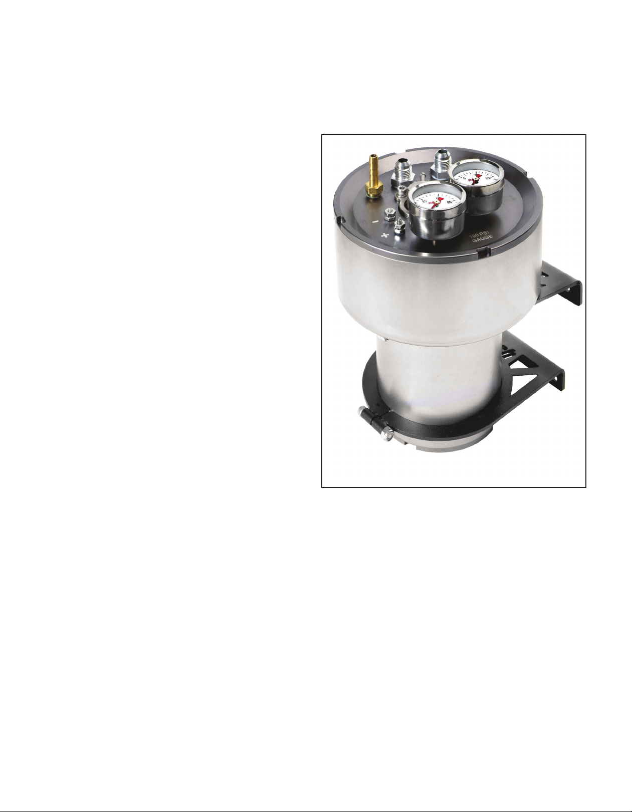
FiTech #40003 Fuel Command Center
Fuel Delivery Requirements
FiTech offers two different fuel delivery options. One is
the 40003 Fuel Command Center. When using this option,
you can configure the system to operate on a returnless
basis. The other fuel delivery system is the 40005 Frame
Mount Inline External Pump. Using this pump the system
must have a return line. The Fuel Command Center uses
your existing carbureted fuel pump and fuel lines to deliver the fuel to the Command Center which is mounted
in the engine compartment. The only plumbing required
is from the Center to the EFI.
High pressure hose and fittings are supplied with this
kit to plumb from the Command Center to the EFI throttle
body. A 340 L/PH EFI pump is submerged in the fuel in
the Command Center sump tank. The Center also has a
regulator and fuel pressure gauges.
When using the 30001/30002 Go EFI kits, the Com-
mand Center is suitable for engines making from 200 HP
to 600 HP. Either fuel delivery system can be used with
these EFI systems. When using the 8-injector 30012 Go
EFI System and the Fuel Command Center, the system is
suitable for engines making up to 800 HP. When combining the 30012 Go EFI System with the 40005 Inline
Pump, it is suitable for engines up to 600 HP.
Note: If you have elected to use the Fuel Command
Center and your vehicle currently has a high pressure fuel
injection pump, it must be replaced with a low pressure
carbureted style pump. Note that vehicles equipped with
factory high pressure EFI pumps are not compatible with
the Fuel Command Center.
If you choose to use some other fuel delivery system
other than FiTech, it is important to make sure that you
confirm its compatibility with the FiTech EFI system. Contact the FiTech technical staff to check compatibility. Failure to do so can void your warranty.
2
Page 3
Note the following special instructions:
• We recommend using the Fuel Command Center for all installations. A submerged pump is quieter and lasts longer.
• If using the Frame Mount Inline Fuel Pump, it should be mounted
s close to the fuel tank as possible and also as low as possible. It
a
should be within two to three feet of the tank. This type of pump is
designed to pump, not draw, and works best when gravity fed.
• Only use hard fuel lines when using proper EFI rated flared fittings.
Make sure that you remove ALL low pressure flex joints on factory
fuel lines and replace them with EFI rated fuel hose and use proper
flared connections and clamps. Be careful not to mix 45° and 37°
AN fittings , they look similar but will not work together. 45° fittings
usually come from a hardware store or auto parts store while 37°
AN fittings are the ones supplied by Fitech and most speed shops.
Remember that your system will be running at 58 PSI so consult a
rofessional if you are not certain about this portion of your instal-
p
lation. Fitech does not recommend aluminum fuel lines EVER! Or
ou can use the supplied EFI high pressure fuel hose that is supplied
y
in your Fuel Delivery Kit.
• Use the supplied push lock style hose ends only with the supplied
hose and vice versa. Intechanging hose ends and hose with other
rands could cause leaks.
b
VERY IMPORTANT NOTE: Your fuel tank must have a vent to prevent
pressure building up inside the tank.
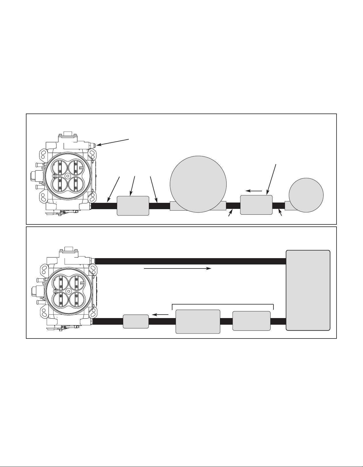
Plumbing Schematic for Fuel Command Center - Fuel Delivery Kit #40003
See separate Instruction Sheets that were provided witih this pump kit for complete details
Cap off Return Port
A carb style pre-filter is required to keep
Supplied EFI Grade Fuel Hose
plus push-lock style hose
ends, a fuel filter and fittings.
Fuel
Command
Center
Fuel Filter
debris from sticking the needle and seat
that is installed in the Command Center.
This replaces Stock Fuel Line
Plumbing Schematic for External Inline Pump - Fuel Delivery Kit #40005
See separate Instruction Sheets that were provided with this pump kit for complete details
Return fuel Line to tank
IN
3-8 PSI
Fuel Filter
Figure 1
Stock
Fuel
Pump
Figure 2
Must be mounted as low as the lowest point
IN
Post-Filter
Note:
Before starting any installation, disconnect the
ground connection on the battery. Be very careful when
disconnecting any fuel lines to let the fuel drain into a re-
Oxygen Sensor Installation
The supplied O2Sensor can be installed in either exhaust
bank. The Sensor cable connects to one of the cables
coming out of the ECU on the throttle body.
A. The ideal location for the Sensor is 2-4 inches after the
exhaust collector. It must always be at least 18-inches
from the exhaust tip. Where short or open headers are
utilized, install the sensor in the primary tube of the rear
Fuel Tank
of the Fuel Tank and within 2-feet of it
Fuel Pump
Pre-Fuel Filter
ceptacle or a dry cloth. Do not allow raw fuel to collect
on the engine as this is a fire hazard. Please observe extreme caution when working with the fuel system.
cylinder. Must be at least 8-inches from the exhaust port.
It will not work on "zoomie" style headers.
B.The sensor should be at least 10° above horizontal (see
figure #3) to allow condensation to run off. If this is not
adhered to, the sensor is susceptible to water damage.
C. Never position the sensor on the outside of a bend in
the tubing.
3
Page 4

D. The sensor must always be mounted ahead of any catalytic converter if so equipped.
E. Drill a 7/8" diameter hole in the desired location.
F. The supplied bung kit can either be welded in place or
clamped onto the pipe. The clamp-on style works well
and will not leak. If welded, make sure the bung is welded
completely all the way around and does not leak.
G. Install the sensor into the bung. WARNING: Do not
start the engine wiithout the sensor cable connected to
the throttle body and the EFI system is fully operational
or damage will occur to the sensor.
AIR LEAKS: It is important that no air leaks exist anywhere in the exhaust system between the sensor and the
engine. Any exhaust leaks will cause the unit to receive
Throttle Body Installation
Installing the throttle body is no different than replacing
the carburetor. Disconnect the throttle linkage and the
fuel line. Remove the existing carburetor from the intake
manifold. Clean the gasket surface of the manifold.
Vacuum Ports: Before installing the throttle body determine the engine's need for vacuum accessories. The
FiTech throttle body has five vacuum ports including
ported and manifold. These ports cover accessories such
as power brakes. There are three 3/16" male nipples and
two 3/8" male nipple. If you need more vacuum connections than this, you can purchase vacuum tees and vacuum hose at your local auto parts store. See Figures 4,
and 5 for location and use of various vacuum nipples.
Throttle Body Installation: Place the supplied gasket
onto the manifold and place the throttle body onto the
gasket. The throttle body linkage must be on the driver's
side of the engine. Install the original nuts and washers
onto the four carburetor studs. Tighten to 16 lb. ft. of
torque.
The FiTech throttle body has four fuel ports. Three inlet
and one return. Any one of three can be the inlet. The out-
let port is marked with the word "Return." On a returnless
setup the outlet port is plugged. Three plugs are provided
in the kit for the unused ports. Two plugs are installed in
the throttle body with one loose one in the kit. All three
plugs will be used on returnless configurations and only
two wil be used when the system will have a return line.
false readings. This
will lead to poor engine
performance, includ-
O2Sensor
Minimum
of 10°
ing misfires, and the
inability to properly
auto-tune the EFI. Continued running of the
system with an ex-
Exhaust
Collector
Figure 3
haust leak can create detonation and possible severe engine damage. Incorrect installation of the sensor, exhaust
leaks, and any resulting damage is not covered by the
FiTech manufacturer's warranty. Make sure your exhaust
is leak-free. This is very important.
Use this 3/8" nipple
for brake booster.
Use this 3/16" nipple for any
un-ported vacuum need, such
as transmission modulator.
Figure 4
Use this 3/16" nipple for ported
vacuum. (Distributor Advance)
Use this 3/8" nipple
for PCV connection.
A
Figure 5
Coolant Temperature Sensor Installation
The Temperature Sensor should be threaded into one of
the ports in the intake manifold or cylinder head. The sensor threads are 3/8-NPT. Some manifolds have 1/2-NPT
ports and in this instance use supplied pipe reducer. Con-
nect the Yellow/Black wire lead from the throttle body to
the sensor. Snap the connector into the sensor. Use
Teflon tape or a quality pipe sealant on both the pipe reducer (if used) and on the temperature sensor.
4
Page 5

Wiring the EFI System
The supplied Harness "A" (see Figure 7) plugs into mating Connector "B" from the throttle body mounted ECU.
See Figure 8. The various wires will need to be extended
to make required connections. See the Wire Chart on
page 6 which lists each wire used in the system and what
it connects to. It is strongly suggested that any wire extensions are made with the same gauge and color wire
as is used in the
supplied Harness. Make connections as a
soldered joint
rather than as a
crimped connection. Utilize a
shrink wrapped
sleeve covering
all connections.
round
G
Fan 1 - Yellow Wire, or
Fan 2 - Black Wire
ee Wire Chart on Pg. 6
S
Fan Circuit
Fuse
Battery
30
6
8
5
8
elay
R
87
Fan
Ground
Ign/Acc
Circuit Fuse
G
round
Wiring Harness
"A"
6-Pin
Figure 7
Connector
Harness "A" plugs into connector "B" from throttle body
mounted ECU. See Figure 8 and page 6 Wiring Chart.
Connects to O
Sensor Cable
Connects to Coolant
Temperature Sensor
Yellow/Black Wires
2
Handheld Controller
connections
Figure 8
The above photo shows all of the cables that are associated with the FiTech Go EFI System throttle body. The
large cable at the bottom left connects to the supplied
6-Pin Connector "B"
connects to Harness "A"
shown in Figure 7
Harness "A" which contains the main six wires used in
the system. The large coiled cable at top left connects to
the supplied Oxygen Sensor cable.
5
Page 6

Wiring Chart
The Chart below lists all of the wires in the FiTech Go EFI
System. The wires are color coded and the wires that are
part of Harness "A" are all marked for where they go.
There are six wires in Harness "A." Four of them are required connections and two are optional. More detailed
connection information (Figures 9 through 11) is provided on later pages of these instructions.
The Following Wires Are Used In All Systems (6-Pin Connecctor)
Req./Opt. Wire Color Description
Required Red (Large) Main power. Connect this wire directly to the positive (+) terminal of the battery. This circuit
needs to be live even when the switch is off so that the self learning files are maintained. This is
fused with a 25 amp fuse.
Required Yellow/Black This wire connects to the Engine Coolant Temperature Sensor
Required Blue This is the tach input wire which triggers the system. It connects to the 12V Negative terminal of
the coil. On HEI distributor it connects to the "Tach" terminal on the distributor cap or connects
to a tach output on a CDI box.
Optional Black The black wire can provide the following function when grounded:
1. RPM kicks up when A/C is activated.
Required Orange (Large) Fuel Pump circuit. This wire provides 12V to the fuel pump and connects to the positive (+) ter-
minal on the pump. No relay is required.
Required 0
Required Wiring Harness A This connects to Connector "B" from ECU. See Figures 7 and 8 (Page 5).
Required White On/Off - Connect this wire to a switched 12V circuit. Must be on during both "Key On" and
Optional Yellow Fan Circuit #1. This wire goes to the ground terminal of the fan relay.
Harness This cable from ECU connects to the Wide Band Oxygen Sensor harness.
2
"Cranking." DO NOT connect to the coil terminal when using an external CDI box such as an
MSD 6A or any other CD ignition.
Wiring Diagrams
On the following three
pages are various wiring
diagrams that address the
most common ignition
arrangements that will be
found. Each diagram will
show you the specifics of
how to wire your FiTech Go
EFI System for that particular ignition setup.
#40005 Frame Mount Inline Fuel Delivery Kit
6
Page 7

Handheld Controller
Sensor
Coolant Temperature
Yellow/Black Wire
Oxygen Sensor
Ready-to-Run Distributor
(-)
Coil
distributor & coil
Existing connection between switch,
Ignition Switch
(+)
Blue Wire - Connect
to Negative Coil Post
(-)
(+)
FiTech Go EFI Throttle Body
Black Wire
White Wire
Ground
6-Pin
Connector
Large Red Wire
Battery
Vehicle
Large Orange Wire
ECU on the EFI throttle body
This harness is a permanent connection to
Wiring Connections for FiTech Go EFI System with Ready-to-Run Distributor
how to connect a ready-to-run distributor. Figure 11 is for an HEI distributor.
Selecting the correct wiring schematic: Review Figures 10 through 11 and
Figure 11 is also for a system with an external CDI box.
select the schematic that suits your particular application. Figure 10 shows
Inline Fuel Pump
shown. Connections
are the same for the
Fuel Command Center
Electric Fan
Yellow Wire (Connect to fan relay ground)
Indicates a splice. It is
recommended that all
splices be made as a
soldered connection.
Figure 9
7
Page 8

Handheld Controller
Sensor
Coolant Temperature
Yellow/Black Wire
Oxygen Sensor
HEI Distributor
Blue
Wire to "Tach"
Connect Green
terminal on cap
Blue Wire
Ignition Switch
(-)
(+)
FiTech Go EFI Throttle Body
Black Wire
White Wire
Ground
6-Pin
Connector
Large Red Wire
Battery
Vehicle
Large Orange Wire
ECU on the EFI throttle body
This harness is a permanent connection to
Wiring Connections for FiTech Go EFI System with HEI Distributor
Inline Fuel Pump
shown. Connections
are the same for the
Fuel Command Center
Yellow Wire (Connect to fan relay ground)
Indicates a splice. It is
recommended that all
splices be made as a
soldered connection.
Electric Fan
Figure 10
Use this wiring schematic if you are utilzing an HEI distributor without an
external CDI box, such as a MSD 6AL or similar aftermarket ignition box.
8
Page 9

Distributor
Sensor
Conventional Two-Wire
Coolant Temperature
Throttle Body
FiTech Go EFI
Yellow/Black Wire
Handheld Controller
Oxygen Sensor
similar aftermarket ignition box
Coil
External CDI Box such as an MSD 6Al or
from CDI Box
to "tach out" wire
Blur Wire connects
Switch
Ignition
(-)
(+)
White Wire
Ground
Black Wire
ECU on the EFI throttle body
This harness is a permanent connection to
6-Pin
Connector
Large Red Wire
Battery
Vehicle
Large Orange Wire
Wiring Connections for FiTech Go EFI System with External CDI Box
Inline Fuel Pump
shown. Connections
are the same for the
Fuel Command Center
Yellow Wire (Connect to fan relay ground)
Indicates a splice. It is
recommended that all
splices be made as a
Electric Fan
soldered connection.
Figure 11
with an external CDI box, such as a MSD 6AL or similar aftermarket ignition box.
Use this wiring schematic if you are utilzing a conventional two-wire distributor
9
 Loading...