

INSTRUCTION MANUAL #40015 - FiTech
FiTech
Fuel Injection
®
Hy-Fuel Tight-Fit In-Tank Retrofit Kit
NOTE: This Hy-Fuel In-Tank Kit can be used with any EFI system, or with the proper low
pressure bypass style external regulator, it can also be used in carbureted installations.
Warning: Caution must be observed when installing any product
involving fuel system parts or gas tank modifications. Work in a
well ventilated area with an approved fire extinguisher readily available. Eye protection and other safety apparel should be worn to
protect against debris and sprayed gasoline. We recommend having this installation performed by an experienced, qualified, and
FiTech approved automotive technician. The finished installation
must be thoroughly checked for any fuel system leaks. The fuel
system is under pressure, so be sure to relieve the pressure before
opening the fuel system. All safety precautions must be observed
when working with fuel.
This quick start manual is designed to get you up and running with
your Hy-Fuel Tight-Fit In-Tank Retrofit Kit. The FiTech Hy-Fuel Tight-Fit
In-Tank Retro-fit Kit is the industry's most innovative fuel delivery
system.
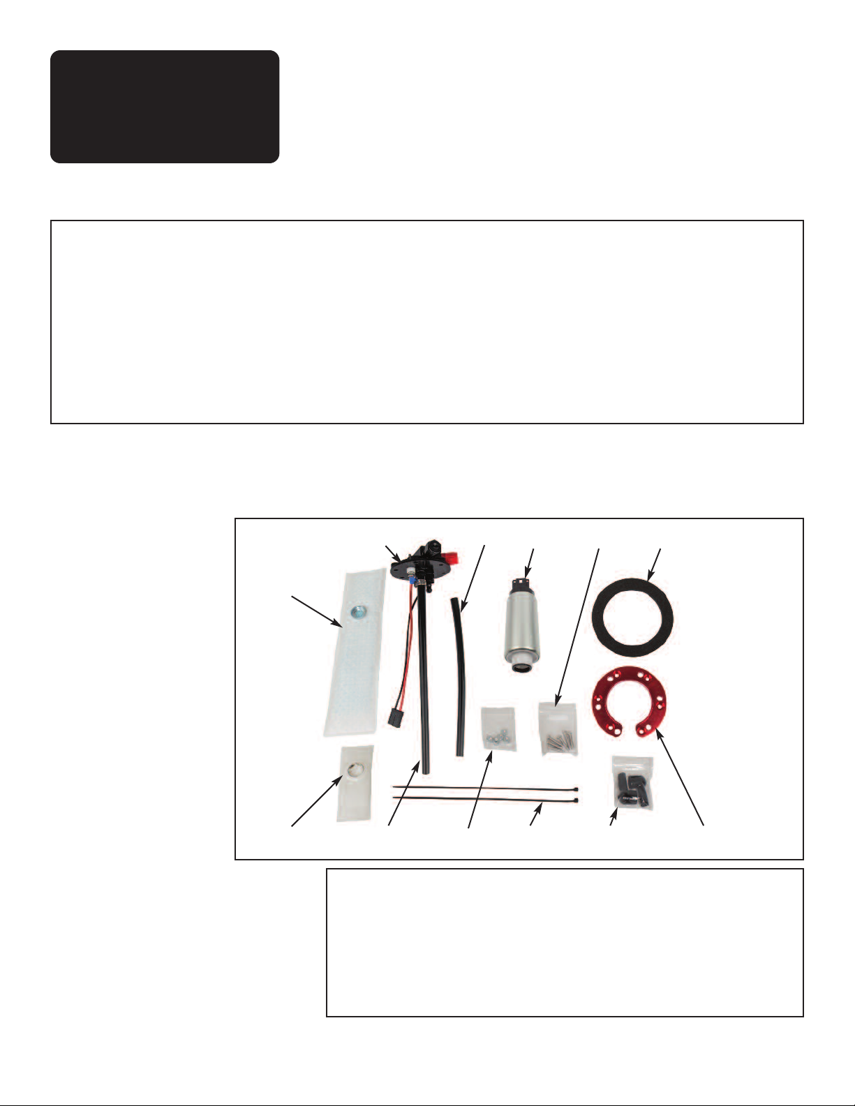
#40015 Kit Contents
1. Pump Main Assembly
2. Return Hose
3. C-Ring (Red)
4. Foam Gasket
5. 255 LPH Fuel Pump
6. (6) M5-0.8 x 25 MM Flat Head
Machine Screws
7. (6) M5-0.8 Keps Nuts
8. Outlet Hose*
9. (2) Tie Wraps
10. (2) Electrical Connections,
Nuts, Washers and Rubber Boots
11. Filter Sock (Version #1)
12. Filter Sock (Version #2)
Figure 1
11.
1.
Caution: Before starting this installation be sure the negative terminal is disconnected from the battery, you have proper eye protection, a fire extinguisher handy, and that you are working with a
clean and free of combustible fumes fuel tank. The installation of
fuel related components should be done in a well ventilated area
free of any possible fire hazards. Gasoline fumes are toxic and
highly flammable. Drilling and grinding can be a potential ignition
source. Smoking is prohibited and extinguish any open flames.
Start with a new fuel tank or have the fuel tank professionally
cleaned for the safest install. Failure to comply with the these warnings could result in injury or death.
Please read the full instruction manual before beginning your
installation. For tech-nical assistance with your Hy-Fuel In-Tank
Retrofit Kit, call 951-340-2624 or go online to www.fitechefi.com
under “tech center”.
2.
5.
6. 4.
*Note - Pump comes with Outlet
hose already assembled to fitting.
Unpack the #40015 Hy-Fuel Kit
Carefully unpack the components of your
#40015 Hy-Fuel Kit. Lay the components out on
a table and compare to Figure #1 above and the
parts list and confirm that you have all the parts.
Take the (#4) Foam Gasket and punch out all of
the holes. The holes are aready die cut but must
be punched out with a small Phillips screwdriver
or dowel rod.
8.
7.12.
RECOMMENDED TOOLS
• Slow speed Drill Motor
• 2-1/8" diameter hole saw
• Round fine file
• Shop vacuum
1
9.
10.
3.
• Screwdriver: Phillips
• Screwdriver: Small Straight Blade
• 3/8" Socket and 1/4" Drive ratchet
• 5/16" Diameter Drill Bit (Optional)
Instruction Contents:
Kit Contents 1
Recommended Tools 1
Special Instructions 2
Features 2
Drilling The Hole 2
Installing Red C-Ring 3
Black & Red Ring Installation 3, 4
Assembling the Pump 4
Installing the Pump Assembly 4
Running a Return 5
Assembly Illustrations 5
Plumbing Schematics 5, 6
Fuel Pressure Regulator 6
Warranty 6
Features
Special Instructions:
• For extended fuel pump life never let car go below 1/8th tank of gas.
• If using hard fuel lines make sure to use high pressure EFI rated lines and flared fittings.
• Make sure that you remove ALL low pressure flex joints on factory fuel lines and replace
them with EFI rated fuel hose and use proper flared connections and clamps. Be careful not
to mix 45° SAE fitting and 37° AN fittings, they look similar but will not work together. 45°
SAE fittings usually come from a hardware store or auto parts store while 37° AN fittings
are the ones supplied by FiTech and most speed shops.
• If using a return line use at least a 3/8" line.
• FiTech does not recommend aluminum fuel lines EVER! Use EFI high pressure fuel hose
on any plumbing in your system where high pressure is present.
• If using Push-Lok style hose and fittings in your fuel system, make sure all parts come
from the same manufacturer Mixing brands of hose ends and hose could cause leaks.
•FiTech's Go EFI systems are designed for unleaded pump gas up to 15% ethanol content.
• Relieve the pressure from within the system before opening the fuel system.
Very important note: Your fuel tank must have a vent or use a vented cap to prevent
pressure building up inside the tank!
The Hy-Fuel In-Tank Retrofit Kit is designed for almost any fuel
tank depending on depth. By mounting the fuel pump in the
appropriate position on the return tube, it can be installed in
tanks ranging from 6 to 12 inches in depth. Note that these instructions and this kit address installtion in stock fuel tanks
(Version #1) as well as Tanks Inc. fuel tanks (Version #2). The
FiTech Hy-Fuel low profile design allows for maximum clear-
Version #1 (Stock Tank)
Caution: Wear eye protection and ensure tank is free of combustible fumes!! Have a radiator shop boil out the tank.
Drilling the hole:
1. The HyFuel assembly must be installed into the fuel tank.
2. Before beginning to cut the 2-1/8" diameter hole, align the red CRing (#3) in a central position on the fuel tank positioned far enough
from edge of tank for clearance for the filter sock (#11). Try to find
a flat area of the tank to make the 2-1/8"" diameter hole. If this is not
possible due to ribs in the tank, the supplied thick foam gasket will
allow installation over ribbed areas.
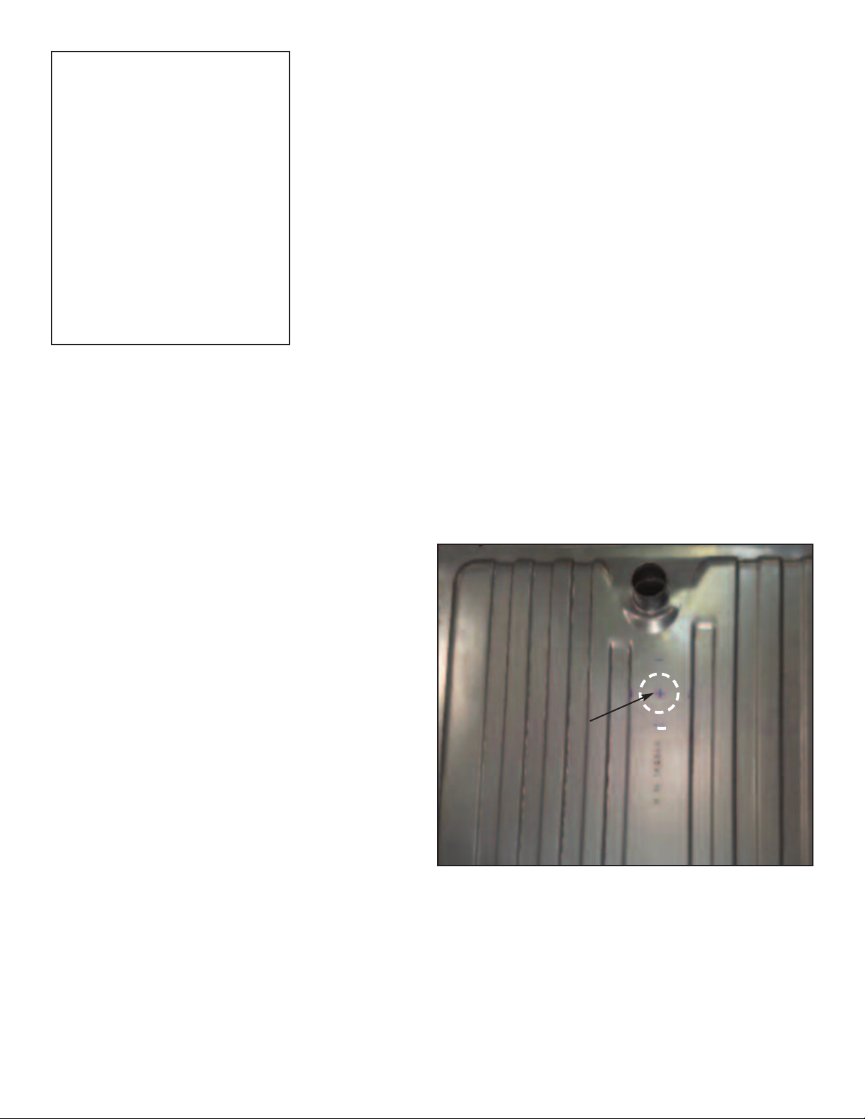
3. In selecting your hole location, be sure to avoid the stock fuel level
sending unit assembly and stock fuel pump pickup. See Figure 1.
4. With the red ring in position, mark a spot in the center of the ring.
Using a scribe, you can scribe a circle around the outside of the red
ring and then measure from the scribed line to find the center.
5. Now, you are ready to begin your cut, drill a 1⁄4" pilot hole in the
center of the X spot. See Figure #2.
ance from the floorpan of the vehicle. The system comes with
a high quality 255 LPH fuel pump for engines producing up to
600 HP naturally aspirated. It also comes with a 35 square
inch OEM style sock filter (Version #1) to ensure clean fuel,
extended fuel pump life, and a steady pickup to the pump. If
necessary, replacement parts are available from:
www.FiTechEFI.com
X
Drill 1/4"
hole
Fig. #1
6. Then using a slow speed drill with a 2-1/8" hole saw, cut a hole
in the tank. See Figure #3.
Caution edges will be sharp once hole is cut through the fuel
tank.
7. Remove the cut piece and use a file to deburr the sharp edges.
Installing the Red C-Ring
1. Using the Red C-Ring as a template, drill (6) 1/4" holes in the tank.
See Figure #4. Deburr the holes.
2. Thoroughly clean the tank to remove all of the metal chips and
debris inside and outside of the tank. Prior to final installation, it is
important that the inside of the tank is totally clean.
2

Opening for
sending unit.
Fig. #3
3. Screw the M5 Flat Head screws into the Red C-Ring and tighten.
4. Slide the Red C-Ring into the 2-1/8" diameter hole (see Figure #5)
inserting the screws back up through the (6) drilled holes. Then install the Foam Gasket (Item #4) as shown in Figure #6. See Figure
#16 on page 5 for proper assembly of these parts.
5. Snap the Filter Sock (Item #11) onto the end of the Fuel Pump.
6. Measure depth of tank and determine where pump needs to be
positioned vertically. Once you have determined proper pump location so that filter sock will be within an 1/8" of the bottom of the tank
when installed, cut a length of Hose (Item #8) to the desired length.
Using a heat gun, heat the end of the hose that will go onto the fuel
pump. (Figure #7). Push the heated hose onto the outlet nipple of
the pump. (Figure #8) Secure with a hose clamp. Then push the other
end onto the barbed Push-Lok fitting in the center of the main assembly. (Item #1) (Figure #9) There is no need to heat the other end
of the hose. Secure the hose onto the Push-Lok fitting with a hose
clamp.
7. Determine the correct length of the return hose. (Item #2) It should
be long enough to be about 1/8" to 1/4" off the bottom of the tank.
Then push the hose onto the barbed Push-Lok return fitting (marked
"A" in Figure #12). Secure with a hose clamp.
7. Then locate the pump against the Return Hose (Item #2) and secure into position with two Tie Wraps (Items #9). Make sure Tie
Wraps are pulled tight. See Figure #10. Plug the electrical connector
onto the Fuel Pump.
8. Insert Pump Assembly into tank. Lower down over extended M5
machine screws. See Figure #6 and Figure #11.
9. Thread the (6) Nuts (Item #7) onto the exposed bolts and tighten
securely using a criss-cross pattern to tighten them down evenly.
Fig. #4
Fig. #5
Fig. #6
Foam
Gasket
Fig. #7
Fig. #8
Fig. #9
3

Fig. #10 Fig. #11
Secure Pump to
Return Tube with
(2) Tie Wraps.
Second tie wrap
is obscured by
technicans hand.
Make sure tie
wraps are tight.
This Photo is
similar for both
Versions 1 & 2.
Carefully feed filter sock
and the pump assembly
into the fuel tank opening.
Figure 12
Version #2 (Tanks Inc. Fuel Tank)
Installing the Pump Unit
Because you are installing the FiTech Mini In-Tank Fuel Pump Assembly into a fuel tank that already has an access hole and tapped
holes to thread into (see Figure 13), no cutting or drilling is required.
1. Snap the Filter Sock (Item #12) onto the end of the Fuel Pump.
2. Measure depth of tank and determine where pump needs to be
positioned vertically. Once you have determined proper pump location so that filter sock will be within an 1/8" of the bottom of the tank
when installed, cut a length of Hose (Item #8) to the desired length.
Using a heat gun, heat the end of the hose that will go onto the fuel
pump. (Figure #7). Push the heated hose onto the outlet nipple of
the pump. (Figure #8) Secure with a hose clamp. Then push the
other end onto the barbed Push-Lok fitting in the center of the main
assembly. (Item #1) (Figure #9) There is no need to heat the other
end of the hose. Secure the hose onto the Push-Lok fitting with a
hose clamp.
3. Determine the correct length of the return hose. (Item #2) It
should be long enough to be about 1/8" to 1/4" off the bottom of the
tank. Then push the hose onto the barbed Push-Lok return fitting
(marked "A" in Figure #12). Secure with a hose clamp.
4. Then locate the pump against the Return Hose (Item #2) and secure into position with two Tie Wraps (Items #9). Make sure Tie
Wraps are pulled tight. See Figure #10. Plug the electrical connector
onto the Fuel Pump.
4. Place the Foam Gasket (Item #4) over the (6) holes in the Tanks
Inc. fuel tank. Align the holes. See Figure #10.
8. Insert Pump Assembly into tank. See Figure #11. Align holes in
the black top cap of the Main Assembly (Item #1) with the holes in
the gasket and tank. Thread the (6) Machine Screws (Item #6)
through the Main Assembly and the gasket and into the threaded
holes in the tank. Tighten securely using a criss cross pattern to assure they are tightened evenly.
Connects to
Fuel Pump
Outlet Hose #8
Connects to
Fuel Pump
A = Return Hose Fitting
B = Vent Port
+
AB
4

Opening for
sending unit.
The FiTech Mini
n-Tank Retrofit
I
Kit bolts directly
to this opening
on a Tanks Inc.
fuel tank.
Figure 14
Figure 13
Installing the Fuel Tank back in Vehicle
1. Install the fuel tank into the vehicle and attach the fuel lines.
2. Attach the fuel pump power wire to the positive terminal and cover the terminal with the provided insulation boot. See Figure #19.
3. Next attach one side of a ground wire to the negative terminal and the other
end to a good ground on the chassis. See Figure #19. Make sure the positive
terminal has clearance and/or insulation to avoid the possibility of hitting the
bottom of the car floorpan. One option is to lay a piece of foam over the top
of the pump to insure the pump will not short out against any metal. The foam
can be purchased from any home improvement store.
4. Run a return line from the return fitting on the throttle body to the return
port on the Hy-Fuel unit if applicable. See Figure #18.
See below for more complete information on plumbing the system.
5. Make sure there is gas in the tank.
6. Reconnect your battery.
7. Turn your key to the "On" position, don't crank.
8. Thoroughly check for any leaks.
9. If no leaks are present then you are ready to start your vehicle.
Plumbing for a Return Style System
The Hy-Fuel In-tank Retrofit Kit must be run with
a return fuel line. Note that the center red -6 ORB
fitting (marked P) is always the pressure out port.
The Port marked "B" in Figure 12 is always the Vent
Port and the Port marked "A" in Figure 12 is always
the Return Port. Do not attempt to use the Vent
port for the Return line. If the fuel tank is not
vented, use the "B" port as a vent. See Figure #18
for plumbing a Return style.
When using a Go Street or Mean Street EFI system, these systems contain an internal fuel pressure regulator inside the throttle body. If you are
using this Hy-Fuel Mini In-Tank Retrofit Fuel Pump
with any other EFI system, an external fuel pressure regulator will be required as the supplied
pump in the Hy-Fuel system exceeds 60 PSI. In a
case where the pump and fuel tank are mounted
inside the car, we recommend routing a vent hose
from the vent port on the FiTech Hy-Fuel Kit routed
to the outside of the vehicle.
Wiring the 40015 Kit
See the Wiring Schematic (Figure #19) on the next
page (Page 6). Use recommended wire sizes.
Nut #7
Thread (6) M5 flat head machine
screws, (Item #6) and tighten into Red
Ring before assembly. Use Loctite Red
sealer on these (6) screws.
(6) Flat Head Machine Screws
(Item #6)*
Figure 15
Sock (Item #12)
Figure #16
Version #1
Installation
Pump Assy #1
Foam Gasket #4
Fuel Tank
Red Ring #3
Figure #17
Version #2
Installation
Pump Assy #1
Foam Gasket #4
Tanks Inc. Fuel Tank
Pre-assembled nuts in
Tanks Inc. Fuel Tank
5
*It is recommended to use Loctite Thread
Sealer (Blue) on these (6) screws.

Figure #18
With Return Line
R
Pressure Out Port
R
ed Fitting is
Vent
If Req'd
V
FiTech Throttle Body
ost Filter
P
Connect to any one of
three inlet ports
Return
FiTech Hy-Fuel Mini In-Tank Fuel
Pump Main Assembly
A suitable external Fuel Pressure Regulator will
be required for any EFI system that does not include a built-in regulator. FiTech EFI Throttle
Bodies include a regulator.
To Retun Port on
Pump Assembly
Notes:
1. Mount fuse close to power source.
2. Mount relay close to pump.
3. If a mechanical feeder pump is used, connect ECU
orange wire directly to Relay Terminal 86.
4. Relay shown is typical of Bosch 12V/40A SPSP Relay.
Figure #19
Aternatively connect to a Fuel Rail
Fuel Rail on a Port Injection System
Fuel Pressure Regulator
Fuel Rail on a Port Injection System
GROUND
14GA
Wiring Schematic for 40015 FiTEch Hy-Fuel Mini Retrofit Fuel Pump
Limited Warranty: FiTech EFI warranty is limited to repair or replacement (at our discretion)
of any FiTech part that fails because of a defect in workmanship or materials.
Implied warranty: Any warranties implied by law are limited to the duration of this warranty
(except in those states where prohibited by law).
How Long It Is Covered: All FiTech products are warranted for a period of one year from date
of original retail purchase with an original receipt showing proof of purchase.Certain compo-
nents of the EFI systems are limited to a 90 day warranty period. See separate complete Lim-
ited Warranty document for a list of specific components.
Who We Cover: All FiTech warranties apply to the original purchasing consumer.
What We Do Not Cover: Failure of a product due to misapplication, improper installation or
maintenance, misuse, abuse, unauthorized repairs, accidents, or modifications to the original
design. Removal or replacement costs, shipping costs, damage to related components, and
costs incurred due to downtime of vehicle. Any product used in marine applications unless
specifically stated for marine usage. Any parts used in racing applications or subject to ex-
cessive wear.
Warranty Service Procedure: In the event a problem develops with one of our products, con-
tact our customer service department at 951-340-2624 or fax to 951-340-2648. It may be
California Proposition 65 Warning: This product may contain one or more substances or
chemicals known to the state of California to cause cancer, birth de- fects, or other reproductive
harm.
LIMITED WARRANTY
FiTech EFI • 12370 Doherty Street • Suite A • Riverside, CA 92503
Phone: 951-340-2624 • Email: sales@FiTechEFI.com • Website:www.FiTechEFI.com
determined that the product will have to be returned for in- spection and/or repair. A Return
Merchandise Authorization (RMA) number will be assigned to you. This number must be on
the box shipped back to FiTech Customer Service . The product must be returned via freight
prepaid. It must be ac- companied by a clear description of what the problem is with the product. If the product is determined to be defective within the warranty period, FiTech will repair,
replace, or issue credit to the original consumer at our discretion. Any re- paired or replaced
product will be returned to the sender via prepaid Fedex or other ground carrier.
Return Policy: FiTech guarantees its parts and is confident that our products will meet with
your complete satisfaction. If the product does not meet your expectations, return it within
60 days for a refund or exchange. You can return the new, unused part within 60 days from
the purchase date. To make a return, call our Customer Service Dept. at 951-340-2624 to receive a Return Merchandise Authorization (RMA) number. You must include the RMA number
and a copy of the product purchase receipt with the return. The product must be sent back
freight prepaid, in the original manufacturer’s box to FiTech Customer Service/ 12370 Doherty
St. Suite A, Riverside, CA 92503 . Returns may be subject to a 15% restocking fee. No refunds
will be issued without a copy of the receipt.
6
40015 Instructions - 10-9-17
 Loading...