

Page 1
ProScanner Setup Guide
This guide will walk you through the steps to get
your Fit3D ProScanner up and running.
QUESTIONS?
?
1
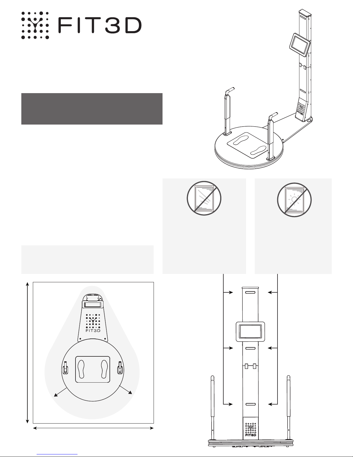
For the best scan quality, please ensure the
environment for ProScanner is appropriate.
The three most important factors are:
• Adequate spacing;
• No reflective surfaces;
• No natural sunlight.
Please see notes below for more info.
Adequate space is CRITICAL for scan
processing and accurate data. A clear
area 62 x 78 in (157 x 198 cm) is required.
Visit our online help center at
support.fit3d.com
Select a Location
for the ProScanner
No reflective surfaces
in view of the cameras
Mirrors, glossy posters,
windows, and chrome
finishes can cause poor
quality scans and failures.
No natural sunlight in
view of the cameras
Natural sunlight can
cause poor quality
scans and failures.
M
U
S
T
K
E
78 in (198 cm)
E
P
C
L
E
A
R
at least
1-foot
(30 cm)
C
R
M
I
T
I
U
62 in
C
A
L
S
T
K
A
S
C
P
E
E
(157 cm)
E
N
O
Z
N
R
A
E
L
C
Spacing Advisory for ProScanner System
R
A
E
L
C
P
E
E
K
T
S
U
M
at least
1-foot
(30 cm)
Page 2
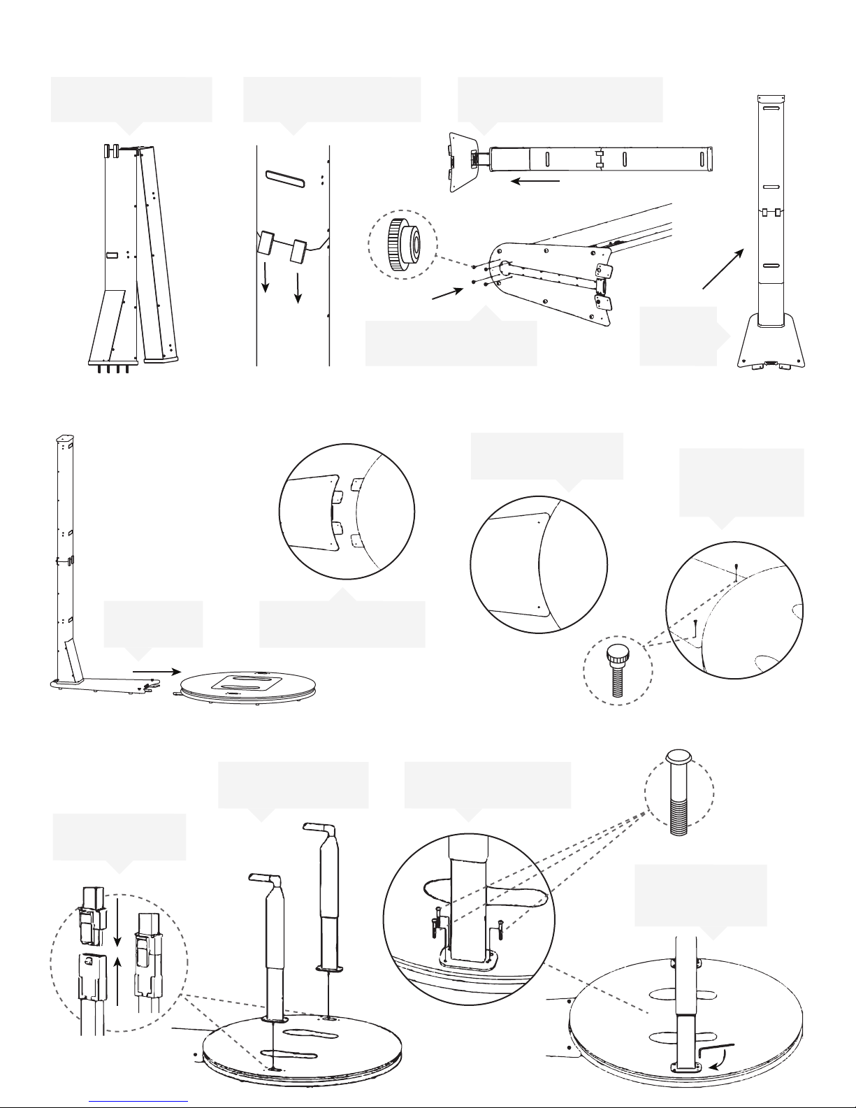
Prepare the Camera Tower Assembly
2
Unfold camera tower
1
to stand upright
3
Attach the Camera Tower to the Turntable
Hook and push both
2
latches down to secure
4
Carefully insert the camera
3
tower into the base
Attach 4 thumb nuts to
secure camera tower
Ensure connection
3
is fully engaged
Camera Tower
Carefully
5
Raise the
Tower
Attach 2 nylon
4
thumb screws
to secure
Pull tower to
1
turnable
4
Install the Handles
2
Connect handles
1
and turntable
Carefully align base
2
and turntable
After connection,
set handles upright
Use 3 metal screws to
3
secure each handle
Use Allen key
4
(included)
to tighten screws
Page 3
5
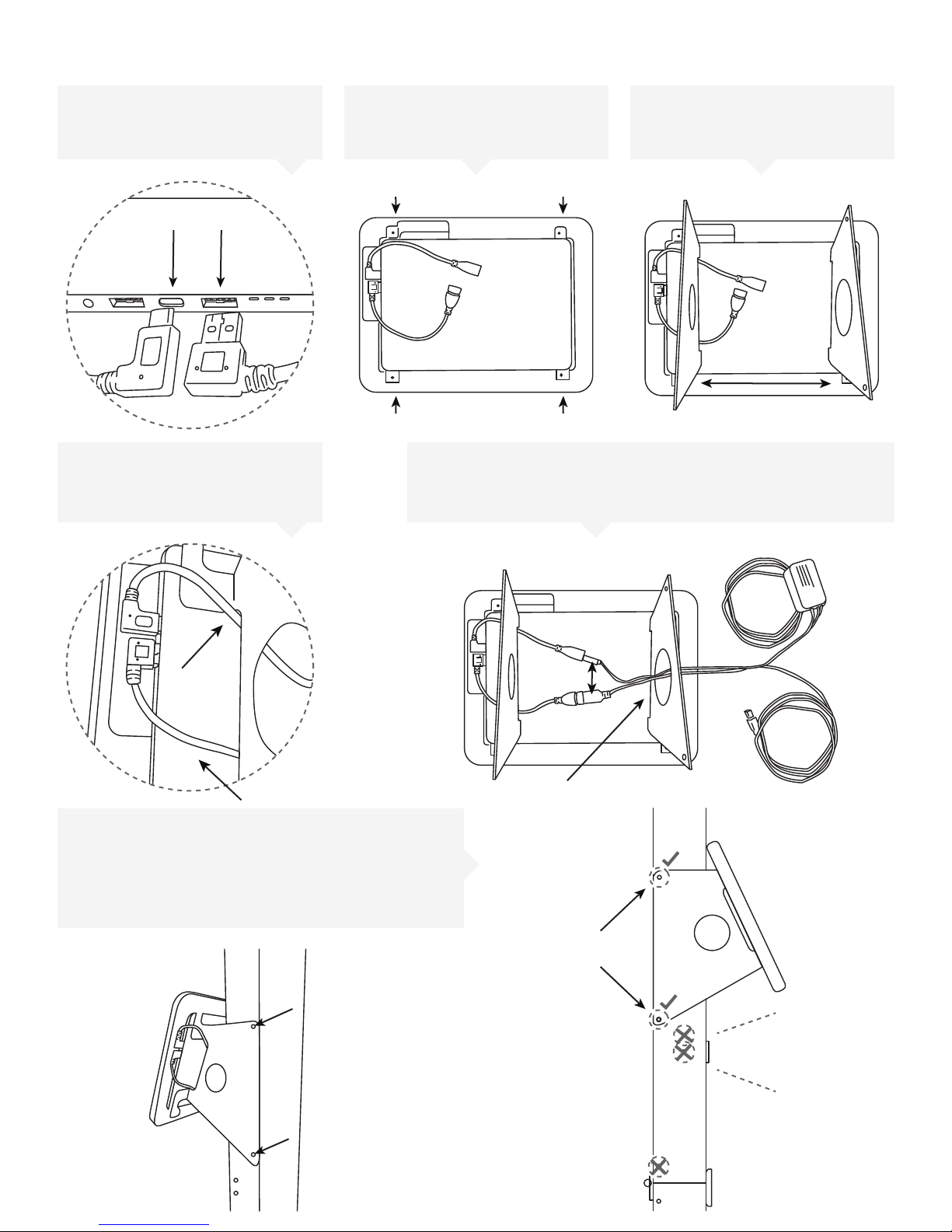
Prepare the Camera Tower Assembly
Connect the USB Type-C
1
and Type-A angle adapters
as shown
Route the cables underneath
4 5
the mounting bracket as
shown
Set the tablet into the bezel
2
Attach the left and right
3
mounting brackets to the bezel
with four of the included screws
Connect the tablet power supply and the USB cable to the
adapters. Route the cables through the round hole of the
mounting bracket on the right as shown
Remove the four small screws from the camera
6
tower located along the rear edge above the
center camera location. Use four of the longer
screws included with the tablet accessories to
attach the tablet assembly to the camera tower
Attach
Screws
Center
Camera
View
Page 4
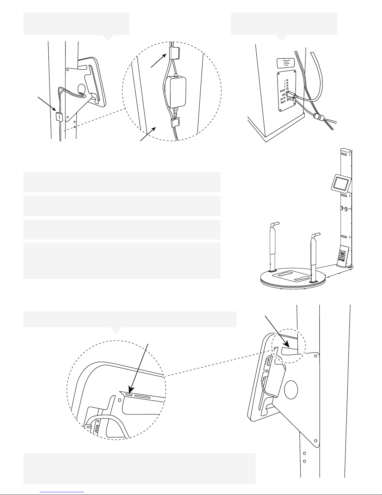
Route the tablet USB and
7
power cables using cable clips
System Power and Calibration
6
Connect the ProScanner power supply to the camera tower
control module
Connect the USB cable to the
8
camera tower
Connect the ProScanner and tablet power supplies to a
power outlet
All of the lights on the camera tower will illuminate and the
turntable will begin to rotate
When you power the ProScanner on for the first time, the
turntable will spin around once and stop facing the camera
tower. On the back panel, you should only see the blue light
for power when calibration is complete
Starting the Tablet And Application
7
Turn on the tablet by holding the power button for 5 full seconds
• Turn on the tablet by holding the power button for 5 full seconds.
• Connect to a Wi-Fi network.
• Double-tap the ProScanner application icon to start the program.
• Follow the on-screen instructions to complete system activation.
FIT26-12045 Rev. E
 Loading...