

Fisker Karma 2012, Karma Owner's Handbook Manual

Owner’s Handbook
© 2012 Fisker Automotive, Inc.
All rights reserved. Information contained in this document is based on the latest information available at the time of printing and
is subject to the copyright and other intellectual property rights of Fisker Automotive, Inc. (Fisker), its affiliated companies and its
licensors. All rights are reserved to make changes at any time without notice. No part of this document may be reproduced, stored
in a retrieval system, or transmitted in any form or by any means, electronic, mechanical, photocopying, recording, or otherwise,
nor may these materials be modified or reposted to other sites, without the prior expressed written permission of the publisher.


Table of Contents
Document Number: C1810ASD0025.03 (April 2012)
©2012 Fisker Automotive, Inc. All rights reserved.
i
1 Introduction
1.2 Introduction
1.3 Information About Your Vehicle
1.6 Consumer Information
6Power
6.2 Charging the Vehicle
6.9 Solar Roof
6.10 Fuel Filling
2Overview
2.2 Exterior
2.3 Interior
2.4 Instruments and Displays
3 Vehicle Security
3.2 Locking and Unlocking the Vehicle
3.7 Trunk
3.8 Glove Compartment and Valet Mode
4 Occupant Safety
4.2 Seats and Steering Column
4.5 Seat Belts
4.9 Child Restraints
4.13 Supplementary Restraint System
(SRS)
5 Controls and Operation
5.2 Instruments
5.6 Wipers and Washers
5.7 Exterior Lighting
5.9 Power Windows
5.10 Mirrors
5.11 Touch-screen
5.14 Climate Control
5.20 Starting and Driving
5.25 Brakes
5.28 Electronic Stability Control
5.29 Cruise Control
5.31 Exterior Sound
5.32 Parking Aids
5.34 Voice Command System
5.36 Garage Door Opener
5.38 Accessory Sockets
7 Maintenance
7.2 Maintenance Requirements
7.4 Hood
7.5 Engine Compartment
7.12 Wipers and Washers
7.13 Cleaning and Vehicle Care
7.18 Fuses
7.21 Raising the Vehicle
7.22 Vehicle Recovery
8 Wheels and Tires
8.2 Tire Care
8.8 Tire Pressure Monitoring System
(TPMS)
8.10 Tire Repair Kit
8.14 Tire Information
8.20 Glossary of Terms
9 Technical Specifications
9.2 Vehicle and Component
Identification
9.3 Vehicle Dimensions and Weights
9.5 Wheels and Tires
9.6 Subsystem Specifications
Index


1.1
Introduction
Introduction
1.2 WELCOME TO THE FISKER FAMILY
1.2 USING THIS MANUAL
1.2 SYMBOLS GLOSSARY
1.2 NOTES ABOUT THIS MANUAL
Information About Your Vehicle
1.3 ELECTRIC VEHICLE PRECAUTIONS
1.3 MAINTENANCE AND REPAIRS TO
YOUR VEHICLE
1.3 BODY REPAIRS
1.4 VEHICLE MODIFICATIONS
1.4 QUALITY CONTROL
1.4 CALIFORNIA PROPOSITION 65
1.4 CALIFORNIA PERCHLORATE
ADVISORY
1.5 DATA RECORDING
Consumer Information
1.6 IF YOU NEED ASSISTANCE
1.6 REPORTING SAFETY DEFECTS
1.2
Introduction
IntroductionIntroduction
WELCOME TO THE FISKER
FAMILY
From everyone at Fisker, thank you for
purchasing one of our vehicles.
Introduction
SYMBOLS GLOSSARY
The following symbols used within this
manual call your attention to specific types
of information.
Your Karma is designed to deliver
uncompromised responsible luxury and
performance - Pure Driving Passion.
We are committed to providing you with an
ownership experience that is second to
none, and we look forward to serving you in
the years ahead.
USING THIS MANUAL
For your own safety, follow the instructions
and warnings contained in this manual.
Ignoring them could result in damage to the
vehicle or personal injury to you or others.
Vehicle damage caused by failing to follow
instructions is not covered by the New
Vehicle Limited Warranty.
Keep this manual in your vehicle as a
reference for the safe and enjoyable use of
your vehicle. Should you resell your car,
leave this manual with it for the next owner.
If you are unable to find the information you
need, it may be contained within one of the
additional documents included in your
Owner’s literature pack:
• Quick Reference Guide - a summarized
version of this document allowing you to
quickly familiarize yourself with the
vehicle.
• Touch-screen User’s Manual - describes
how to use the features of the touchscreen.
WARNING: Indicates either an
instruction which must be followed
precisely, or information that should be
considered with great care in order to avoid
the possibility of personal injury or injury to
others.
CAUTION: Indicates either an
instruction which must be followed
precisely, or information that should be
considered with great care in order to avoid
the possibility of damage to your vehicle.
This symbol identifies instructions
that should be observed in order to
prevent unnecessary damage to the
environment.
NOTES ABOUT THIS MANUAL
All specifications and descriptions are
accurate at the time of printing. Because
improvement is a constant goal at Fisker
Automotive, we reserve the right to make
changes at any time, without notice and
without obligation.
Note: This manual applies to all Fisker
Karmas. As a result, you may find some
explanations for equipment or options not
installed on your vehicle
Copyright © 2011 Fisker Automotive, Inc.
All rights reserved.
• New Vehicle Limited Warranty and
Servicing - details of the vehicle
warranty and servicing requirements for
your vehicle.
• Tire Warranty - details the warranty for
the vehicle’s tires.
Information About Your Vehicle
1.3
Information About Your Vehicle
ELECTRIC VEHICLE
PRECAUTIONS
MAINTENANCE AND REPAIRS TO
YOUR VEHICLE
IMPORTANT
Your Fisker Karma is an electric vehicle
with a range-extending gasoline engine.
The Karma has both high-voltage DC and
AC systems as well as a 12-volt system.
Both the DC and AC high voltage systems
are very dangerous and can cause
personal injury, severe burns, electric
shock and even fatal injury unless
appropriate precautions are taken.
Always observe and obey the instructions
on labels attached to components on the
vehicle - they are there for your safety.
Do not touch, attempt to remove or
replace any high voltage parts, wiring
(identified by the orange outer sleeving) or
connectors.
If the vehicle is involved in an accident, do
not touch any high voltage wiring,
connectors or the components
connected to the wiring.
If a vehicle fire occurs, extinguish it with a
Class D powder-type fire extinguisher.
Fisker Automotive recommends having
maintenance and repairs for your Karma
performed by an authorized Fisker Retailer.
To locate your nearest authorized Fisker
Retailer, go to www.fiskerautomotive.com
or contact Fisker Consumer Affairs.
BODY REPAIRS
If you're involved in a collision, you want
your vehicle to be returned to its preaccident condition when repaired. That's
why it is important to make sure your
vehicle is repaired with only genuine Fisker
Automotive parts.
Some repair shops and insurance
companies may suggest using non original
equipment or salvaged parts to save
money. However, these parts do not meet
Fisker's high standards for quality, fit and
corrosion resistance. In addition, non
original equipment and salvaged parts (and
any damage or failures they may cause) are
not covered by any Fisker warranty.
The best way to ensure that your vehicle is
repaired with genuine Fisker Automotive
parts is to take it to a Fisker Retailer. Each
Retailer works with selected collision repair
centers that meet Fisker's strict
requirements for training, equipment,
quality, and customer satisfaction. These
repair centers use genuine Fisker
Automotive parts exclusively in the repair of
Fisker vehicles.
Information About Your Vehicle
1.4
Information About Your Vehicle
VEHICLE MODIFICATIONS
WARNING: The installation of non-
approved parts and accessories, or
the carrying out of non-approved
modifications, may be dangerous and could
affect the safety of the vehicle and
occupants and also invalidate the terms and
conditions of the vehicle warranty.
WARNING: Fisker Automotive will not
accept any liability for death, personal
injury or damage to property which may
occur as a direct result of non-approved
modifications or the installation of nonapproved accessories.
If you have a disability which may require
modification to the vehicle, please contact
Fisker Automotive before any modifications
are made.
QUALITY CONTROL
You may have noticed a few miles (kms) on
the odometer when you took delivery of
your Karma. This is a result of the
comprehensive process used to ensure the
quality of your vehicle.
CALIFORNIA PROPOSITION 65
WARNING: Certain vehicle
components contain or emit
chemicals known to the State of California
to cause cancer and birth defects or other
reproductive harm. In addition, certain fluids
contained in vehicles and certain products
of component wear contain or emit
chemicals known to the State of California
to cause cancer and birth defects or other
reproductive harm.
CALIFORNIA PERCHLORATE
ADVISORY
WARNING: Certain components of
this vehicle such as air bag modules,
seat belt pre-tensioners and Lithium
batteries may contain Perchlorate Material -
- Special handling may apply for service or
vehicle end of life disposal. See http://
www.dtsc.ca.gov/hazardouswaste/
perchlorate.
This process includes extensive
inspections during and after production.
The final inspection takes place at the
selling Retailer and includes a road test
conducted by a trained Fisker Automotive
Technician.

Information About Your Vehicle
1.5
DATA RECORDING
Service data recording
Service data recorders in your vehicle are
capable of collecting and storing diagnostic
information about your vehicle. This
potentially includes information about the
performance or status of various systems
and modules in the vehicle such as engine,
throttle, steering or brakes. In order to
properly diagnose and service your vehicle,
Fisker Automotive and service facilities may
access vehicle diagnostic information
through a direct connection to your vehicle.
Event data recording
This vehicle is equipped with an Event Data
Recorder (EDR). The main purpose of an
EDR is to record, in certain crash or near
crash-like situations, such as an air bag
deployment or hitting a road obstacle, data
that will assist in understanding how a
vehicle's systems performed. The EDR is
designed to record data related to vehicle
dynamics and safety systems for a short
period of time, typically 30 seconds or less.
Note: EDR data are recorded by your
vehicle only if a non-trivial crash situation
occurs; no data are recorded by the EDR
under normal driving conditions and no
personal data (e.g., name, gender, age, and
crash location) are recorded. However,
other parties, such as law enforcement,
could combine the EDR data with the type
of personally identifying data routinely
acquired during a crash investigation.
To read data recorded by an EDR, special
equipment is required, and access to the
vehicle or the EDR is needed. In addition to
the vehicle manufacturer, other parties,
such as law enforcement, that have the
special equipment, can read the information
if they have access to the vehicle or the
EDR.
The EDR in this vehicle is designed to
record such data as:
• How various systems in your vehicle
were operating;
• Whether or not the driver and passenger
safety belts were buckled/fastened;
• How far (if at all) the driver was
depressing the accelerator and/or brake
pedal; and,
• How fast the vehicle was traveling;
• Where the driver was positioning the
steering wheel.
These data can help provide a better
understanding of the circumstances in
which crashes and injuries occur.

1.6
Consumer Information
Consumer Information
IF YOU NEED ASSISTANCE
Consumer Information
REPORTING SAFETY DEFECTS
Both Fisker Automotive and your Fisker
Retailer are dedicated to serving your
automotive needs. Your complete
satisfaction is our first priority. Should you
have a problem or concern, please take the
following steps to ensure the quickest
possible response:
Step 1 - Discuss the situation with a
Retailer manager, such as the service
manager or customer satisfaction manager.
If necessary, ask the Retailer owner or
general manager for assistance. In most
cases, a satisfactory solution can be
reached at this step.
Step 2 - If the Retailer does not address
your concern to your satisfaction, call the
Fisker Consumer Affairs at:
1 (855) 575 7577
You may also write to us at:
Fisker Consumer Affairs Department
5515 East La Palma
Anaheim, CA 92807.
Whether calling or writing, please provide
the following information:
• 17-digit Vehicle Identification Number
(VIN) found on the vehicle registration
paperwork and on the certification label
located on the driver's door pillar
• Current vehicle odometer reading
• Name of your selling and servicing
Fisker Retailers
• Your day and evening contact telephone
numbers
• Your email address
United States
If you believe that your vehicle has a defect
which could cause a crash or could cause
injury or death, you should immediately
inform the National Highway Traffic Safety
Administration (NHTSA) in addition to
notifying Fisker Automotive.
If NHTSA receives similar complaints, it
may open an investigation, and if it finds
that a safety defect exists in a group of
vehicles, it may order a recall and remedy
campaign. However, NHTSA cannot
become involved in individual problems
between you, your dealer, or Fisker
Automotive.
To contact NHTSA, you may call the Vehicle
Safety Hotline toll-free at 1-888-327-4236
(TTY: 1-800-424-9153); go to
http://www.safercar.gov
Administrator
National Highway Traffic Safety
1200 New Jersey Avenue SE.
Washington, DC 20590.
You can also obtain other information about
motor vehicle safety from
http://www.safercar.gov
Canada
If you believe that your vehicle has a defect
which could cause a crash or could cause
injury or death, you should immediately
inform Transport Canada, in addition to
notifying Fisker Automotive.
To contact Transport Canada, call their tollfree number: 1-800-333-0510.
; or write to:
.

2.1
Overview
Exterior
2.2 EXTERIOR OVERVIEW
Interior
2.3 INTERIOR OVERVIEW
Instruments and Displays
2.4 INSTRUMENT CLUSTER
2.5 TOUCH-SCREEN
2.2
Exterior
OverviewExterior
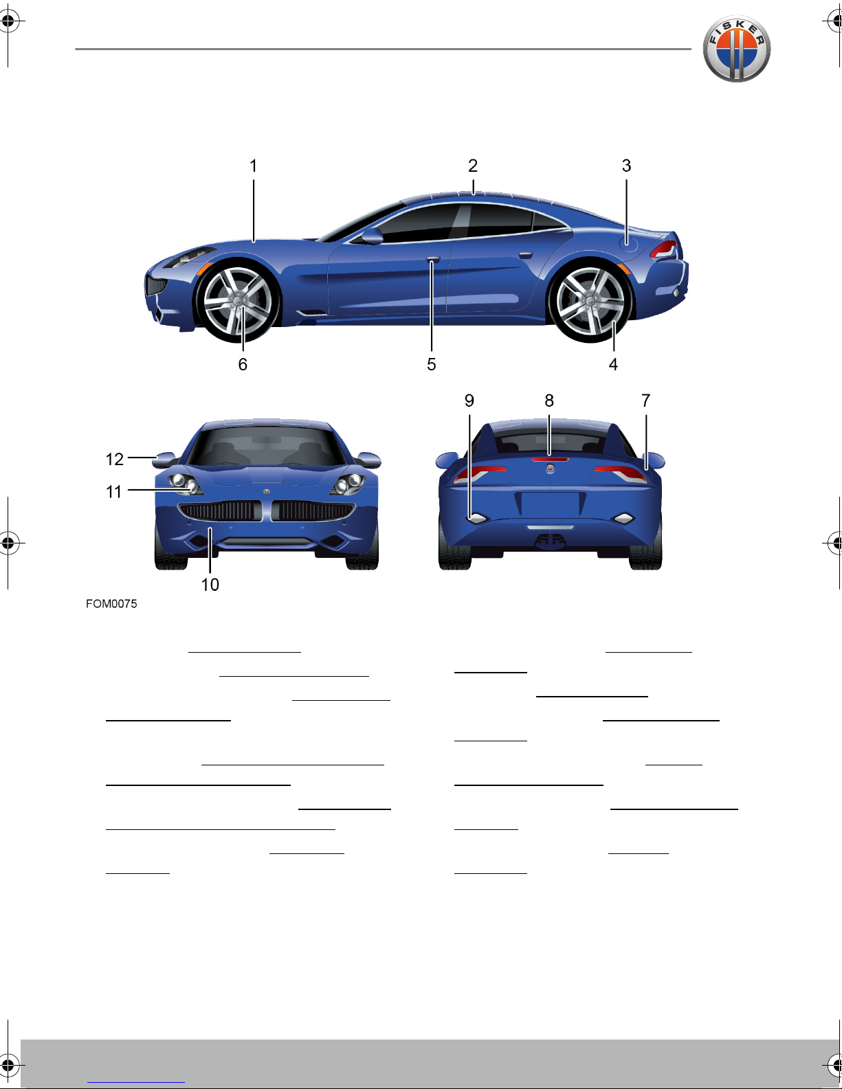
EXTERIOR OVERVIEW
Exterior
1. Hood. See Hood, page 7.4.
2. Solar roof. See Solar Roof
3. Charging port cover. See Charging the
Vehicle, page 6.2.
4. Tire Pressure Monitoring System
(TPMS). See Tire Pressure Monitoring
System (TPMS), page 8.8.
5. Exterior door release. See Locking and
Unlocking the Vehicle, page 3.2.
6. Wheels and tires. See Tire Care
page 8.2.
, page 6.9.
,
7. Fuel filler cover. See Fuel Filling
page 6.10.
8. Trunk. See Trun k
9. Exterior sound. See Exterior Sound
page 5.31.
10. Vehicle recovery eye. See Vehicle
Recovery, page 7.22.
11. Exterior lighting. See Exterior Lighting
page 5.7.
12. Exterior mirrors. See Mirrors
page 5.10.
, page 3.7.
,
,
,
,
Interior
2.3
Interior
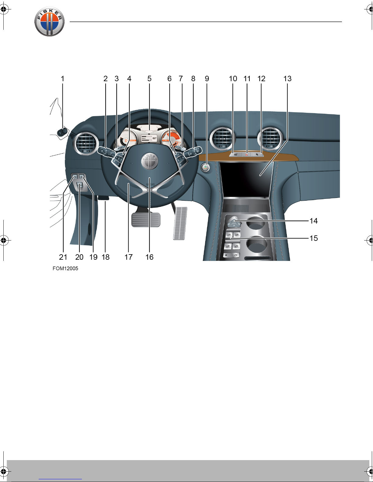
INTERIOR OVERVIEW
1. Exterior mirror control
2. Exterior lights and turn signals
3. STEALTH/SPORT mode selection
4. Audio and phone controls
5. Instrument cluster
6. Cruise control
7. HILL mode selection
8. Wipers and washers
9. Start/Stop button
10. Master door locking
11. Hazard warning flashers
12. Glove compartment open
13. Touch-screen interface
14. Mode selector
15. Power windows
16. Horn
17. Steering column adjustment
18. Hood release (recessed)
19. Fuel filler cover release.
20. Parking brake
21. Trunk release
2.4
Instruments and Displays
Instruments and Displays
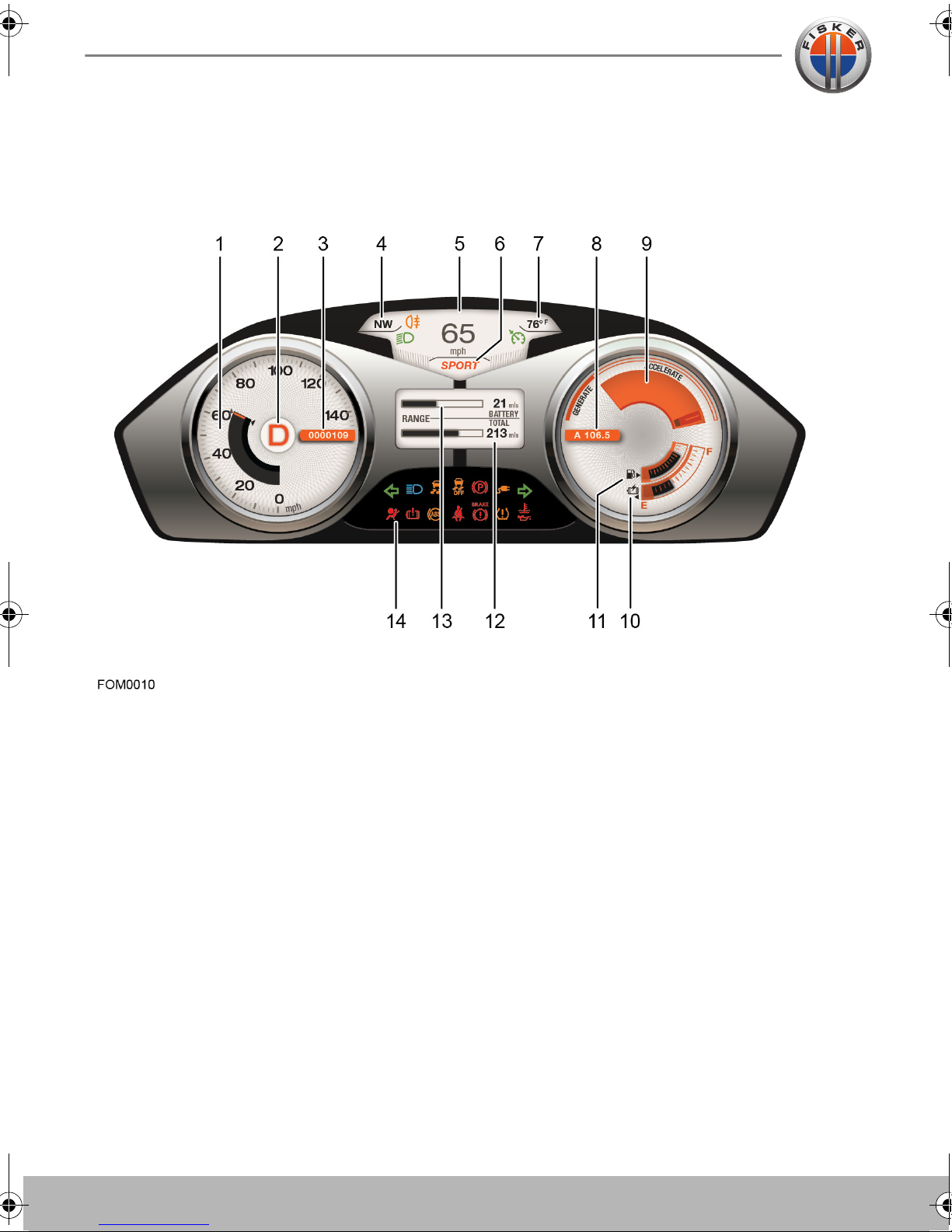
INSTRUMENT CLUSTER
Instruments and Displays
1. Speedometer
2. Mode indicator
3. Odometer
4. Compass
5. Clock/Driver information display
6. Driving mode
7. External temperature
8. Trip display
9. Power meter
10. Battery charge level indicator
11. Fuel level indicator
12. Total range
13. Battery range
14. Indicator lights

Instruments and Displays
2.5
TOUCH-SCREEN
1. Compass
2. Current operating mode
3. Secondary time zone
4. Primary time zone
5. Climate
6. Audio
7. Phone
8. Navigation
9. System
10. Volume
11. Driver’s heated seat
12. Windshield defogger
13. Rear window heater
14. Electronic Stability Control (ESC)
15. Park Distance Control (PDC)
16. Exterior mirror fold
17. Front passenger’s heated seat
Note: For detailed instructions on how to use the many features of the touch-screen, please
refer to the “Touch-screen User’s Manual” provided in the Owner’s Literature Pack.


3.1
Vehicle Security
Locking and Unlocking the Vehicle
3.2 ABOUT THE KEY FOB
3.2 USING THE KEY FOB
3.3 MEDICAL SAFETY
3.4 REPLACING THE KEY FOB
BATTERY
3.4 CARING FOR THE KEY FOB
3.4 TYPE APPROVAL
3.5 OPENING THE DOORS
3.5 MASTER LOCK AND UNLOCK
SWITCH
3.5 AUTOMATIC LOCKING
3.5 CHILD SAFETY LOCKS
3.6 EMERGENCY ACCESS
Trunk
3.7 OPENING THE TRUNK
3.7 TRUNK INTERIOR RELEASE
HANDLE
Glove Compartment and Valet
Mode
3.8 GLOVE COMPARTMENT
3.8 VALET MODE

3.2
Locking and Unlocking the Vehicle
Vehicle SecurityLocking and Unlocking the Vehicle
ABOUT THE KEY FOB
The security system, entry to the vehicle
and starting the vehicle are controlled by
the key fob. The doors and the trunk can be
locked and unlocked using the key fob
buttons.
Locking and Unlocking the Vehicle
USING THE KEY FOB
WARNING: Always remove the key
fob from the vehicle if children or
animals are to be left unsupervised in the
vehicle. Accidental operation of the
vehicle's systems may result in injury.
CAUTION: Remove all key fobs from
the vehicle when it is left unattended.
This will ensure the vehicle is left in a secure
condition.
You have been supplied with two key fobs
which also have an emergency key blade.
Obtaining replacement keys and key
fobs
If you lose a key fob or an emergency key
blade, contact your local Fisker Retailer to
obtain a replacement.
When ordering a new key fob, bring all
available key fobs for the vehicle to your
Fisker Retailer to allow the system to be
reprogrammed. If a key fob or the key
number is not available, your Fisker Retailer
can obtain the key code from a restricted
access database.
The buttons on the key fob operate as
follows:
1. Lock
• Press once to lock the vehicle and
activate the vehicle’s security system.
The vehicle lights will briefly flash to
confirm the alarm is active.
2. Unlock
• Press once to unlock the driver's door.
• Press twice to unlock all the doors.
• Press and hold to activate the express
window down function.
Locking and Unlocking the Vehicle
3.3
3. Trunk
• Press twice in quick succession to
unlock the trunk.
• Press and hold to activate the Panic
alarm. The headlights and sidelights
will flash and the horn will sound.
Press again to deactivate the alarm.
Note: The lock and unlock settings for your
vehicle can be configured to your personal
preferences via the touch-screen.
The buttons on the key fob transmit a
coded radio signal to a receiver in your
vehicle. It is not necessary to point the key
fob at your vehicle, but you must be within
operating range. The operating range will
vary according to the condition of the key
fob battery and other physical factors.
If the vehicle cannot be locked or unlocked
using the buttons on the key fob, you may
need to change the key fob battery.
MEDICAL SAFETY
WARNING: Any person fitted with an
implanted medical device should
ensure that the device is kept at a distance
of at least 8.7 inches (22 cm) away from any
transmitter mounted in the vehicle. This is to
avoid any possibility of interference
between the system and the device.
Interference may cause the implanted
medical device to malfunction, causing
serious injury or death.
Note: Interference from other radio
equipment operating on a similar frequency
may also affect the operation of the key fob.
If this happens, operate the key fob as close
to your vehicle as possible. If you are still
unable to unlock your vehicle with the key
fob, use the manual door lock.
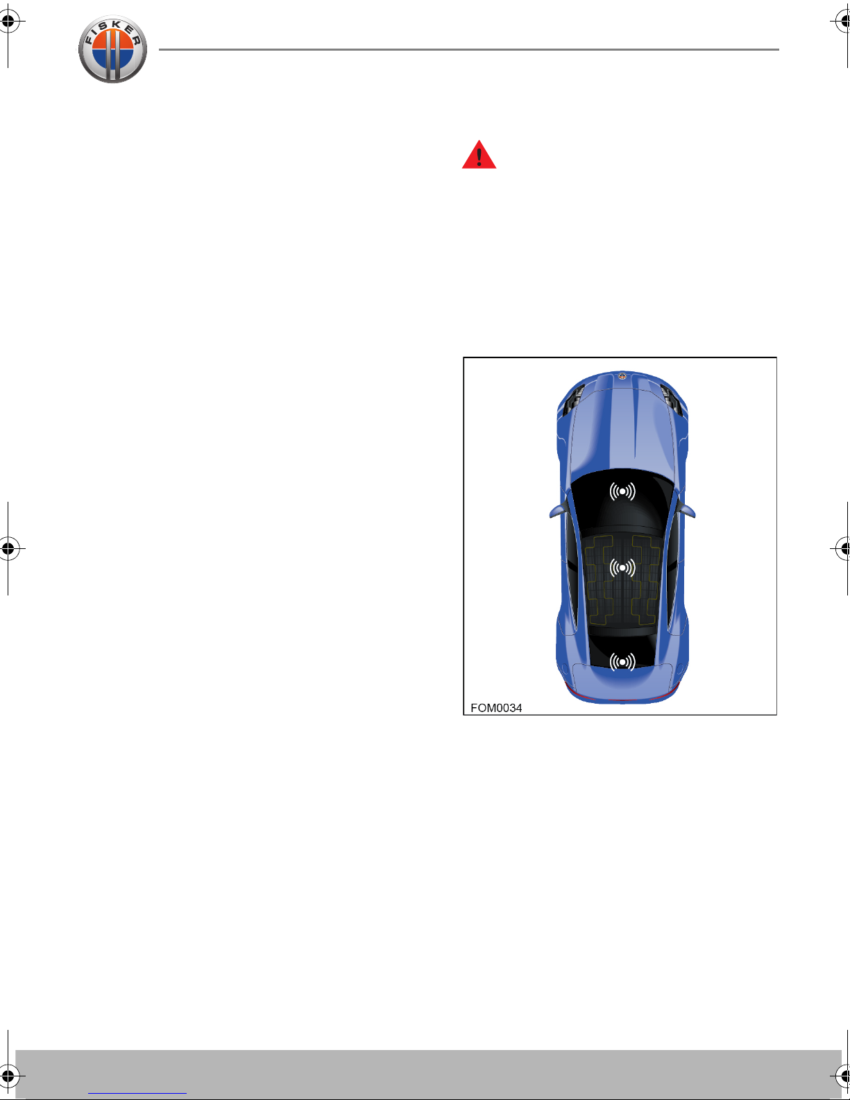
Transmitters which detect the presence of
the key fob are located in the following
locations on your vehicle:
1. Behind the touch-screen
2. Beneath the center console
3. Trunk - underside of the rear parcel shelf
Locking and Unlocking the Vehicle
3.4
Locking and Unlocking the Vehicle
REPLACING THE KEY FOB
BATTERY
If the vehicle detects that the key fob
battery is low an indicator light will
illuminate on the instrument cluster. Please
change the key fob battery as soon as
possible.
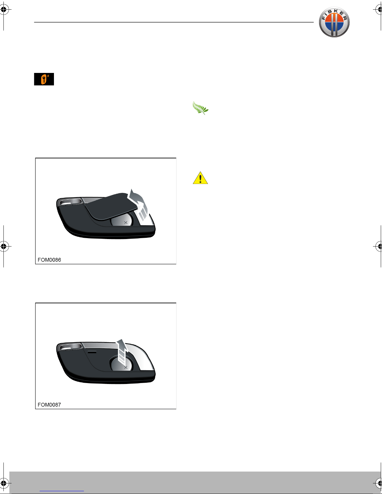
To change the key fob battery:
1. Place the key fob button side down on a
soft surface.
battery life. Wipe the battery clean
before fitting.
6. Re-assemble the two halves of the key
fob by aligning them and pressing them
together until they snap into place.
Used batteries must be disposed of
correctly, as they contain harmful
substances. Seek advice on disposal from
your local Fisker Retailer and/or your local
authority.
CARING FOR THE KEY FOB
CAUTION: The key fob contains
delicate electronic circuits and must
be protected from impact, water damage
and high temperatures. Avoid contact with
solvents, waxes and abrasive cleaners. Do
not leave the key fob exposed to direct
sunlight.
2. Using a small flat bladed tool, carefully
release the rear cover from the key fob.
3. Remove the rear cover.
4. Remove the battery.
5. Fit the new battery (type CR2032) with
the ‘+’ side facing upwards. If possible,
avoid touching the flat surfaces of the
battery because finger marks will reduce
TYPE APPROVAL
Hereby, Fisker Automotive, declares that
this remote vehicle entry system is in
compliance with the essential requirements
and other relevant provisions of Directive
1999/5/EC.
The Declaration of Conformity can be
obtained by writing to:
Lear Corporation Wireless Department,
21557 Telegraph Road,
Southfield,
Michigan, 48033
USA.
Locking and Unlocking the Vehicle
3.5
OPENING THE DOORS
Note: The exterior and interior door
releases are disabled when the vehicle is
locked.
From outside the vehicle
MASTER LOCK AND UNLOCK
SWITCH
To lock or unlock all the doors while in the
vehicle, press the master locking switch
located above the touch-screen.
With the vehicle unlocked, lightly press the
touch pad located behind the door handle
to release the door.
From inside the vehicle
To open the door from the interior of the
vehicle, press the switch marked OPEN on
the interior door panel.
AUTOMATIC LOCKING
Dependent upon configuration, the
vehicle's doors will either lock automatically
when a speed of 5 mph (8 km/h) is reached
or when D (Drive) or R (Reverse) is selected.
Note: This feature can be configured to your
personal preference via the touch-screen.
CHILD SAFETY LOCKS
Child safety locks are fitted to both of the
rear doors to prevent children from using
the rear door switches and accidentally
opening the doors when the vehicle is in
motion or parked.
The child safety locks are automatically
activated by inhibiting the operation of the
rear windows, see Rear window inhibit
page 5.9.
,
It is recommended that the child safety
locks are activated whenever children are
being carried in the rear seats.
Locking and Unlocking the Vehicle
3.6
Locking and Unlocking the Vehicle
EMERGENCY ACCESS
Emergency unlocking
If the key fob buttons fail to unlock, lock or
open the trunk, replace the key fob battery.
If the key fob still fails to unlock the vehicle,
you can unlock the passenger's door using
the key blade.
Note: The alarm is also deactivated when
the vehicle enters Accessory mode (as long
as a valid key fob is recognised).
Note: If this fails to work, use the keyless
start backup procedure. See Keyless start
backup procedure, page 5.21.
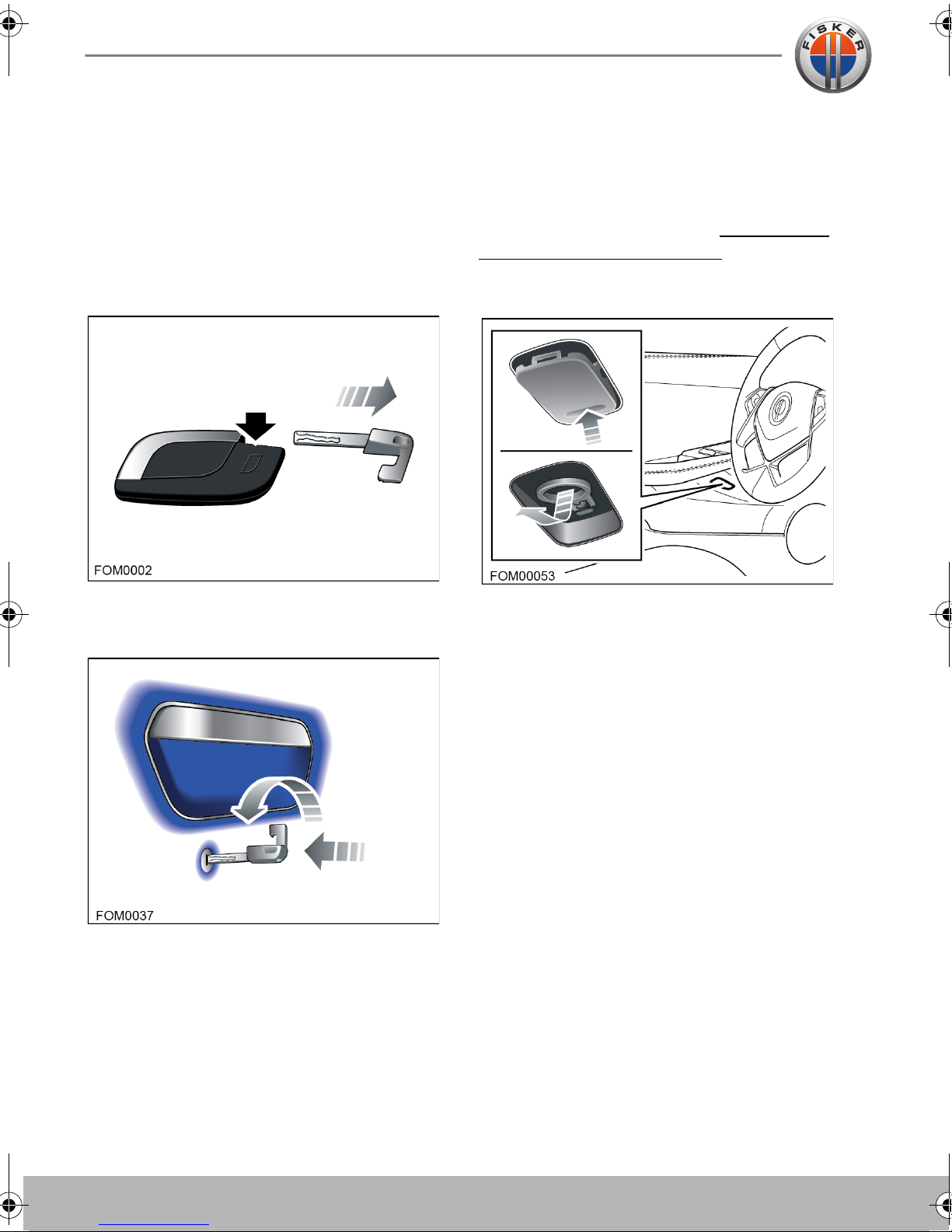
Manual door opening
Press the button on the reverse of the key
fob and slide the key blade free.
Insert the blade into the lock located on the
passenger door handle. Turn the key
counter clockwise to open the door.
The vehicle's alarm will sound when the
door is opened. To switch off the alarm,
press the brake pedal and press the Start/
Stop button. If a recognised key fob is
detected, the alarm will be deactivated and
the vehicle will enter Drive mode.
In the event of a power failure, each of the
doors can be manually opened from inside
the vehicle by pulling the release cable
located below the door handle.
To access the release cable, press the lower
edge of the cover below the door handle
and remove the cover.

Trunk
3.7
Trun k
OPENING THE TRUNK
To open the trunk, either press the trunk
release button on the key fob twice in quick
succession or press the trunk release
button on the left-hand dashboard closing
panel.
TRUNK INTERIOR RELEASE
HANDLE
Your vehicle is equipped with a mechanical
trunk release handle that provides a means
of escape in the event that a person
becomes locked inside the trunk. Adults are
advised to familiarize themselves with the
operation and location of the release
handle.
To close, firmly apply downward pressure to
the center of the trunk lid.
Note: The trunk release button is disabled if
the vehicle is locked, Valet mode is enabled
or when the vehicle’s speed exceeds 5 mph
(8 km/h).
A T-shaped handle is located inside the
trunk above the latch at the center of the
trunk lid. This handle is made using a
luminescent material that glows for hours
after a brief exposure to ambient light.
To open the trunk from the inside, pull the Tshaped handle and push up on the trunk lid.
Glove Compartment and Valet Mode
3.8
Glove Compartment and Valet Mode
Glove Compartment and Valet Mode
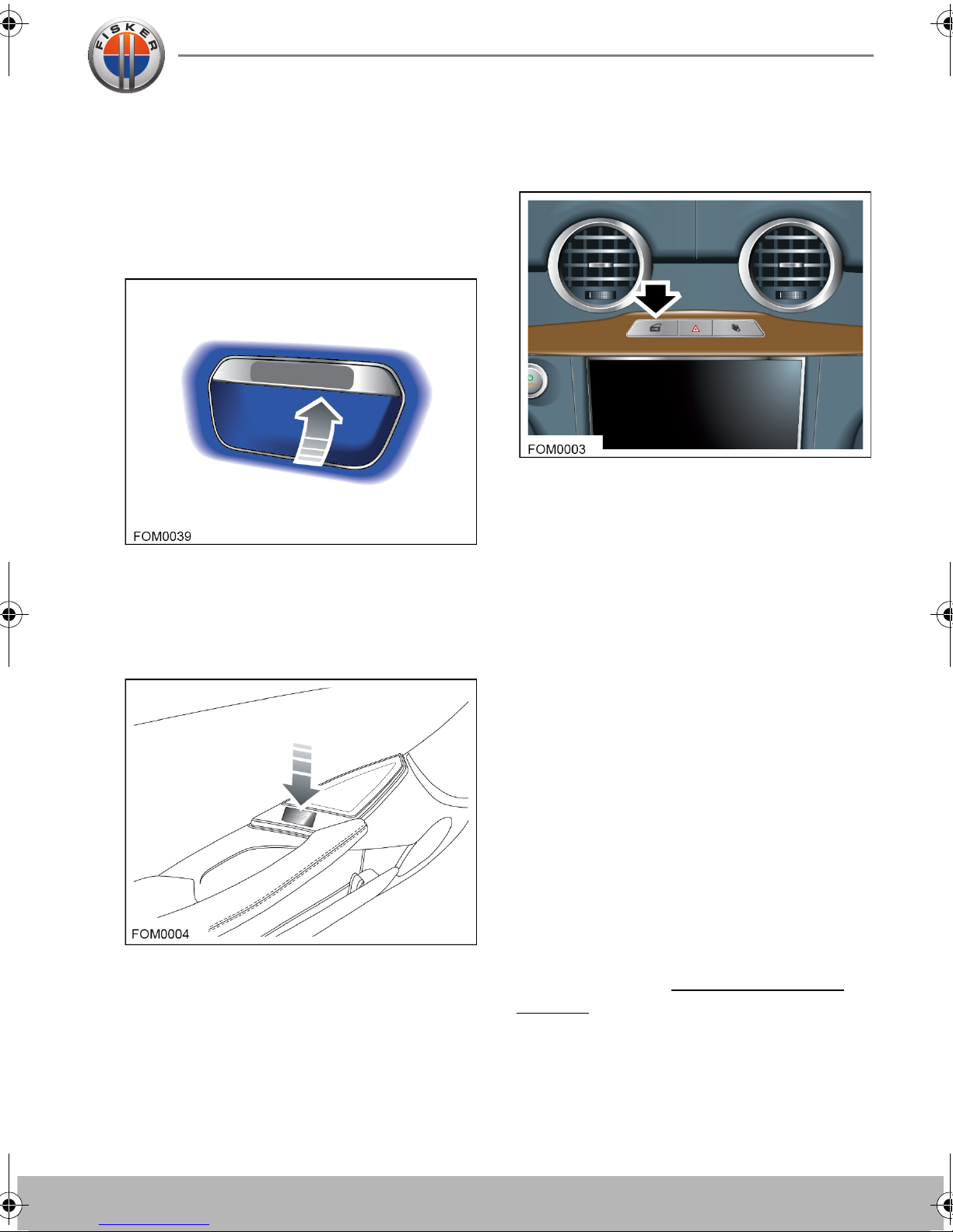
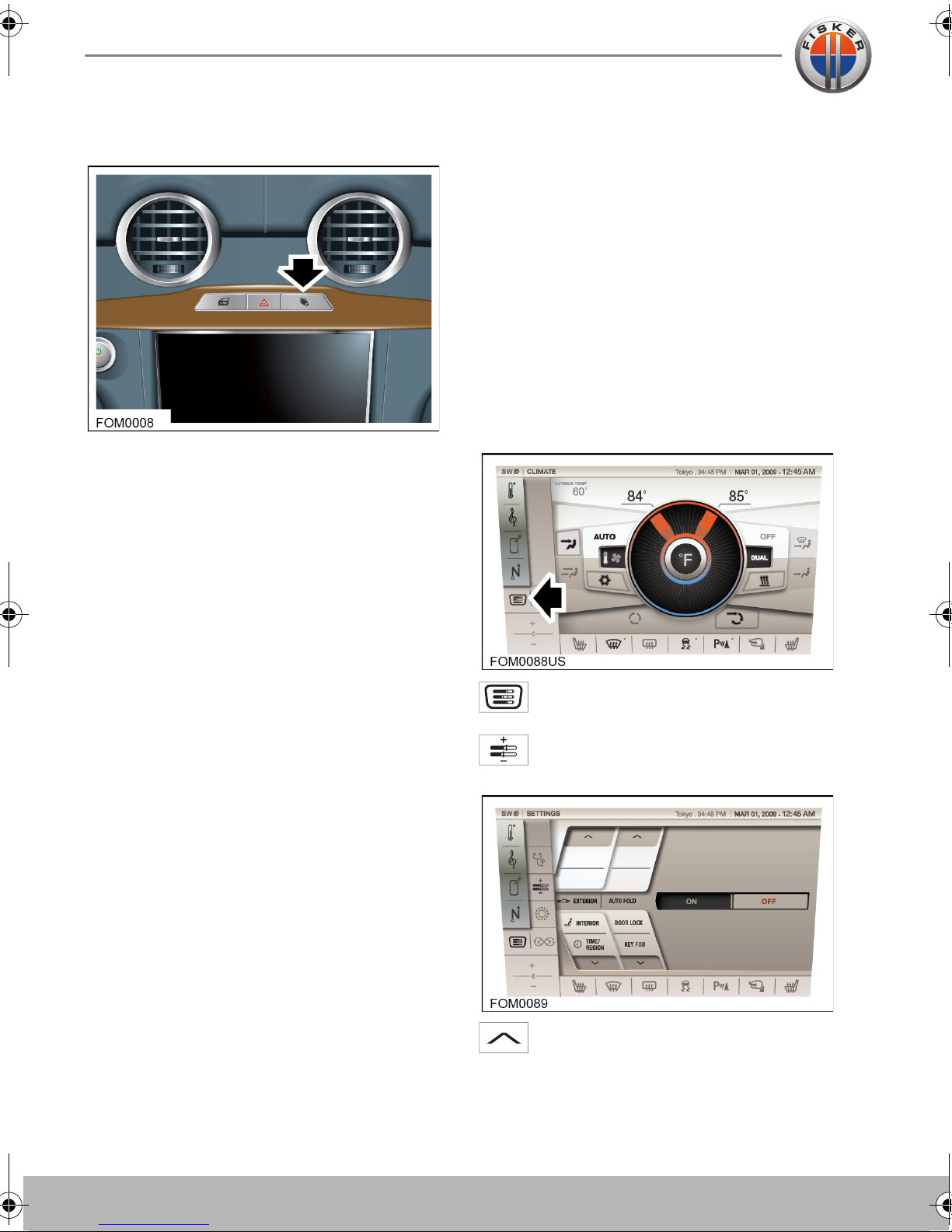
GLOVE COMPARTMENT
To open the glove compartment, press the
switch located above the touch-screen.
VALET MODE
For your peace of mind, your vehicle has a
Valet mode for those times that your vehicle
is parked by another person.
When Valet mode is active, access to the
trunk and glove compartment is restricted,
providing a secure location for storing
personal items.
Valet mode can only be deactivated by
entering a PIN (Personal Identification
Number).
Activating Valet mode
Note: The glove compartment cannot be
opened when the vehicle is locked or when
Valet mode is enabled.
To activate Valet mode, touch the
SYSTEM icon on the touch-screen.
Touch th e SETTINGS icon to access
the vehicle settings area.
Use the up arrows to change the
currently displayed settings to
EXTERIOR | VALET MODE.

Glove Compartment and Valet Mode
3.9
The current status for the Valet mode is
displayed in orange.
Enter a PIN using the on screen key pad and
then touch ENTER to activate Valet mode.
The status will change with ON being
highlighted in orange.
Deactivating Valet mode
The process to deactivate Valet mode is the
same as for activating it.
You will need to enter the same PIN to
disable Valet mode as was entered to
activate it.
Enter the PIN and then touch ENTER. If the
correct PIN code was entered, the status
will change with OFF being highlighted in
orange.
If you enter an incorrect PIN, a message is
displayed telling you that you’ve made an
invalid entry.
Note: If Valet mode is active, and you can’t
remember or don’t know what the PIN is to
deactivate it, you will need to take the
vehicle to a Fisker Retailer who will be able
to reset the system.


4.1
Occupant Safety
Seats and Steering Column
4.2 CORRECT SEATING POSITION
4.2 STEERING COLUMN POSITION
4.2 INTEGRATED HEADRESTS
4.3 ELECTRIC SEATS
4.3 SEAT HEATERS
4.4 DRIVER’S SEAT MEMORY
4.4 EASY ENTRY AND EXIT
Seat Belts
4.5 ABOUT SEAT BELTS
4.5 SEAT BELT SAFETY
4.6 WEARING THE SEAT BELT
4.7 WEARING SEAT BELTS WHEN
PREGNANT
4.7 SEAT BELT REMINDER
4.8 SEAT BELT TENSIONERS
4.8 CARING FOR SEAT BELTS
Child Restraints
4.9 CHILD RESTRAINTS
4.10 USING A NON LATCH CHILD
RESTRAINT
4.10 USING A LATCH CHILD RESTRAINT
4.11 UPPER TETHER STRAP
ANCHORAGES
Supplementary Restraint System
(SRS)
4.13 LOCATION OF AIR BAGS
4.13 IMPORTANT INFORMATION
4.14 HOW THE SYSTEM WORKS
4.15 DEPLOYMENT EFFECTS
4.15 OBSTRUCTION OF AIR BAGS
4.15 PASSENGER AIR BAG
DEACTIVATION
4.16 AIR BAG WARNING LABELS
4.16 SRS WARNING INDICATOR
4.17 AIR BAG SERVICE INFORMATION
4.17 VEHICLE MODIFICATIONS
4.2
Seats and Steering Column
Occupant SafetySeats and Steering Column
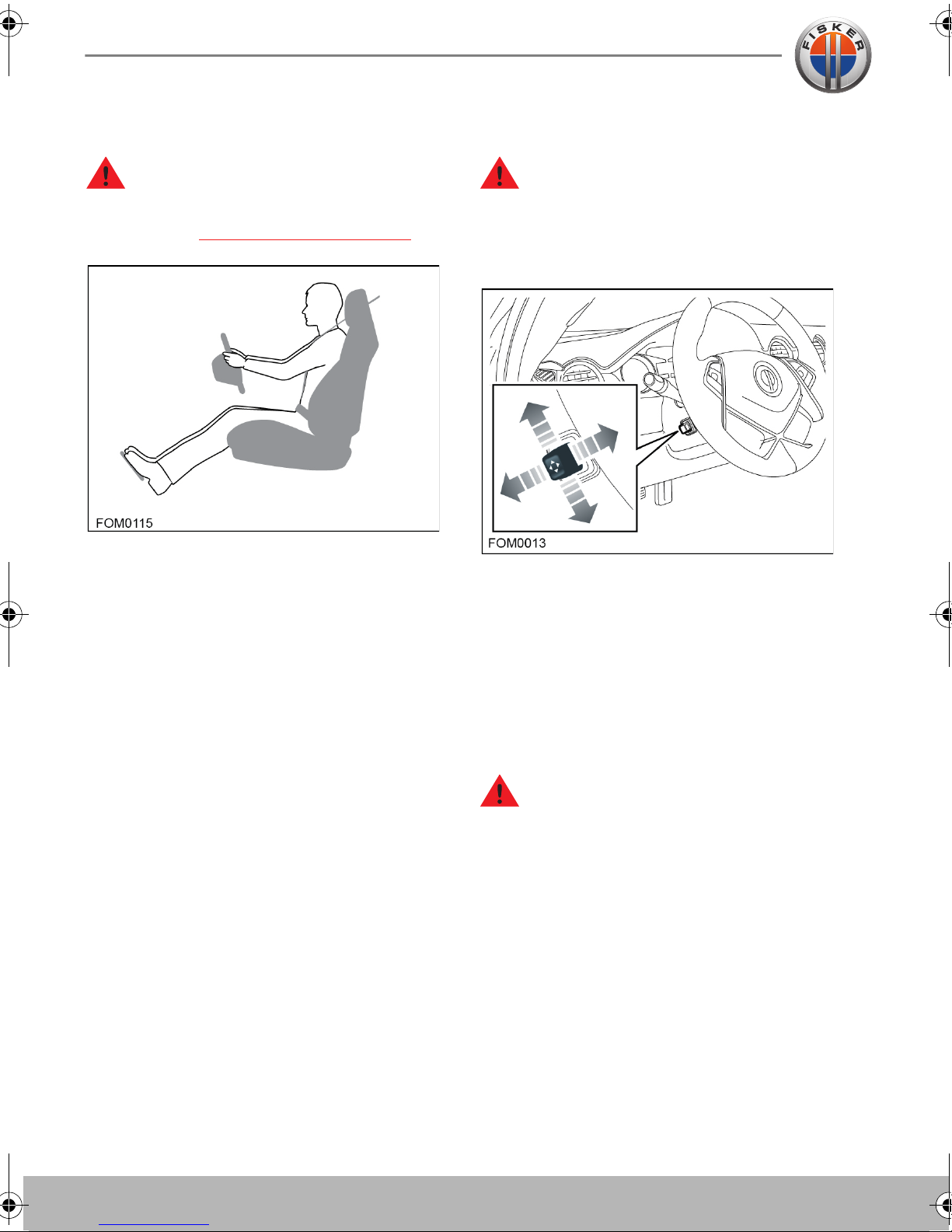
CORRECT SEATING POSITION
Seats and Steering Column
STEERING COLUMN POSITION
WARNING: Children under 4ft 5in
(1.35 m) tall or younger than 12 years
of age must be secured in a suitable child
restraint. See Child Restraints
To reduce the risk of injuries in the event of
an accident, observe the following:
• The driver and front passenger should
select a seat position that allows the
seat belt to be worn correctly, but is as
far away from the front air bags as
possible.
• Sit in an upright position with the base of
your spine as far back as possible and
the seatback reclined no more than 30
degrees.
• The position of the driver's seat must
allow the driver to drive the vehicle
safely. The distance from the driver's
seat to the pedals must be such that the
driver can fully depress the pedals. The
distance between the driver's chest and
the center of the air bag cover should,
ideally, be more than 10 inches
(254 mm). The driver's arms should be
slightly bent when holding the steering
wheel.
, page 4.9.
WARNING: Never adjust the steering
wheel position while the vehicle is in
motion. Doing so will reduce control of the
vehicle, and may cause unpredictable
steering movements.
With the vehicle stationary adjust the
steering column to the desired driving
position.
INTEGRATED HEADRESTS
The front and rear seats provide integrated
head restraints in the seatback. The head
restraints are not adjustable.
WARNING: To minimize the risk of
neck injuries in the event of a collision,
the driver and front seat passenger should
adjust the seatback inclination such that the
headrest is in an upright position.
• Position the seatbelt so that it is mid-
way between your neck and your
shoulder. Fit the strap tightly across your
hips, not across your stomach.
Seats and Steering Column
4.3
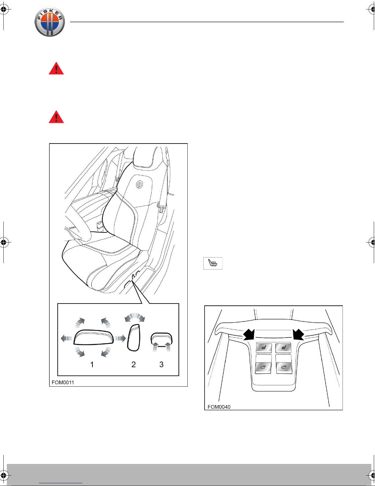
ELECTRIC SEATS
SEAT HEATERS
WARNING: Do not adjust any part of a
seat while the vehicle is in motion.
Vehicle movement may cause the seat to
suddenly shift, potentially causing injury or
loss of control.
WARNING: To prevent possible injury,
ensure that rear passengers cannot
become trapped as the seat moves.
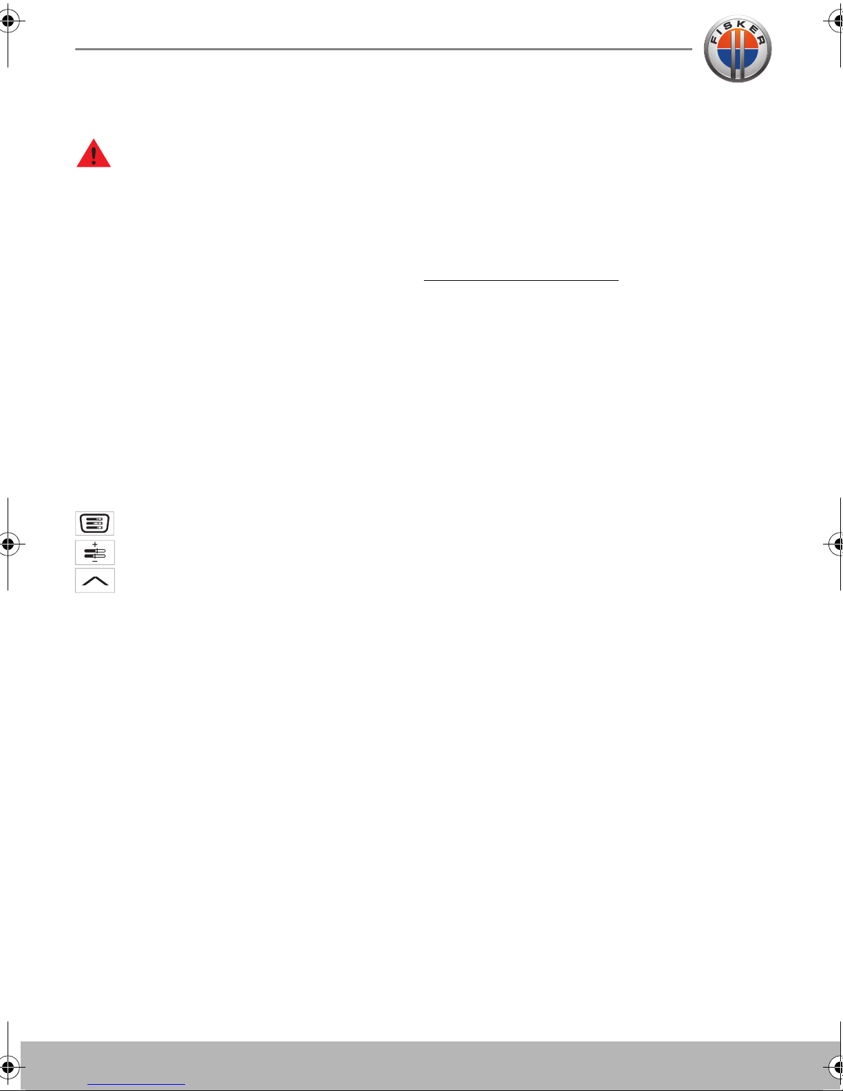
The seat heaters can be operated only
when the vehicle is in Drive mode. The seat
heaters will maintain a pre-determined
temperature according to the level selected.
The seats can be heated at three different
heat levels.
• Press once to operate at the highest
heat level. Three indicators will
illuminate.
• Press twice to operate at the medium
heat level. Two indicators will illuminate.
• Press a third time to operate at the
lowest heat level. A single indicator will
illuminate.
• Press a fourth time to turn off the
heaters.
Switching off the vehicle will automatically
turn off the seat heaters.
1. Cushion tilt adjustment and forward/
backward adjustment
2. Backrest adjustment
3. Lumbar support
Front seat heaters
To turn on a front heated seat, touch
the appropriate heated seat icon on
the touch-screen.
Rear seat heaters
To turn on a rear heated seat press the
appropriate switch on the rear center
console switch pack.
Seats and Steering Column
4.4
Seats and Steering Column
DRIVER’S SEAT MEMORY
WARNING: Before activating the seat
memory, ensure that the area
immediately surrounding the seat is clear of
obstructions and that all occupants are
clear of moving parts.
The vehicle can memorize two different
driver seat and steering column positions.
The seat and steering column position are
stored against the key fob currently used to
unlock the vehicle. When you unlock the
vehicle, the seat and steering column will
automatically adjust to the stored memory
position for that key fob.
Adjust the seat and steering column to the
desired position, and then store the
program in the seat memory via the touchscreen. See the procedure below.
Tou ch th e SYSTEM icon
Tou ch th e SETTINGS icon
Touch the up arrow to access the
Interior & Easy Entry/Exit selection.
EASY ENTRY AND EXIT
Entry and exit mode provides automatic
movement of the steering column and
driver’s seat making it easier to enter or exit
the vehicle.
Note: This feature can be enabled or
disabled via the vehicle’s touch-screen, see
Vehicle settings
Exit
When the Start/Stop button is pressed, the
steering column will move to the uppermost
tilt position and the driver’s seat will move to
the exit position.
Entry
When the driver’s door is closed and the
Start/Stop button is pressed, the steering
column and driver’s seat will return to the
previous position.
Note: If the steering column or driver’s seat
is adjusted during entry or exit operation,
automatic movement will stop.
, page 5.13.
Touch the Enable setting.
Touch the up arrows to access the
Memory/Seat Position selection.
Adjust the driver seat and steering wheel for
Driver #1.
Touch the lock/unlock buttons on Driver
#1’s key fob. This stores the memory
position for Driver #1.
Touch the Set selection (under the Primary
Seat Memory selection).
Repeat the above steps for the Secondary
Seat Memory.
 Loading...