

Fisher Scientific MARATHON 3000, MARATHON 3000R, 04-977-3000R, 04-977-3000, 04-977-3001 Operation Manuals
...
Artisan Technology Group is your source for quality
new and certied-used/pre-owned equipment
• FAST SHIPPING AND
DELIVERY
• TENS OF THOUSANDS OF
IN-STOCK ITEMS
• EQUIPMENT DEMOS
• HUNDREDS OF
MANUFACTURERS
SUPPORTED
• LEASING/MONTHLY
RENTALS
• ITAR CERTIFIED
SECURE ASSET SOLUTIONS
SERVICE CENTER REPAIRS
Experienced engineers and technicians on staff
at our full-service, in-house repair center
WE BUY USED EQUIPMENT
Sell your excess, underutilized, and idle used equipment
We also offer credit for buy-backs and trade-ins
www.artisantg.com/WeBuyEquipment
REMOTE INSPECTION
Remotely inspect equipment before purchasing with
our interactive website at www.instraview.com
LOOKING FOR MORE INFORMATION?
Visit us on the web at www.artisantg.com for more
information on price quotations, drivers, technical
specications, manuals, and documentation
Contact us: (888) 88-SOURCE | sales@artisantg.com | www.artisantg.com
SM
View
Instra
2000 Park Lane Pittsburgh, PA 15275
Tel. (800) 766-7000 Fax (800) 926-1166
MARATHON 3000(R)
General Purpose Centrifuge
Operation Manual
Model 3000 3L Ventilated Centrifuge
Cat. No. 04-977-3000 -- 120 VAC, 60 Hz
Cat. No. 04-977-3001 -- 220, 230, 240 VAC, 50/60 Hz
Model 3000R 3L Refrigerated Centrifuge
Cat. No. 04-977-3000R -- 120 VAC, 60 Hz
Cat. No. 04-977-30001R -- 220, 230, 240 VAC, 50 Hz
Cat. No. 04-977-30002R -- 230 VAC, 60 Hz
Part No. 04-977-3000M Rev. 4
Artisan Technology Group - Quality Instrumentation ... Guaranteed | (888) 88-SOURCE | www.artisantg.com

Table of Contents
Section 1 - Introduction Page
1.1 General Product Description...............................................................................................4
1.2 About This Manual.............................................................................................................5
1.3 Warnings, Cautions and Notes............................................................................................6
Section 2 - Installation
2.1 Receiving the Unit ..............................................................................................................7
2.2 Site Preparation...................................................................................................................7
2.3 Power Configuration............................................................................................................9
2.4 Moving the Unit.................................................................................................................10
2.5 The Front Panel (Keys and Displays)................................................................................11
Section 3 - Operation
3.1 Rotor and Accessories .......................................................................................................15
3.2 Starting and Stopping a Run..............................................................................................18
3.3 Stored Programs................................................................................................................19
3.4 Rotor Recognition System.................................................................................................21
3.5 3000R Refrigeration..........................................................................................................22
3.6 Diagnostic Messages and Error Codes..............................................................................23
Section 4 - Applications
4.1 Introduction.......................................................................................................................26
4.2 Speed and Force Tables....................................................................................................28
4.3 Derating Tables.................................................................................................................31
4.4 Chemical Resistance Tables..............................................................................................33
4.5 Decontamination Table.....................................................................................................34
4.6 RCF Nomograph...............................................................................................................35
Section 5 - Maintenance
5.1 Introduction.......................................................................................................................36
5.2 Care and Cleaning.............................................................................................................36
5.3 Cover Interlock Bypass.....................................................................................................39
5.4 Fuses Not Replaceable By Operator..................................................................................39
5.5 Condition of Returned Equipment ....................................................................................40
5.6 Warranty ...........................................................................................................................40
Section 6 - Specifications
Artisan Technology Group - Quality Instrumentation ... Guaranteed | (888) 88-SOURCE | www.artisantg.com
MARATHON Series Operation Manual
2

Copyright ©, 1998
Fisher Scientific
Printed in the USA
Artisan Technology Group - Quality Instrumentation ... Guaranteed | (888) 88-SOURCE | www.artisantg.com
MARATHON Series Operation Manual
3

1.1 General Product Description
Marathon series units are low-speed, general purpose
centrifuges, used in medical, industrial, and scientific
applications.
The Marathon 3000 Series is available in two models:
ventilated (3000) and refrigerated (3000R). Sections of
this manual that apply to the refrigerated version will be
designated 3000R or refrigerated only.
Both models accommodate swinging bucket style rotors of
either 4 x 750 mL or 6 x 250 mL. They can process a
variety of tubes, bottles, and microsample tubes. The 4 x
750 mL rotor can process both standard and deepwell
microplates. Also available are pear shape and short form
conical oil tube rotors.
Each centrifuge has an easy to use front panel that provides
two modes of operation: Manual and Programmed.
Manual mode is used for entering temperature (3000R
only), speed/force, and time values for individual runs.
Program mode allows you to define and save a maximum
of ninety-nine specific sets of run parameters, to recall and
reuse.
1 Introduction
Artisan Technology Group - Quality Instrumentation ... Guaranteed | (888) 88-SOURCE | www.artisantg.com
MARATHON Series Operation Manual
4

The Marathon Series features a maintenance-free, brushless
motor, and an easy-to-use front panel, which provides three
versatile timing modes: automatic timed run, short spin
(momentary), and hold (continuous mode). Acceleration
and brake rates may be controlled, to optimize runs: rapid
for fast separations or slow for delicate samples. Repeat
runs, with the same speed and time settings, may be
achieved at the touch of a key.
A fail-safe cover interlock insures that the cover is closed,
before a run can begin, and keeps the cover closed, until the
rotor has reached a safe low speed (below 100 rpm), even
in the event of a power failure.
The rugged steel cabinet and rigid construction provide
quiet operation and long term reliability.
1.2 About This Manual
The Operations Manual contains all of the information
needed to install, operate, and maintain a Marathon Series
centrifuge. Refrigerated and ventilated models operate
similarly, and any differences are highlighted and noted,
throughout this manual. This manual, also, contains speed
and force, derating, chemical resistance, and
decontamination tables. The last chapter lists the units’
specifications.
This manual is written for centrifuge operators. In addition
to operation information, it contains a few basic
troubleshooting techniques, and a chapter on maintenance.
This Operation Manual is not a guide for servicing
centrifuge units.
Artisan Technology Group - Quality Instrumentation ... Guaranteed | (888) 88-SOURCE | www.artisantg.com
MARATHON Series Operation Manual
5

1.3 Warnings, Cautions, and Notes
The terms warning, caution, and note have specific
meanings in this manual.
• A Warning advises against certain actions or situations
that could result in personal injury.
• A Caution advises against actions or situations that
could damage equipment, produce inaccurate data, or
invalidate a procedure.
• A Note provides useful information regarding an
operation, function, or procedure.
Artisan Technology Group - Quality Instrumentation ... Guaranteed | (888) 88-SOURCE | www.artisantg.com
MARATHON Series Operation Manual
6

2.1 Receiving the Unit
Fisher Scientific ships the centrifuge in a carton that
protects it from shipping hazards. Follow the unpacking
instructions on the carton. Be sure to complete and return
the postage-paid warranty card.
2.2 Site Preparation
The unit normally resides on a bench top. The 3000
(ventilated model) can be placed in a cold room (no colder
than 4°C), for processing temperature-sensitive samples.
When you remove the centrifuge from a cold environment,
do not operate for a minimum of two hours, so that any
condensation will evaporate.
Note: When used in a cold room environment, some
bearing noise may become evident. The bearing lubricant
thickens at low temperatures. As the centrifuge speeds up,
it is thinned and distributed more evenly. Once this occurs,
any noise should subside.
2 Installation
Artisan Technology Group - Quality Instrumentation ... Guaranteed | (888) 88-SOURCE | www.artisantg.com
MARATHON Series Operation Manual
7

The following table lists the physical dimensions for the
3000 and 3000R:
Sample Loading Height
Cover Closed Height
Cover Open Height
Width
Depth
A clearance of 8 cm (3 inches) should be provided on each
side of the unit, to ensure proper ventilation. Place the
centrifuge on a clean, dry surface, to make certain that the
suction feet at the bottom grip the surface firmly. Keep the
area beneath the unit free of debris and loose materials.
The resting surface must be level, to ensure quiet,
vibration-free operation. A rigid and stable location is
important. An improperly loaded centrifuge may vibrate or
move.
Warning: International Electrotechnical Commission
standard 1010 part 2-20 limits the permitted movement
of a laboratory centrifuge to 300 mm (12 in) in the unlikely
event of a disruption. Laboratory management procedures
should require that no person or any hazardous materials
enter within this boundary while the centrifuge operates.
3000R
14.7” (37.3 cm) 14.7” (37.3 cm)
16.5” (41.9 cm) 16.5” (41.9 cm)
41” (104.1 cm) 41” (104.1 cm)
30” (76.2 cm) 23.3” (59.1 cm)
25.8” (65.4 cm) 25.8” (65.4 cm)
3000
Artisan Technology Group - Quality Instrumentation ... Guaranteed | (888) 88-SOURCE | www.artisantg.com
MARATHON Series Operation Manual
8

2.3 Power Configuration
The Marathon Series uses AC power in different
configurations, appropriate for use throughout the world.
Please check the catalog number of the model that you
have purchased, to ensure that the machine you have is the
proper power configuration. For best results, the
refrigerated centrifuge, 3000R, should be used on a
dedicated line. Variations in line voltage or frequency
affect the unit’s speed and other characteristics. Less than
nominal line voltage may prevent the centrifuge from
reaching maximum published specifications of speed
and/or temperature. Power line voltage, at some locations,
may sag, when the refrigeration system turns on.
Power Cord The unit requires a grounded power supply (3 prong
outlet). If your facility does not have grounded power
outlets, arrange for a proper grounding. The power cord
plugs in on the left side of the unit.
Warning: Do not remove the grounding pin from the centrifuge
power cord. Do not use the bare wired power cord to attach a
power plug that does not have a grounding pin.
The power cord provided with the unit is correctly rated for the
highest current demand. This power cord should not be
interchanged with cords from equipment with lower current
demand. Exchange of power cords between equipment may
create a fire hazard.
Main Power Switch The main power switch is located on the left side of the
centrifuge, next to the power cord. Press this rocker switch
to power the unit on or off according to the picture below:
OFF ON
Artisan Technology Group - Quality Instrumentation ... Guaranteed | (888) 88-SOURCE | www.artisantg.com
MARATHON Series Operation Manual
9

Circuit Breaker The system provides an automatic circuit breaker, for
2.4 Moving the Unit
emergency situations, such as power surges, that could
damage the unit.
If the circuit breaker trips:
1. Unplug the unit.
2. Press the white button, on the left side of the unit.
3. Plug the unit back in.
Suction cups, at the bottom of the unit, keep it anchored to
the work surface. Keeping the unit stationary is a safety
feature.
To move the unit to a new location:
Caution: The unit can weigh up to 145 lb. (65.8 kg). Use
precaution when moving to avoid any injury.
1. Check that the new site meets the criteria in Section 2.2
before moving the unit.
2. Position a flat object, such as a tongue depressor, near a
suction cup at the bottom of the unit.
3. Lift up an edge of the cup, and insert the flat object far
enough to break the vacuum seal.
4. When all four cups are disengaged, lift the unit from the
work surface.
Caution: When the unit is in its new location, ensure that
the suction cups adhere correctly to the work surface.
Artisan Technology Group - Quality Instrumentation ... Guaranteed | (888) 88-SOURCE | www.artisantg.com
MARATHON Series Operation Manual
10
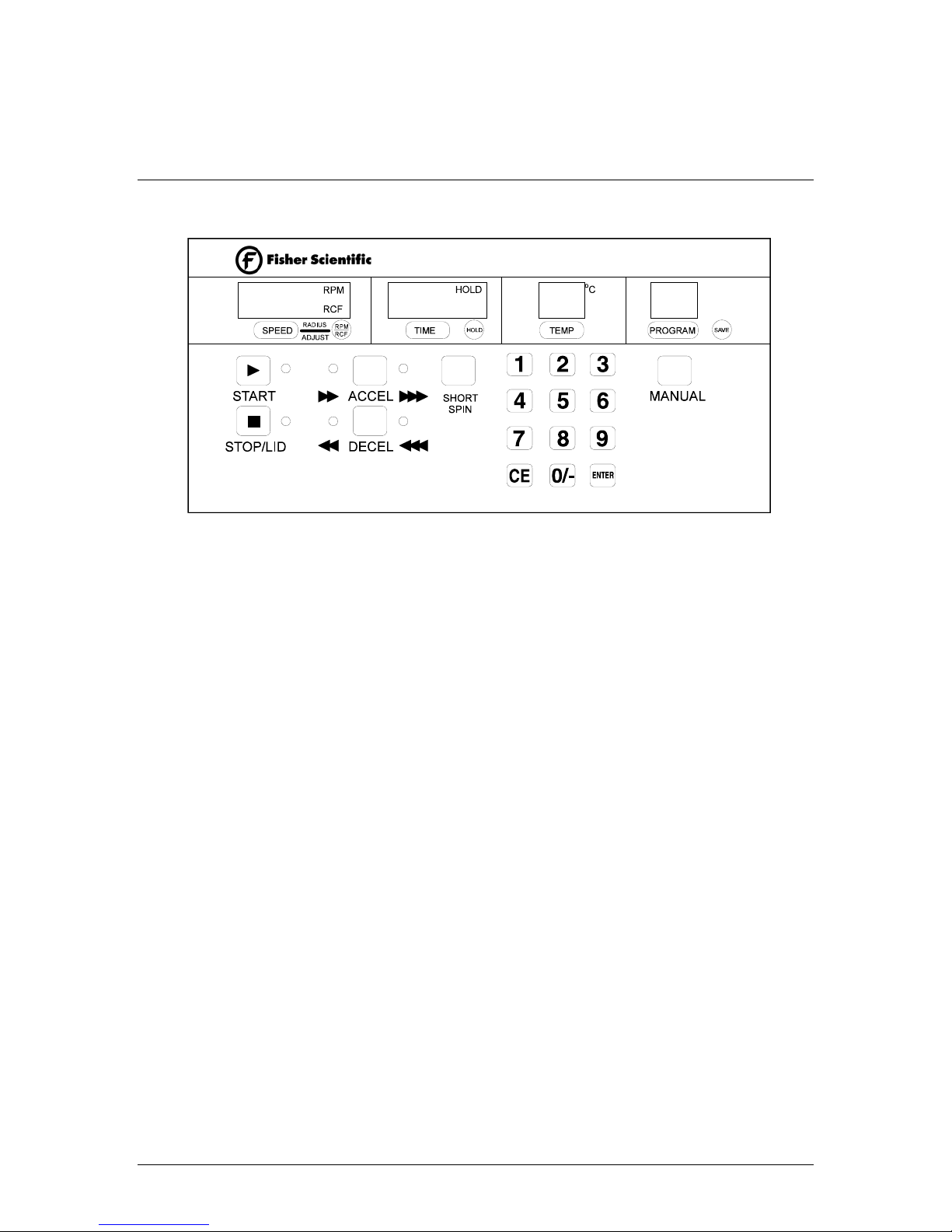
2.5 The Front Panel
The Front Control Panel
(3000R Model Shown)
The control panel contains numeric displays for RPM/RCF
(Speed/Force), Time, program, and Temperature
(Refrigerated only). These displays have two states or
modes: Actual (bright display) and Set (dim display).
In Actual mode (bright display), they indicate current run
conditions, such as:
• rotor speed or force
• elapsed time of, or time remaining in, the run
• actual temperature (Refrigerated only)
• program number
In Set mode (dim display), the display indicates the desired
settings for the run. Set mode is activated when:
• SPEED, TIME, TEMP., or PROGRAM are pressed
• briefly, at the start of a run
• briefly, after the unit is switched ON
The numeric displays can, also, display warning or error
messages (see Section 3.5). Descriptions of the displays
appear on the following pages.
Artisan Technology Group - Quality Instrumentation ... Guaranteed | (888) 88-SOURCE | www.artisantg.com
MARATHON Series Operation Manual
11

SPEED Speed Key: Pressing the SPEED key switches the display
from Actual to Set mode. Select the desired speed using the
numeric keypad, and then press ENTER. A selection must
begin before 5 seconds elapse or the display will revert to
the Actual reading.
RPM
RCF
Speed/Force key and display: The number in the
speed/force display represents the rotor speed in RPM or
force in RCF. Press this key to toggle between RPM and
RCF. When RPM is selected, the display indicates
revolutions per minute. When RCF is selected, the display
indicates relative centrifugal force. Use the numeric keys
to change the set speed or force. Select speed in increments
of 50 RPM, from 500 through 3,600 RPM (depending on
the max. allowable speed limit for the particular rotor).
Select RCF from 500 - 3,000 xg (depending on the max.
allowable RCF limit for the particular rotor) in increments
of 50 xg.
Rotor Radius SPEED & RPM/RCF: Pressing these keys together
allows the user to change the radius of rotation. Select the
radius using the numeric keypad, and then press ENTER.
Also see Section 3.4 Rotor Recognition System.
TIME
HOLD
SHORT
SPIN
Time key: Pressing the TIME key switches the display
from Actual to Set mode. Select the desired time using the
numeric keypad, and then press ENTER. A selection must
begin before 5 seconds elapse or the display will revert to
the Actual reading.
Time display: The number in the display indicates time.
Time is displayed as minutes:seconds up to 99 minutes.
The timer begins counting at the start of a run, i.e. when
START is pressed. In manual mode, the timer counts
down from the set point. In time HOLD or SHORT SPIN
modes, the timer counts up.
Hold display: The hold feature is used to initiate an
indefinite spin. Press the HOLD key so that HOLD
appears in the display. Pressing START will then begin a
run at the set parameters. The timer will count up, and the
run will not end until the STOP key is pressed.
Short Spin: The short spin is used for quick separations.
Pressing SHORT SPIN will begin a run at the set
parameters. The timer will count up, and the run will not
end until the SHORT SPIN key is released.
Artisan Technology Group - Quality Instrumentation ... Guaranteed | (888) 88-SOURCE | www.artisantg.com
MARATHON Series Operation Manual
12

TEMP
(3000R only)
PROGRAM
SAVE
MANUAL
Temperature key: Pressing the TEMP key switches the
display from Actual to Set mode. Select the desired
temperature using the numeric keypad, and then press
ENTER. A selection must begin before 5 seconds elapse or
the display will revert to the Actual reading.
Temperature display: The number in the display
represents temperature in degrees Celsius, from − 9 °C
through + 40 °C.
Note: If the Actual rotor chamber differs by more than 5°C
from a selected set point temperature, the °C display will
switch between the actual and set/programmed
temperatures, until the two temperatures come within 5°C.
Program key: Pressing the PROGRAM key switches the
display from Manual to Program mode.
Save key: This key saves the currently displayed desired
settings as stored programs 1 through 99 (see Section 3.3).
The numeric display shows the stored program number and
mode of operation (see Section 3.2).
Manual key: The manual returns the unit to manual
operation from Program mode.
Numeric Key Pad: The numeric key pad is used to change
the Set parameters for Speed/Force, Time, Temperature
(Refrigerated only) Rotor/Radius, or Program. When any
of the mode keys such as the SPEED, TIME, TEMP or
PROGRAM key is pressed, the numeric display switches
from Actual readings to Set parameters, without changing
them. The numeric key pad may be used to change the
parameter value. A selection must begin before 5 seconds
elapse or the display will revert to the Actual reading.
The CE key is used to clear a selection that has not yet
been entered to memory.
The 0/- key may be used to select a negative temperature.
Note: Temperature control range is specified from +4 °C
to ambient at maximum rated speed. Lower temperatures
can be achieved at less than maximum speed.
The ENTER key must be pressed after each parameter
selection to enter the value into memory.
Artisan Technology Group - Quality Instrumentation ... Guaranteed | (888) 88-SOURCE | www.artisantg.com
MARATHON Series Operation Manual
13
 Loading...