

Page 1
Introduction
WARNING
Explosions could result in serious injury or death:
Use in an explosive environment must be in accordance with the appropriate local,
national, and international standards, codes, and practices. Please review the
Reference Information and Product Certifications sections of the 475 Field
Communicator User’s Manual for any restrictions associated with safe use.
Electrical shock can result in serious injury or death.
WARNING
This device complies with Part 15 of the FCC Rules. Operation is subject to the
following two conditions: (1) this device may not cause harmful interference, and (2)
this device must accept any interference received, including interference that may
cause undesired operation.
©2009 Emerson Process Management. All rights reserved.
HART is a registered trademark of the HART Communication Foundation.
OUNDATION is a trademark of the Fieldbus Foundation.
F
IrDA is a registered trademark of the Infrared Data Association.
Bluetooth is a registered trademark of the Bluetooth SIG, Inc.
AMS Suite is a registered trademark of Emerson Electric Co.
The Emerson logo is a trademark and service mark of Emerson Electric Co.
All other marks are the property of their respective owners.
3
INTRODUCTION
The 475 Field Communicator Getting Started Guide provides basic guidelines,
precautions, and setup information for the 475 Field Communicator. It does not provide
in-depth instructions for configuration, diagnostics, maintenance, service,
troubleshooting, or Intrinsically Safe (IS) installations. Refer to the 475 Field
Communicator User’s Manual on the Resource CD or www.fieldcommunicator.com for
more instructions.
The 475 Field Communicator supports HART and F
you configure or troubleshoot in the field. Electronic Device Description Language
(EDDL) technology enables the 475 Field Communicator to communicate with a
variety of devices independent of device manufacturer.
OUNDATION fieldbus devices, letting
Page 2

4
475 Field Communicator Overview
475 FIELD COMMUNICATOR OVERVIEW
The portable 475 Field Communicator includes a color LCD touch screen, a Lithium
Ion battery (Power Module), a SH3 processor, memory components, and integral
communication and measurement circuitry.
When using the 475 Field Communicator to communicate with devices, follow all
standards and procedures applicable to the location. Failure to comply may result in
equipment damage and/or personal injury. Understand and comply with the sections in
this manual.
Working in a Hazardous Area
An Intrinsically Safe (IS-approved) 475 Field Communicator can be used in Zone 0
(FM and CSA only), Zone 1, or Zone 2, for Group IIC, and Class I, Division 1 and
Division 2, Groups A, B, C, and D locations.
An IS-approved 475 Field Communicator may be connected to loops or segments that
are attached to equipment located in Zone 0, Zone 1, Zone 2, for Group IIC; Zone 20,
Zone 21, Zone 22, and Class I, Division 1 and Division 2, Groups A, B, C, and D
locations.
IS-approved 475 Field Communicators are ordered with the KL option and have an
additional label on the back of the communicator that lists the approvals.
CAUTION
You can install or remove the Li-Ion battery in a hazardous area environment. You
cannot charge the battery in this environment because the power supply/charger
(00375-0003-0005) is not IS-approved.
Using the Touch Screen and Keypad
The touch screen and keypad let you select menu items and enter text. T ap the screen
with the provided stylus or use the up and down arrow keys on the keypad to select a
menu item. See Figure 1 for the location of the stylus. Double-tap the selected item on
the screen or press the right arrow key on the keypad to open a menu item.
CAUTION
Contact the touch screen using blunt items only, preferably the stylus included with the
475 Field Communicator. Sharp instruments, such as screwdrivers, can damage the
touch screen and void the warranty. Repairing the touch screen requires replacement
of the entire display assembly, which is possible only at an authorized service center.
Page 3

475 Field Communicator Overview
Figure 1. 475 Field Communicator
®
Interface (top)
IrDA
Touch Screen
Display
Strap attachment
(top)
HART and FOUNDATION
fieldbus Communication
Terminals (top)
Bluetooth® Light
5
Power Key and
Light
Strap
Attachment
(side)
Navigation Keys
(four arrow keys)
Tab Key
Li-Ion Battery
(back) and
System Card
(internal)
Stylus (in the
strap)
Illuminated by
Charge Indicator
Lights
Pressing the
Button (side)
Charge
Indicator
Button (side)
Backlight Key
Strap
Attachment
(side)
Enter Key
Function Key
and Light
(for multiple-key
combination
functionality)
Alphanumeric
Keypad
Green Power
Supply/Charger
Connector on
the Battery
(side)
Strap Attachment (side)Strap Attachment (side)
Page 4

6
475 Field Communicator Overview
Battery and Power Supply/Charger
Understand and follow the precautions below before using your battery or power
supply/charger.
• Protect the battery and power supply/charger from moisture, and respect operating
and storage temperature limits. See the 475 Field Communicator User’s Manual for
temperature limits.
• Do not cover the battery or power supply/charger, subject it to prolonged periods of
direct sunlight, or place it upon or next to heat-sensitive materials.
• Charge the battery with only the power supply/charger. The power supply/charger
should not be used with other products. Failure to comply may permanently damage
your 475 Field Communicator and void the IS approval and the warranty.
• Do not open or modify the battery or power supply/charger. There are no
user-serviceable components or safety elements inside. Opening or modifying them
will void the warranty and could cause personal harm.
• Follow all applicable regulations when transporting a Li-Ion battery.
Charging the Battery
Prior to first portable use, fully charge the Li-Ion battery. The power supply/charger has
a green connector to match the connector on the battery. The battery can be charged
separately or while attached to the 475 Field Communicator. A full charge takes
approximately two to three hours, and the 475 is fully operable when charging. An
overcharge condition will not occur if power supply/charger remains connected after
charging completes.
T o maint ain performance, charge the battery frequently , preferably after each use. Limit
full discharges, if possible. Additional information about maintaining the battery is in the
475 Field Communicator User’s Manual.
Power Supply/Charger Lights
Three colored lights are on the power supply/charger to indicate the conditions below.
Each light displays a different color.
Color Condition
Green The battery is fully charged.
Flashing green The battery is nearly fully charged.
Amber The battery is charging.
Flashing amber The power supply/charger is not connected to the
Flashing amber and red The remaining charge in the battery is low.
Red Charging cannot occur. Contact Technical Support for
475 Field Communicator.
more information.
Page 5
Installing the System Card and Battery
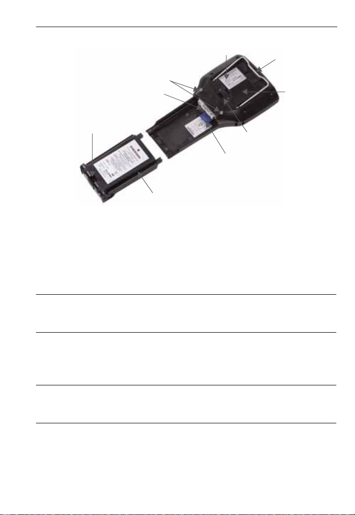
Figure 2. Back of the 475 Field Communicator
Main Unit Label
Battery Retaining Screws
Connector Pins
Stand
IS Label
Location
(KL Option)
7
Strap Attachment
Li-Ion Battery
Strap Attachment
System Card in the
System Card Socket
INSTALLING THE SYSTEM CARD AND BATTERY
1. Remove the protective rubber boot, if attached.
2. Place the 475 Field Communicator face down on a level, secure surface.
3. With the battery removed, slide the Secure Digital System Card (labeled System
Card), with the card contacts facing up, into the System Card socket until it clicks.
See Figure 2. The System Card socket is spring-loaded.
CAUTION
The System Card must be supplied by the 475 Field Communicator manufacturer.
Failure to comply will void the IS approval.
4. With the 475 Field Communicator still face down, ensure the two battery retaining
screws are loose.
5. Align the battery with the sides of 475 Field Communicator, and carefully slide the
battery forward until it is secure.
CAUTION
The connector pins may be damaged if the battery and 475 Field Communicator are
improperly aligned.
6. Carefully hand tighten the two battery retaining screws. (Do not over tighten, 0.5Nm
maximum torque load.) The tops of the screws should be nearly flush with the 475
Field Communicator.
Page 6

8
Removing the Battery and System Card
REMOVING THE BATTERY AND SYSTEM CARD
1. Remove the protective rubber boot, if attached.
2. With the 475 Field Communicator off, place it face down on a level, secure surface.
3. Loosen the two battery retaining screws until the top of each screw is above the top
of the 475 Field Communicator.
4. Slide the battery off the 475 Field Communicator.
CAUTION
The connector pins may be damaged if you pull the battery up rather than slide it off
the 475 Field Communicator.
5. Push the System Card into the System Card socket until it clicks and releases.
6. Slide the System Card out of the System Card socket.
STARTING THE 475 FIELD COMMUNICATOR
Before startup, ensure the 475 Field Communicator is not damaged, the battery is fully
seated, all screws are sufficiently tightened, and the communication terminals are free
of dirt and debris.
To start the 475 Field Communicator:
1. Press and hold the Power key on the keypad until the green light on that key blinks
(approximately two seconds). During startup, the 475 Field Communicator notifies
you if an upgrade on the System Card needs to be installed. The Field
Communicator Main Menu displays.
2. Use the touch screen or up and down arrow keys to select menu items. To open a
selected menu item, double-tap it or use the right arrow key.
3. To shut down, press the Power key and tap Shut down from the Power Switch
screen. Tap OK.
COMMUNICATING WITH PC APPLICATIONS
The IrDA interface, Bluetooth interface (if licensed), and a supported card reader let
the 475 Field Communicator or its System Card communicate with a PC. See Figure 1
for the location of the IrDA interface and the System Card. A card reader can only be
used with the Easy Upgrade Utility. See the 475 Field Communicator User’s Manual for
more information.
Page 7

Connecting to a Device
CONNECTING TO A DEVICE
Use the provided lead set to connect the 475 Field Communicator to the loop,
segment, or device. Three communication terminals for the lead set are on the top of
the 475 Field Communicator. Each red terminal is a positive connection for its protocol,
and the black terminal is a common terminal shared by both protocols. An access door
ensures that only one pair of terminals is exposed at any one time. Several markings
indicate which pair of terminals is for which protocol.
Only connections to a HART loop and F
the device is connected, double-tap HART Application or F
Application from the Field Communicator Main Menu. The appropriate device
description is also required. Refer to the latest version of the 475 Field Communicator
User’s Manual for details.
OUNDATION fieldbus segment are allowed. After
OUNDATION Fieldbus
CAUTION
The 475 Field Communicator draws approximately 12 mA from the fieldbus segment.
Ensure the power supply or barrier on the fieldbus segment has the capacity to provide
this additional current. If a fieldbus segment is drawing near the capacity of the
segment’s power supply , connecting the 475 Field Communicator may result in loss of
communication.
TECHNICAL SUPPORT
Contact your supplier or go to http://www.fieldcommunicator.com/supp.htm for
Technical Support contact information.
9
MAINTENANCE AND REPAIR
Any maintenance, repair, or replacement of components not listed below must be
performed by specially trained personnel at an authorized service center. You can
perform common maintenance procedures listed below:
• Cleaning the exterior. Use only a dry, lint-free towel or dampen the towel with a mild
soap and water solution.
• Charging, removing, and replacing the battery.
• Removing and replacing the System Card.
• Removing and replacing the stand.
• Ensuring that all exterior screws are sufficiently tightened.
• Ensuring that the communication terminal recess is free of dirt and debris.
Page 8

10
Waste Disposal
WASTE DISPOSAL
Products with the following label comply with the Waste Electrical and Electronic
Equipment (WEEE) directive, 2002/96/EC, which applies to European Union (EU)
member states only.
The label indicates this product should be recycled and not treated as
household waste. Customers in EU member states should contact their
Emerson sales representative for information on discarding any part of the
475 Field Communicator.
For customers in all other world areas, if it is necessary to discard any part of the 475
Field Communicator, follow the waste-disposal regulations applicable in your location.
HAZARDOUS SUBSTANCES
Products with the following label are lead-free and comply with the Restriction of the
Use of Certain Hazardous Substances in Electrical and Electronic Equipment (RoHS)
directive, 2002/95/EC, which applies to EU member states only.
The purpose of the directive is to limit the use of lead, cadmium, mercury,
hexavalent chromium, polybrominated biphenyl (PBB), and polybrominated
Pb
RoHS
diphenyl ether (PBDE) flame retardants in electronic equipment.
PRODUCT CERTIFICATIONS
Overview
All 475 Field Communicators have the main unit label (see Figure 2). Intrinsically Safe
(KL option) 475 Field Communicators also have a label opposite the main unit label. If
the 475 Field Communicator does not contain this label (NA option), it is not
Intrinsically Safe. See the 475 Field Communicator User’s Manual or
www.fieldcommunicator.com for additional approval information.
The Industry Canada (IC), Federal Communications Commission (FCC), and Radio
and Telecommunications Terminal Equipment (R&TTE) approvals apply to only 475
Field Communicators licensed for Bluetooth.
Approved Manufacturing Locations
Emerson Process Management — Leicester, England
IC
This Class A digital apparatus complies with Canadian ICES-003.
Page 9

Product Certifications
11
FCC
This equipment has been tested and found to comply with the limits for a Class A
digital device, pursuant to part 15 of the FCC Rules. These limits are designed to
provide reasonable protection against harmful interference when the equipment is
operated in a commercial environment. This equipment generates, uses, and can
radiate radio frequency energy and, if not installed and used in accordance with the
instruction manual, may cause harmful interference to radio communications.
Operation of this equipment in a residential area is likely to cause harmful interference
in which case the user will be required to correct the interference at his own expense.
Any modifications made to this device that are not approved by Emerson Process
Management may void the authority granted to the user by the FCC to operate this
equipment.
European Directive Information — CE Compliance
Electromagnetic Compatibility (2004/108/EC)
Tested to the EN 61326-1 specification.
R&TTE
This equipment complies with the Radio and Telecommunications Terminal
Equipment (1999/5/EC) Directive.
ATEX Directive (94/9/EC) (KL option only)
Emerson Process Management complies with the ATEX Directive. Applicable
standards are EN 60079-0, EN 60079-11, EN 60079-26, and EN 60079-27.
Specific ATEX Directive Information is located within this document and the
475 Field Communicator User’s Manual.
Hazardous Locations Certifications (KL option only)
The Intrinsic Safety approvals listed in this section include compliance with the FISCO
requirements.
North American Certifications
Factory Mutual (FM)
Intrinsically Safe for Class I, Division 1, Groups A, B, C, and D and Class I,
Zone 0, AEx ia IIC T4 (Ta = 50°C) hazardous locations when connected as
indicated in the control drawing 00475-1130 in the 475 Field Communicator
User’s Manual. See the control drawing for input and output parameters.
Canadian Standards Association (CSA)
Intrinsically Safe for use in Class I, Zone 0, Ex ia IIC T4 (Ta = 50°C) hazardous
locations when connected as indicated in the control drawing 00475-1130 in
the 475 Field Communicator User’s Manual. See the control drawing for input
and output parameters.
Page 10

12
Product Certifications
International Certification
IECEx
Certification No.: BVS 09.0012
Ex ia IIC T4 (-10°C ≤ Ta ≤ 50°C)
European Certifications
ATEX Intrinsic Safety
Certification No.: BVS 09 ATEX E 023
II 2 G (1 GD) Ex ia IIC T4 (-10°C ≤ Ta ≤ +50°C)
1180
HART Intrinsically Safe Electrical Parameters
Input Parameters
U
I
P
L
C
Output Parameters
U
I
F
The FISCO standard applies to the FM, CSA, IECEx, and ATEX certifications.
Intrinsically Safe FISCO
U
U
U
Intrinsically Safe Non-FISCO
U
U
L
= 30 Volt DC
i
= 200 mA
i
= 1.0 Watt
i
= 0
i
= 0
i
= 1.9 Volt DC
0
= 32 μA
0
OUNDATION fieldbus
= 17.5 Volt DC I
iIIC
= 17.5 Volt DC I
iIIB
= 1.9 Volt DC I0= 32 µA
0
= 30 Volt DC Ii = 380 mA Pi = 1.3 Watt
i
= 1.9 Volt DC I0= 32 µA
0
= 0 Ci = 0
i
= 215 mA P
iIIC
= 380 mA P
iIIB
= 1.9 Watt
iIIC
iIIB
= 5.3 Watt
 Loading...