


M-97
Operating Manual
Valve, Pedestal & Box Locator
Q U A L I T Y
Fisher detectors are renowned for their quality.
Each detector is hand crafted in the USA with pride
P E R F O R M A N C E
The worldwide underground utility industry relies on Fisher.
Our instruments are durable, dependable and locate deeper.
R E P U T A T I O N
Fisher produced the first patented metal detector in 1931. For
over 80 years, the Fisher logo has been a mark of excellence.
2 - YEAR LIMITED WARRANTY
Proof of purchase is required to make a claim under this warranty.
NOTE TO CUSTOMERS OUTSIDE THE U.S.A.
This warranty may vary in other countries, check with your
distributor for details.
Warranty does not cover shipping costs.
S E R V I C E
Should you have any questions or problems, contact:
FISHER RESEARCH LABORATORY
1465-H Henry Brennan, El Paso, Texas 79936
Tel 1800-685-5050 Fax 915-225-0336
www.fisherlab.com email: info@fisherlab.com
According to FCC part 15.21 Changes or Modifications made to this device
not expressly approved by the party responsible for compliance could void
the users authority to operate this equipment.
8700004000 Rev2 011111

CONTENTS
About Your M-97.......................................................................pg. 2
Features .....................................................................................pg. 3
Setting Up ..................................................................................pg. 3
Controls .....................................................................................pg. 4
Using Headphones ...................................................................pg. 5
Tuning ........................................................................................pg. 5
Searching ..................................................................................pg. 6
Specifications ...........................................................................pg. 7
Warranty ........................................................................ Back Cover
7
ABOUT YOUR M-97
Using ideas that you, our valued customers, have passed on to us, the
M-97 Valve and Box Locator stands as the new and improved addition
to our line of highly successful M-95 and M-96 Locators.
The M-97 is an all-metal metal detector that can search through
concrete and asphalt and was designed for finding buried or paved
over valves, boxes, or manhole covers, or any other concealed metallic
object. It also locates targets made of aluminum, brass and lead. Please
remember, like all Valve and Box Locators, the M-97 is a Metal Detector
which should not be used as a substitute for a Utility Line Tracer. Fisher
Research Laboratory manufactures a complete line of equipment for
Line Tracing (Pipe and Cable Tracing).
New to the M series is the ease with which the M-97 can be stored.
Just compact the lower stem, twist the search coil 90 degrees, and fold
the search coil flat. The M-97 fits easily into the optional carrying case.
In the Fisher tradition, the M-97 is affordable, tough, and simple to use
while providing maximum performance. A two year limited warranty
comes standard with the unit.
SPECIFICATIONS
Subject to improvement or modification without notice.
Output Frequencies of search coil ........... 4.5 kHz
Sensitivity ...............0.20 mv RMS for full scale
Sensitivity Adjustment Range ..................... 12:1
Output Indication . Meter 1 milliamp, ...... 0-100 linear scale
............................. Speaker ...................... 16-ohm impedance
............................. Headset (optional) ... 8-ohm impedance
............................. Audio Frequency ....... 450 Hz
Power Supply +9V supplies: ....................... (2) 9V batteries
Battery Life Alkaline .................................... 15-25 hours
Power Consumption .................................. (-9V) 13.8 mA
................................. At min. sound 8 mA
................................. At max. sound 50 mA
................................. At Audio threshold 17.5 to 18.5 mA
Search Coil Configuration ......................... Double-D
Weight with 8-inch search coil ................. 3.3 lbs. (1.5kg)
11-inch search coil ................. 3.9 lbs. (1.8kg)
Dimensions ............. 38 to 50 inches adjustable (96 to 127 cm)
Shipping Dimensions 6” x 13” x 35” (15.12 x 32.76 x 82.2 cm)
Fisher Research Laboratory does not warrant suitability to
specific use. Fisher Research Laboratory shall in no event
be liable for any direct, incidental, consequential or indirect
damages.
OPTIONAL ACCESSORIES:
Heaphones
Coil Covers
11” search coil
Hard carrying case
Vinyl carrying bag

36
SEARCHING
It is a good idea to establish a methodic search pattern. Avoid swinging
the M-97 like a golf club, swing the detector side to side keeping the
search coil the same distance above the ground. Your sweep pattern
should be a slow, half-circle motion. If you are searching for a small
target, it is a good idea to overlap your sweeps.
When the detector’s search coil starts to pass over a metal object,
the sound will increase and the meter readings will increase. Depending
upon the size and depth of the target, the target may appear (respond)
to be larger than it should. To get a visual outline of the target, you need
to reduce the sensitive of the M-97 by raising the coil and passing over
the target. This can help establish the edges of the target.
Another method that will give a visual outline is to purposely detune
the M-97. Move the coil away from the target. Slowly bring the search
coil toward the target. As the sound increases, press and release the
Retune Button. Continue to move the coil toward and eventually over
the target. The sound and meter readings will be more responsive as the
search coil passes over the target. You may need to repeat this step
more times if the target is at a shallow depth. Be aware that you can
loose responsiveness of the target by over reducing the Tuning Control
(sensitivity) of the M-97.
To reset the M-97 back to the balanced settings, lift the search coil off
the ground, and away from any metallic objects and press and release
the Retune Button. The M-97 will automatically retune to the original,
balanced settings.
• Two knobs and a pushbutton for simple operation
• Adjustable shaft with double locking stem
• Ground Effect Rejection VLF eliminates annoying or false signals
from wet ground foliage, pavement or mineralized ground
• High sensitivity for maximum penetration through soil, asphalt
or concrete
• Built-in Battery Test
• Pushbutton Tuning to quickly & easily maintain optimum sensitivity
• Ultra Slow Auto-Tune to stabilize ground tuning and minimize
frequency drift
• Identifies metallic objects by speaker sound and needle
movement
• Compact size for convenient storage
• Waterproof search coil
FEATURES
SETTING UP
The M-97 comes ready to use.
Extend the lower stem of the M-97 so that the search coil rests between 6 to 12 inches in front of your feet. Your arm should be straight
and relaxed with your grip held loosely.
Tighten the locking nut/compression nut at the bottom of the upper
stem.
When the proper length is selected, the excess cable should be wound
around the stem. This can be done by slightly loosening the locking nut
and turning the lower stem, or by removing the search coil and winding
the cable by hand. Be sure to leave some slack in the cable.
Check the batteries by turning the Mode control to Battery Test position and turning the Ground control to any number. A reading between
80 and 100 indicates the batteries are OK.
*With the 11” coil you must slide the lower stem completely out of the
upper assembly for the M-97 to properly fit in the hard carrying case.

4
5
CONTROLS
Meter
The meter of the M-97 serves
two purposes for the operation of the instrument. When
used in the battery test mode,
the meter gives a visual indication of the battery strength.
A reading between 80 – 100
is desirable. If the reading is
below 80, search depth and
ac curacy ca n decreas e.
Please change the batteries, if
necessary. (Note: The batteries must be inserted correctly for the M-97 to
operate. Match up the correct battery terminals with the markings on the
inside of the battery holder. Failure to do so will not damage the instrument,
however, the instrument will not function).
When searching with the M-97, the meter gives a visual indication to any
change occurring in the field of detection. This is primarily due to the coil
passing over or near a metal object, but can occur when the ground
mineral conditions change.
On/Off Ground Rejection Control
This control turns the M-97 on and off. It is used to electronically balance the
M-97 to compensate for the natural mineral content of the soil or ground
surface. When tuned properly, raising and lowering the search coil above
the ground will not cause a change in the meter reading or audio tone.
Mode Switch
This control is used to change the mode function of the Locator.
Battery Test
With the detector turned on, the Battery Test mode will indicate
battery strength. This is a no-load battery test.
Normal
This setting is used for the Turn On and Go mode. The Normal
Mode requires very little Ground Rejection adjustment.
High
This setting is used for increasing the sensitivity of the M-97,which also
increases the depth searching capabilities of the instrument.
Retune Button
When this button is depressed, the instrument will rebalance itself to the
instrument settings and prevailing ground conditions.
M-97 Control Panel
Using headphones (not included) improves battery life, and prevents
the sounds from bothering bystanders.
It also allows you to hear subtle changes in the sound more clearly,
particularly if searching in a noisy location. For safety reasons, do not
use headphones near traffic or where other dangers are present. This
device is to be used with interconnecting cables/headphone cables
shorter than three meters.
USING HEADPHONES
TUNING THE M-97
There are two methods to tune and balance the M-97. One method
is for quick and easy operation; the other will allow you fine tune the
detector for deeper searching and greater sensitivity.
Turn On and Go Method
Select an area that is free of metal near and under the search coil. Turn
on the M-97 by setting the Mode control to “Normal” and Ground control
to the position “5”. (Hint: If the M-97 is loud sounding when the instrument
is turned on, press and release the Retune Button to quiet the instrument).
Raise the search coil about 12 to 18 inches above the ground (dirt, concrete, asphalt, etc.), and press and release the Retune Button.
Lower the coil close to the ground. There should be little or no change
in the tone of the detector. If the M-97 changes tone when the coil is
lowered to the ground, there is either a metallic object near the coil that
is causing the instrument to respond, or the soil conditions are such that
the M-97 needs to be more precisely balanced.
Proceed with locating your targets.
Precision Tuning Method
(This method can be used for the “Normal” setting, and must be used
for the “High” setting).
Select an area that is free of metal near and under the search coil.
Turn on the M-97 by setting the Mode control to “Normal” and Ground
control to the position “5”. Raise the search coil about 12 to 18 inches
above the ground (dirt, concrete, asphalt, etc.), and press and release
the Retune Button. Note any change of sound. If there is no change, or
only a slight change, the M-97 is balanced and ready to search.
If the sounds changes: Sound increases – Slightly decrease the Ground
setting. Repeat above procedure. Sound decreases – Slightly increase
the Ground setting. Repeat above procedure.Repeat until no (or a
slight) change of sound occurs.

XLT-17
Operating Manual
Liquid Leak Detector
FISHER RESEARCH LABORATORY
1465-H Henry Brennan,
El Paso, Texas 79936
Tel 915.225.0333 Fax 915.225.0336
www.fisherlab.com email:info@fisherlab.com
8700725000 Rev.2 011211
Q U A L I T Y
Fisher detectors are renowned for their quality.
Each detector is hand crafted in the USA with pride
P E R F O R M A N C E
Treasure Hunters worldwide rely on Fisher.
Our detectors are durable, dependable, and search deeper.
R E P U T A T I O N
Fisher produced the first patented metal detector in 1931. For
over 70 years, the Fisher logo has been a mark of excellence.
2 - YEAR LIMITED WARRANTY
Fisher believes in the products we produce and backs this belief
with a 2 year limited warranty, Warranty may vary outside the
United States. See your dealer for details
Proof of purchase is required to make a claim under this warranty.
NOTE TO CUSTOMERS OUTSIDE THE U.S.A.
This warranty may vary in other countries, check with your distributor for details.
Warranty does not cover shipping costs.
According to FCC part 15.21 Changes or Modifications made to this device
not expressly approved by the party responsible for compliance could void
the users authority to operate this equipment.
S E R V I C E
Fisher is committed to providing you, our valued customer, with
superior service. Each and every instrument is rigidly tested
and carefully inspected during assembly and before shipment.
Should you have any questions or problems, contact:

CONTENTS
Introduction ................................................................................pg. 2
Instrument Set ..........................................................................pg. 3-4
Control Panel ...........................................................................pg. 5-6
Operating Instructions ...............................................................pg. 7
Use of the Multi-Sensor ...............................................................pg. 8
Specifications ........................................................................pg. 9-10
Warranty .......................................................................... Back Cover
2
INTRODUCTION
Fisher Research Laboratory has always been a leader in the field
of acoustical leak detection. From the early LT-10 through the
XLT-30, high quality sound amplification has been synonymous
with the Fisher name .
Fishers XLT-17 takes leak detection to a new level. The ultra-sensitive
Multi-Sensor, combined with high performance electronics and
crystal clear audio headphones provide a new standard for leak
detection equipment.

10
3
INSTRUMENT SET
1
7
2
4
5
3
6
NOTE: This equipment has been tested and found to comply with the limits
for a Class B digital device pursuant to Part 15 of the FCC Rules. These
limits are designed to provide reasonable protection against harmful
interference in a residential installation. This equipment generates, uses,
and can radiate radio frequency energy and, if not installed and used in
accordance with the instructions, may cause harmful interference to radio
communications. However, there is no guarantee that interference will
not occur in a particular installation. If this equipment does cause harmfill
interference to radio or television reception, which can be determined
by turning the equipment off and on, the user is encouraged to try and
correct the interference by one or more of the following measures:
- Reorient or relocate the receiving antenna.
- Increase the separation between the equipment and the receiver.
- Connect the equipment into an outlet on a circuit different from that
to which the receiver is connected.
- Consult the dealer or an experienced radio/TV technician for help.

4
9
INSTRUMENT SET
1. Control Box
All listening and filtering controls for the XLT-17 are contained in this sturdy
housing. The function of each control is described in the section entitled
“Control Panel.”
2. Multi-Sensor
Fisher’s MULTI-SENSOR has superior leak detection capabilities. In an
extremely compact design, the MULTI-SENSOR provides better sensitivity to leaks, improvs audio clarity, improvs sensor electronics, and less
interfering background noise. The MULTI-SENSOR is used for both the
ground microphone and direct contact applications – the one sensor
that does it all.
3. Sound Rods
Two different sizes are included with the XLT-17. Rods give the user various lengths for direct or indirect contact to pipes.
4. Multi-Sensor Handle
This handle is used with the Multi-Sensor
5. Sensor Cable
This cable attaches at the back of the Control Housing to any of the
various sensors, including the Multi-Sensor. Make sure the jack is fully
inserted and the lock nut is hand tightened.
6. Headphones
These headphones are designed to deliver the clearest sound with the
least distortion. The Volume knob can be used to adjust the audio level.
Unplugging the headphones will turn off the XLT-17. (When the XLT-17
is turned off, any modifications to the Volume and Filter will remain at
last settings.)
7. Carrying Strap/Housing Mounting Bracket
The attachment system for the XLT-17 consists of a plastic mounting
bracket that slides from the bottom of the control housing up to the bezel
around the faceplate. There are two slots for attaching an adjustable
strap that hangs around the neck of the user.
Subject to improvement or modification without notice.
Fisher Research Laboratory does not warrant suitability to specific use.
Fisher Research Laboratory shall in no event be liable for any direct, incidental, consequential or indirect damages.
SPECIFICATIONS
Operating Frequency
60 Hz – 6 kHz, Gain = 60 db
20 Hz – 60 Hz, Gain > 55 dB
Filter Types and Frequency Ranges:
All Pass:.......................60 Hz to 6 kHz
Low Pass: ....................
Adjustable cut-off frequency from 150 Hz to 2.4 kHz
High Pass: ...................
Adjustable pass band frequency from 150 Hz to 2.4 kHz
Band Pass: .................
Adjustable center frequency from 150 Hz to 2.4 kHz
Output Indications:
Audio ..........................High performance headphones (64 ohms)
Visual ..........................LCD bargraph and 2-digit numeric display
Grade of Protection .......Splash Proof
Battery Test .......................Automatic, real time battery level indicator
Battery Quantity/Type ....Two, 9 Volt alkaline
Battery Life .......................50 Hours (approximate)
Carrying Case Dimensions 21”x 6”x 14”
Weight: .............................10 lbs
STANDARD EQUIPMENT:
Hard Carrying Case
Operation Manual
Control Unit
Headphones
Muti-Sensor
Carry Strap/Housing Bracket
Sound Rods

8
5
CONTROL PANEL
POWER
This keypad turns the XLT-17 on or off. When the instrument is turned
off, all settings are stored in memory and retained for the next time the
XLT-17 is turned on.
VOLUME ARROW KEYPADS
Press Volume arrow keypad, to modify the volume and sensitivity of the
XLT-17. The arrow keys (up arrow/down arrow) increase or decrease the
audio signal to the headphones. Use the headphone volume knob to
reduce audio as desired.
MUTE
As the name applies, muting disengages the sound to the user. There is
also a control on all listening microphones. This keypad should be pressed
when the sensor is moved to prevent excessive noise to your ears.
FREQUENCY ARROW KEYPADS
These keypads allow the frequency range of the XLT-17 audio filters to
be modified.
Use of the Multi-Sensor
The multi-sensor was designed for locating leaks in all types of
surface conditions. The new sensor construction will allow leak
detection to be performed on hard surfaces such as concrete,
asphalt, tile, etc, as well as listening to water leaks under turf or
soft surfaces.
On hard sur fac es , the mut isensor sensor is used to pick up
the vibrations generated by a
buried ruptured pipe located
underneath sidewalks or paved
str e ets . The r ubb e r ho u sin g
diaphragm is designed to reduce
external sounds while the sensor
re sts on a h ar d sur fa ce an d
detects the vibrations traveling
underground.
When utilizing the multi-sensor for
direct connection to a pipe, or
listening to buried pipes located
in soft ground or under a turf
surface, you will need to use the
T-Handle and sound rods included
with the unit. Using a threaded
spacer provided on the extension
handle, carefully attach it directly
onto the Multi-Sensor. Assemble
the T- Handle by snapping both
the extension handle and sensor
handle sections together. Sound
rods are then secured to the
threaded coupler on the T- Handle
assy. Sound rod lengths will be
determined by its application.

6 7
FILTER
The XLT-17 has four different filtering modes.
AL (All Frequencies) – This is the No Filter feature of the XLT-17. No
modifications to the audio can be made with the arrow keys. Frequency
range of the All Frequency setting is from 60 Hz to 6 kHz. This mode is often
used to begin to listen for the leak noise.
(The following filter modes are often used to pinpoint the location of the
leak noise.)
HI (High Range) – This filtering mode allows the user to adjust the
response in the higher areas of the frequency range. Use the arrow keys
to increase or decrease this frequency response range.
LO (Low Range) – Similar to the previous filter mode, the lowpass
filter allows the user to listen to the lower areas of the frequency range.
The arrow keys are used to increase or decrease this frequency response
range.
FC (Frequency Choice) – This filter could also be called Frequency
Select. This mode allows tuning to the frequency that gives the user the
best audio response to the leak noise. The arrow keys are used to move
the cursor, selecting a narrow frequency band of choice.
CONTROL PANEL
OPERATING INSTRUCTIONS
Set Up
1. Assemble control housing, headset, and Multi-Sensor. The headset
must be plugged in for the XLT-17 to operate.
2. Familiarize yourself with the location of the mute keypad.
Remember to mute the XLT-17 when moving any sensor.
3. Press POWER keypad to turn on the XLT-17. The XLT-17 goes through
a five second warm up before the touch pads are functional. During
this time, the display screen gives information of battery level. A battery
reading under 5 volts will activate the “Low Battery” indicator. The XLT-17
allows some time between the “Low Battery” indicator and complete
system shut down to allow you to complete a job.
4. The XLT-17 always turns on to the last settings used.
5. Press the VOLUME arrow keys to modify headset volume. Use the ARROW keypads to increase or decrease the volume. The display screen
will show the volume level in a graph form.
6. Begin your leak detection search.
Modifications During Leak Search
Some leaks are small in size, and unrecognizable, or conditions are such
that very little leak sound can be recognized, so you may need to make
changes to the filter(s) in order to hear leaks. Depending upon the type
of pipe composition and soil (ground) type, different filter settings will
increase your ability to hear the leak sound.
Adjustment to the filter is done by pressing the FILTER keypad which will
allow you to scroll through four different filter types. Frequency range
modifications can be made to the HI, LO, and FC filters. As you are
choosing your filter, the display screen will give a visual display of the
filter type being used, and the frequency range of that filter. After your
selection and modification is made, theunit will automatically return to
the operating mode after a 5 second delay.
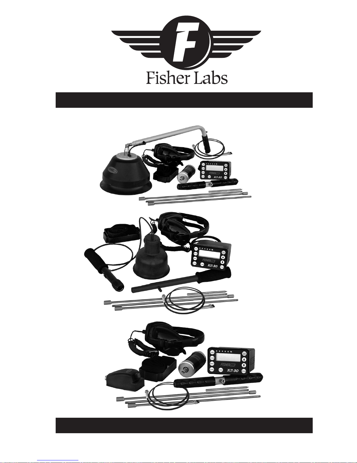
XLT-30
Acoustical Leak Detector
OPTION A
with BIG FOOT
OPTION B
with NEW MULTI-SENSOR
Operating Manual
F I S H E R R E S E A R C H L A B O R A T O R Y
OPTION C
with LITTLE FOOT

INTRODUCTION
Fisher Research Laboratory has always been a leader in the eld
of acoustical leak detection. From the early LT-10 through the
XLT-30, high quality sound amplication has been synonymous
with the Fisher name .
Fishers XLT-30 takes leak detection to a new level. Ultra sensitive
sound microphones, combined with a non-distortion amplication
system and crystal clear audio headphones make the XLT-30
the leak detector destined to set new standards for the leak
professional.
CONTENTS
Introduction ...............................................................................pg. 2
Headphones ..............................................................................pg. 2
Instrument Set ............................................................................pg. 3
Control Panel
.............................................................................pg. 6
Operating Instructions ..............................................................pg. 8
Use of the Multi-Sensor ..............................................................pg. 9
Specications ............................................................................pg. 11
2
USING HEADPHONES
Using headphones (not supplied) improves battery life, and
prevents the sounds from annoying bystanders.
It also allows you to hear subtle changes in the sound more
clearly, particularly if searching in a noisy location. For safety
reasons, do not use headphones near trafc or where
other dangers are present. This device is to be used with
interconnecting cables/headphone cables shorter than three
meters.

INSTRUMENT SET
OPTION A
6
8
2
4
3
1
7
5
7
2A
8
8
4
6
6
3
OPTION C
1
5
OPTION B
1
1
2B
5A
4
3

INSTRUMENT SET
OPERATING INSTRUCTIONS
1. Control Box
All listening and ltering controls for the XLT-30 are contained in this sturdy
housing. The function of each control is described in the section entitled
“Faceplate and Controls”.
2. Big Foot Sensor - OPTION A
Also known as the Ground Microphone, this sensor is to be used on hard
surfaces, concrete, asphalt, tile, etc. A fl exible rubber shield helps pre-
vent outside sounds from interfering with the sounds from the buried pipe.
Press and hold the red button near the handle to mute the audio from
the probe and suppress loud sounds when the probe is moved.
2A. Little Foot Assembly - OPTION C
About the size of a computer mouse, this small handheld sensor is designed for areas that the Big Foot Sensor can not t into. The Little Foot
assembly is normally used for leak detection inside buildings. Mute is
activated by pressing the button in front of the Little Foot Assembly.
2B. Multi-Sensor - OPTION B
Fisher’s new MULTI-SENSOR has superior leak detection capabilities. In an
extremely compact design, Fisher has achieved higher performance,
improved audio clarity, improved sensor electronics, and better sensitivity
to leaks with less background noise – all with heavy duty characteristics
of the trusted Big Foot. The MULTI-SENSOR is used for both the ground
microphone and direct contact applications – the one sensor that does
it all. Fisher’s NEW XLT-30 MULI-SENSOR combo sets the new standard for
leak detection.
Use of the Notch Filter
Occasionally, you may come across a sound that may be
masking or covering your ability to adequately hear any leaks.
This may be caused by nearby motors, fans, or many other
annoyances. (Unfortunately, the most common are sounds
caused by automobiles and traf c). The XLT-30 has a notch, or
reject feature, that will assist in eliminating that sound from your
frequency range.
Press the NOTCH pad, and use the ARROW pads to move the
cursor to the point where the annoying sound is eliminated or at
its weakest. Depress the RESUME pad to set the notch function.
(Hint: Depress the FILTER pad to go directly to the FILTER mode.
Now you can choose the type of Filter you wish to use AND still
have the annoying sound Notched).
Use of the Multi-Sensor (OPTION B)
Unlike our other sensor, this new sensor was designed for locating
leaks in all types of surface conditions. The new sensor construction
will allow leak detection to be performed on hard surfaces such
as concrete, asphalt, tile, etc, as well as listening to water leaks
under turf or soft surfaces.
3. Hydrophonic Cylinder Probe
This probe is a direct contact probe designed to make direct connection
to the pipe, or any portion of the pipe that is accessible. Used in any
combination of Sound Rods with the T-Handle, pipes can be accessed
to distances up to nearly 6 feet away.
Another feature of the Cylinder Probe is the ability to listen to pipe noise
in pipes that are buried in turf, or soft surfaces. Accurate pipe location
is essential for the placement of the Ground Rods as close to the pipe
as possible.
On top of the Cylinder Probe is a three position toggle switch for mute,
listen, and momentary listen. As with all mute controls, learn to use them
wisely.
When tightening the sounds rods to the Hydrophonic Probe, secure the
connector with a wrench as to not let it twist. Twisting of that connector
could damage wiring on the inside of the probe.
4 9
On hard surfaces, the muti-
sensor sensor is used to pick
up the vibrations generated
by a buried ruptured pipe
located underneath sidewalks
or paved streets. The rubber
h o u s i n g d i a p h r a g m i s
designed to reduce external
sounds while the sensor rests
on a hard surface and detects
th e vi bra ti ons t rav eli ng
underground.

INSTRUMENT SET
4. Sound
Rods
Two different sizes are included with the XLT-30. Rods give the user vari-
ous lengths for direct or indirect contact to pipes.
5. T-Handle
This handle is used primarily with the Cylinder Probe and the sound
rods.
5A. Multi-Sensor Handle
This handle is used with the Multi-Sensor
6. Headphones
These headphones are designed to deliver the clearest sound with the
least distortion. The Volume knob can be used to adjust the audio level.
Unplugging the headphones will turn off the XLT-30. When the XLT-30 is
turned off, any modications to the Volume, Notch, and Filter will return
to the factory presets.
7. Probe Cable (Option A & C)
This cable attaches at the back of the Control Housing to any of the
various probes. Make sure the jack is fully inserted and the lock nut is
hand tightened.
8. Carrying Strap/Housing Mounting Bracket
The attachment system for the XLT-30 consists of a plastic mounting
bracket that slides from the bottom of the control housing up to the bezel
around the faceplate. There are two slots for attaching an adjustable
strap that hangs around the neck of the user.

CONTROL PANEL
CONTROL PANEL
(The following lter modes have a frequency range from 60 Hz to 2.4
kHz)
HI (High Range) – This ltering mode allows the user to adjust the
response in the higher areas of the frequency range. Use the arrow keys
to increase or decrease this frequency response range.
LO (Low Range) – Similar to the previous lter mode, the lowpass
lter allows the user to listen to the lower areas of the frequency range.
The arrow keys are used to increase or decrease this frequency response
range.
FC (Frequency Choice) – This lter could also be called Frequency
Select. This mode allows tuning to the frequency that gives the user the
best response. The arrow keys are used to move the cursor, selecting a
narrow frequency band of choice
POWER
This pad turns the XLT-30 on or off. When the instrument is turned Off, all settings, or modications to settings default to the preset factory settings.
LIGHT
Press Light pad to turn the back light on or off. Prolonged use of the back
light will have minimal effect on the battery life of the XLT-30.
VOLUME
Press Volume pad to modify the volume of the XLT-30. The arrow keys (up
arrow/down arrow) increase or decrease the volume to the headphones.
Use the headphones volume knob to reduce audio as desired.
NOTCH
This control allows the user to mask or reject a small range of frequency
response. Its purpose is to eliminate a sound (i. e. motor, humming, fans,
etc.) that may be interfering with the leak sound. The notch setting can
be moved with the arrow keys.
FILTER
HOLD/MUTE
This dual purpose button is both a mute control and a peak hold
reset control.
Mute – As the name applies, muting disengages the sound to the
user. There is also a control on all listening microphones. Learn to use
this control to prevent excessive noise to your ears when the probes are
moved.
Hold – The display of the XLT-30 will show the highest sound level
recorded. This reading can be reset by pressing this pad. Resetting the
Peak Hold clears earlier readings of the Peak sound.
ARROW KEYS
These keys allow features of the XLT-30 to be modied.
RESUME
After any modication has been made to the XLT-30 (VOLUME, NOTCH,
or FILTER), depressing the RESUME will return the display screen back to
a Meter function (Sound Graph).
The XLT-30 has four different ltering modes.
AL (All Frequencies) – This is the No Filter feature of the XLT-30. No
modications to the signal can be made with the arrow keys. Frequency
range of the All Frequency setting is from 60 Hz to 6 kHz.
6 7

CONTROL PANEL
(The following lter modes have a frequency range from 60 Hz to 2.4
kHz)
HI (High Range) – This ltering mode allows the user to adjust the
response in the higher areas of the frequency range. Use the arrow keys
to increase or decrease this frequency response range.
LO (Low Range) – Similar to the previous lter mode, the lowpass
lter allows the user to listen to the lower areas of the frequency range.
The arrow keys are used to increase or decrease this frequency response
range.
FC (Frequency Choice) – This lter could also be called Frequency
Select. This mode allows tuning to the frequency that gives the user the
best response. The arrow keys are used to move the cursor, selecting a
narrow frequency band of choice
HOLD/MUTE
This dual purpose button is both a mute control and a peak hold
reset control.
Mute – As the name applies, muting disengages the sound to the
user. There is also a control on all listening microphones. Learn to use
this control to prevent excessive noise to your ears when the probes are
moved.
Hold – The display of the XLT-30 will show the highest sound level
recorded. This reading can be reset by pressing this pad. Resetting the
Peak Hold clears earlier readings of the Peak sound.
ARROW KEYS
These keys allow features of the XLT-30 to be modied.
RESUME
After any modication has been made to the XLT-30 (VOLUME, NOTCH,
or FILTER), depressing the RESUME will return the display screen back to
a Meter function (Sound Graph).

OPERATING INSTRUCTIONS
INSTRUMENT SET
Set Up
1. Assemble control housing, headset, and your choice of listening probe.
The headset must be plugged in for the XLT-30 to operate.
2. Press POWER pad to turn On the XLT-30. The XLT-30 goes through a ve
second warm up before the touch pads are functional. During this time,
the display screen gives information of battery level. A reading of 68 or
below will activate the “Low Battery” indicator. The XLT-30 does have a
usage buffer between the “Low Battery” indicator and complete system
shut down to allow you to complete a job.
3. The XLT-30 always turns on to the default settings. Volume is at the medium setting, lter is in the All Pass (no lter) mode, and the notch control
is at the midway point. The display screen will show the sound intensity
in a bar graph form (Sound Graph) and two digit display.
4. Familiarize yourself where the mute buttons (and pad) are. Remember
to mute the XLT-30 when moving any probe.
4. Sound
Rods
Two different sizes are included with the XLT-30. Rods give the user vari-
ous lengths for direct or indirect contact to pipes.
5. T-Handle
This handle is used primarily with the Cylinder Probe and the sound
rods.
5A. Multi-Sensor Handle
This handle is used with the Multi-Sensor
6. Headphones
These headphones are designed to deliver the clearest sound with the
least distortion. The Volume knob can be used to adjust the audio level.
Unplugging the headphones will turn off the XLT-30. When the XLT-30 is
turned off, any modications to the Volume, Notch, and Filter will return
to the factory presets.
5. Press the VOLUME pad to modify headset volume. Use the ARROW
pads to increase or decrease the volume. The display screen will show
the volume level in a graph form. Press the RESUME pad to exit volume
modication and return the display screen to the Sound Graph function. (Remember that the volume can be adjusted at the headphones
also.)
6. Begin your leak detection search.
Modications During Leak Search
Some leaks are small in size, and unrecognizable, or conditions are such
that very little leak sound can be recognized, so you may need to make
changes to the lter(s) in order to hear leaks. Depending upon the type
of pipe composition and soil (ground) type, different lter settings will
increase your ability to hear the leak sound.
Adjustment to the lter is done by pressing the FILTER pad which will
allow you to scroll through four different lter types. Frequency range
modications can be made to the HI, LO, and FC lters. As you are
choosing your lter, the display screen will give a visual display of the
7. Probe Cable (Option A & C)
This cable attaches at the back of the Control Housing to any of the
various probes. Make sure the jack is fully inserted and the lock nut is
hand tightened.
8. Carrying Strap/Housing Mounting Bracket
The attachment system for the XLT-30 consists of a plastic mounting
bracket that slides from the bottom of the control housing up to the bezel
around the faceplate. There are two slots for attaching an adjustable
strap that hangs around the neck of the user.
lter type being used, and the frequency range of that lter. After your
selection and modication is made, depress the RESUME pad to return
to the Sound Graph function of the display screen.
8 5

OPERATING INSTRUCTIONS
Use of the Notch Filter
Occasionally, you may come across a sound that may be
masking or covering your ability to adequately hear any leaks.
This may be caused by nearby motors, fans, or many other
annoyances. (Unfortunately, the most common are sounds
caused by automobiles and traf c). The XLT-30 has a notch, or
reject feature, that will assist in eliminating that sound from your
frequency range.
Press the NOTCH pad, and use the ARROW pads to move the
cursor to the point where the annoying sound is eliminated or at
its weakest. Depress the RESUME pad to set the notch function.
(Hint: Depress the FILTER pad to go directly to the FILTER mode.
Now you can choose the type of Filter you wish to use AND still
have the annoying sound Notched).
Use of the Multi-Sensor (OPTION B)
Unlike our other sensor, this new sensor was designed for locating
leaks in all types of surface conditions. The new sensor construction
will allow leak detection to be performed on hard surfaces such
as concrete, asphalt, tile, etc, as well as listening to water leaks
under turf or soft surfaces.
On hard surfaces, the muti-
sensor sensor is used to pick
up the vibrations generated
by a buried ruptured pipe
located underneath sidewalks
or paved streets. The rubber
h o u s i n g d i a p h r a g m i s
designed to reduce external
sounds while the sensor rests
on a hard surface and detects
th e vi bra ti ons t rav eli ng
underground.

USE OF THE MULTI-SENSOR (OPTION B)
INSTRUMENT SET
When utilizing the multi-sensor for direct
connection to a pipe, or listening to buried
pipes located in soft ground or under a
turf surface, you will need to use the THandle and sound rods included with the
unit. Using a threaded spacer provided on
the extension handle, carefully attach it
directly onto our sensor probe. Assemble
the T- Handle by snapping both the
extension handle and probe handle
sections together. Sound rods are then
secured to the threaded coupler on the
T- Handle assy. Sound rod lengths will be
determined on its application.
OPTION A
SPECIFICATIONS
NOTE: This equipment has been tested and found to comply with the limits
for a Class B digital device pursuant to Part 15 of the FCC Rules. These
limits are designed to provide reasonable protection against harmful
interference in a residential installation. This equipment generates, uses,
and can radiate radio frequency energy and, if not installed and used
in accordance with the instructions, may cause harmful interference to
radio communications. However, there is no guarantee that interference
will not occur in a particular installation. If this equip ment does cause
harm ll interference to radio or television reception, which can be
determined by turning the equipment off and on, the user is encouraged
to try and correct the interference by one or more of the following
measures:
- Reorient or relocate the receiving antenna.
- Increase the separation between the equipment and the receiver.
- Connect the equipment into an outlet on a circuit different from that
to which the receiver is connected.
1
- Consult the dealer or an experienced radio/TV technician for help.
10

SPECIFICATIONS
Subject to improvement or modication without notice.
Operating frequency: 60 Hz – 6 kHz, Gain = 95 db
20 Hz – 60 Hz, Gain > 90 dB
Filter types and frequency ranges:
All Pass: 60 Hz to 6 kHz
Low Pass: ....................... Adjustable cut-off frequency from 150 Hz to 2.4 kHz
High Pass: ....................... Adjustable pass-band frequency from 150 Hz to 2.4 kHz
Band Pass: ..................... Adjustable center frequency from 150 Hz to 2.4 kHz
Notch Filter: ...................
Can be used simultaneously with any lter option
Indication of output:
Audio: ............................ High performance head phones (64 ohms)
Visual: ............................. LCD bar graph display w/2 digit numerical read out.
Grade of protection: .................... Splash proof
Battery test..................................... Automatic
Type of Battery/Quantity ............. Alkaline 9 volt, 2
Battery life: ..................................... Approximately 50 hours
Adjustable center frequency rejection from 150 Hz to 2.4 kHz
WEIGHT:
Option “A” Option “B” Option “C”
19 lbs 10 lbs 9.5 lbs
ACCESSORIES:
Option “A” Option “B” Option “C”
Little Foot Big Foot Big Foot
Multi-Sensor Hydrophonic Cylinder Probe Multi-Sensor
Little Foot
STANDARD EQUIPMENT:
Option “A” Option “B” Option “C”
Plastic case Plastic case Plastic case
Operation manual Operation manual Operation manual
Control unit Control unit Control unit
Head phones Head phones Head phones
Big Foot Multi-Sensor Little Foot
Hydrophonic Cylinder Probe Carry Strap Hydrophonic Cylinder
Probe
“T” Handle Housing Bracket Probe Cable Assembly
Probe Cable Assembly Probe Cable Assembly “T” Handle
Carry Strap Sound Rods Carry Strap
Housing Bracket Housing Bracket
Sound Rods Sound Rods
Fisher Research Laboratory does not warrant suitability to specic use.
Fisher Research Laboratory shall in no event be liable for any direct, incidental, consequential or indirect damages.
11

Q U A L I T Y
Fisher detectors are renowned for their quality.
Each detector is hand crafted in the USA with pride
P E R F O R M A N C E
The worldwide underground utility industry relys on Fisher.
Our instruments are durable, dependable, and locate deeper.
R E P U T A T I O N
Fisher produced the rst patented metal detector in 1931. For
over 70 years, the Fisher logo has been a mark of excellence.
2 - YEAR LIMITED WARRANTY
Fisher believes in the products we produce and backs this belief
with a 2 year limited warranty.
Proof of purchase is required to make a claim under this warranty.
NOTE TO FOREIGN COUNTRY CUSTOMERS
This warranty may vary in other countries, check with your
distributor for details.
Factory warranty follows the channel of distribution.
Warranty does not cover shipping costs.
S E R V I C E
Fisher is committed to providing you, our valued customer, with
superior service. Each and every instrument is rigidly tested
and carefully inspected during assembly and before shipment.
Should you have any questions or problems, contact:
FISHER RESEARCH LABORATORY
1465-H Henry Brennan,
El Paso, Texas 79936
Tel 915.225.0333 Fax 915.225.0336
www.sherlab.com email:info@sherlab.com
FRL#8700721 04-29-09
F I S H E R R E S E A R C H L A B O R A T O R Y
 Loading...