

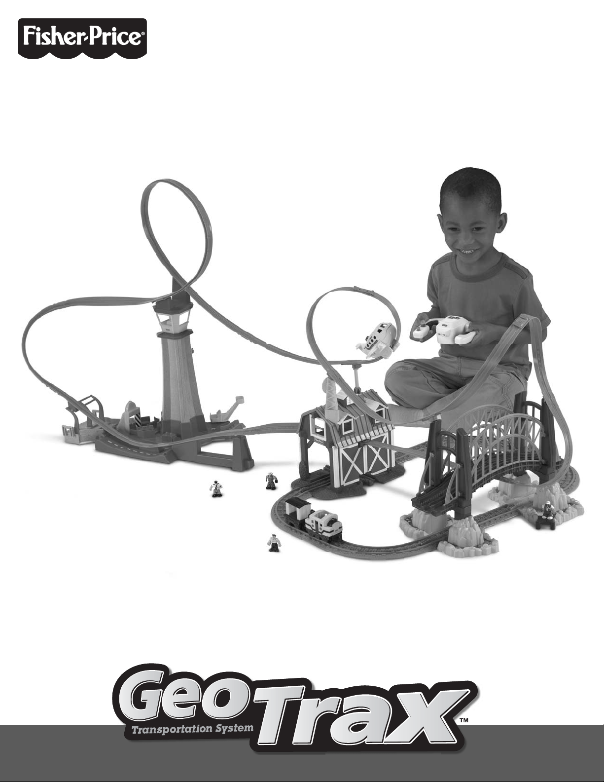
Page 1
www.fisher-price.com
www.fisher-price.com
N9993
N9993
Page 2
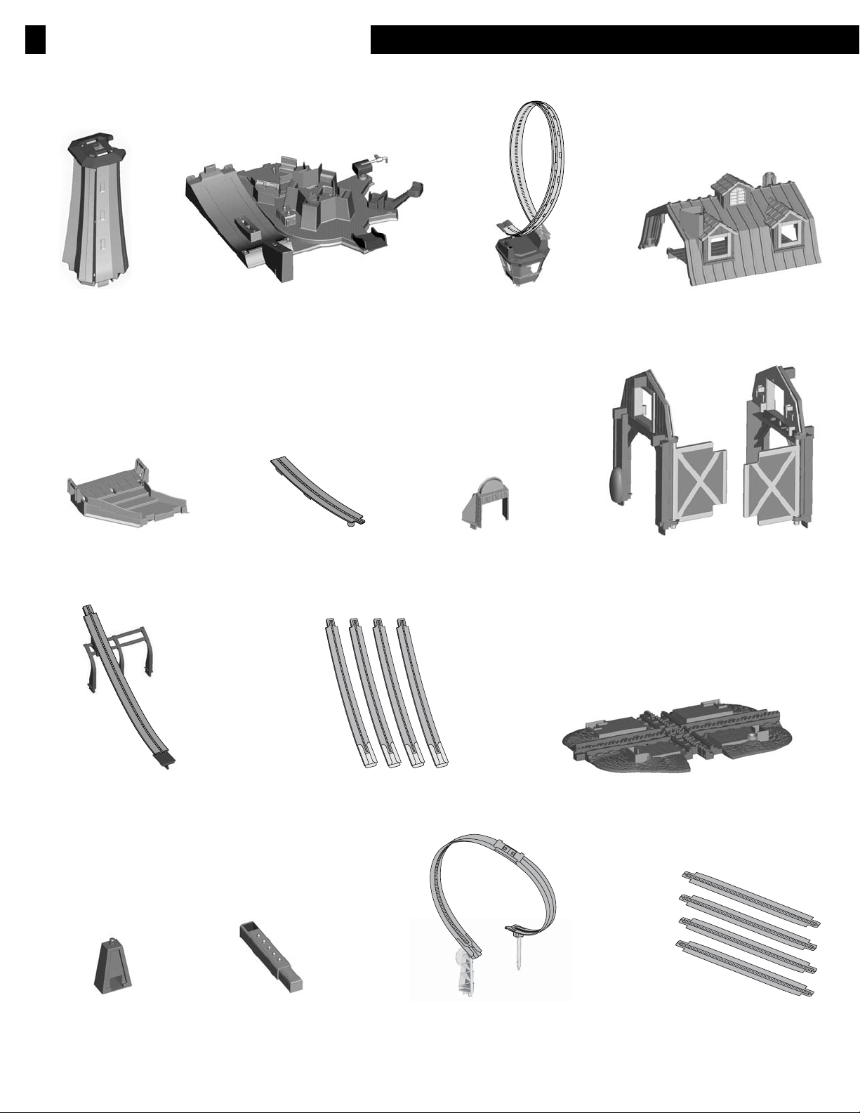
Assembled Parts
Terminal Base
Loading Station Security Gate
Air Track with Tabs
Traffic Control TopMain Tower
Barn Roof
2 Barn Walls
Air Track with Support
Trestle Base
Trestle Post
4 Air Tracks with Connectors
Windmill and Smokestack Track
2
Barn Base
4 Air Tracks
Page 3
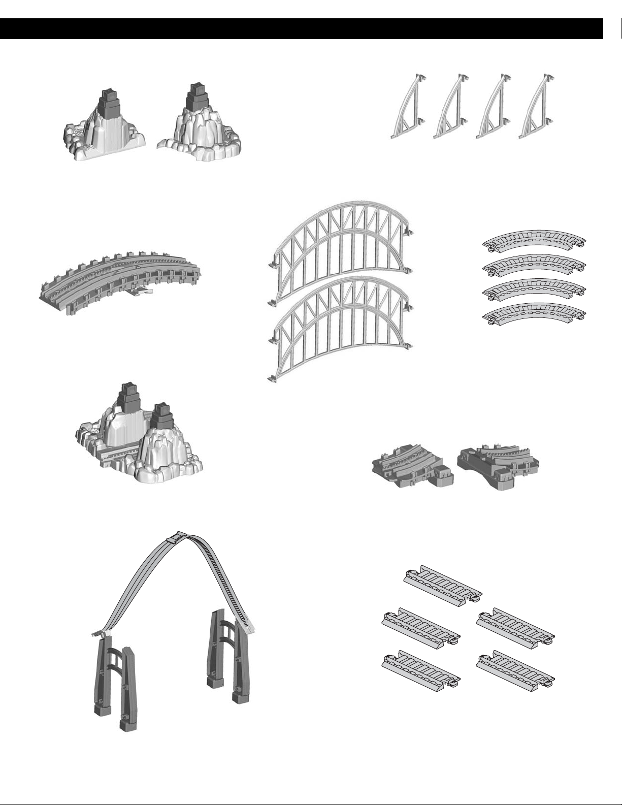
2 Small Bridge Bases
Long Bridge Track
4 End Rails
4 Curved Tracks
2 Side Rails
Large Bridge Base
Bridge Arches
with Air Track
2 Short Bridge
Tracks
5 Straight Tracks
3
Page 4
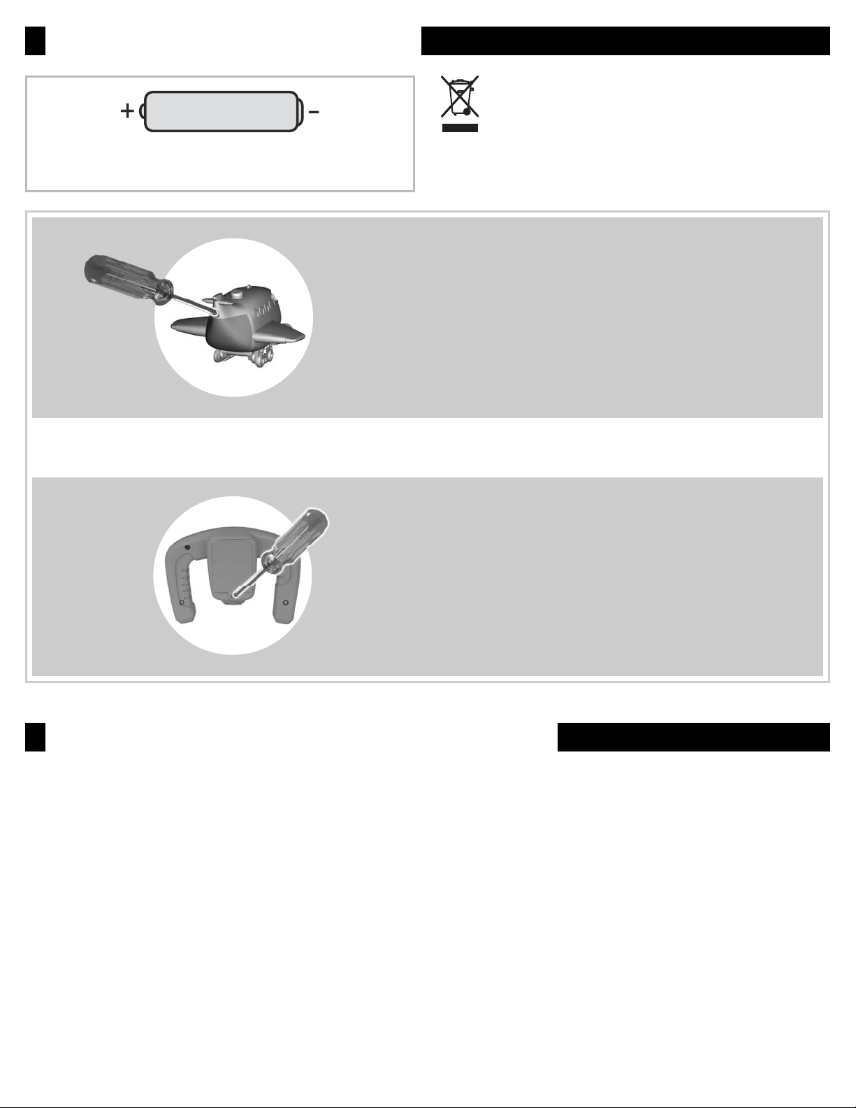
Battery Installation
Protect the environment by not disposing of this product
1,5V x 6
“AAA” (LR03)
We recommend the use of alkaline batteries for
longer battery life.
Airplane
•
•
•
IMPORTANT! Under normal use conditions, the batteries in the vehicle will require replacement more often than the batteries in the
remote controller.
with household waste (2002/96/EC). Check your local
authority for recycling advice and facilities (Europe only).
Locate the battery compartment on the back of the airplane.
Loosen the screw in the battery compartment door with
a Phillips screwdriver. Lower the battery compartment door
and insert three “AAA” (LR03) alkaline batteries.
Close the battery compartment door and tighten the screw
with a Phillips screwdriver. Do not over-tighten.
Remote Controller
Locate the battery compartment on the bottom of the
•
remote controller.
Loosen the screw in the battery compartment door with
•
a Phillips screwdriver. Remove the battery compartment door
and insert three “AAA” (LR03) alkaline batteries.
Replace the battery compartment door and tighten the screw
•
with a Phillips screwdriver. Do not over-tighten.
Battery Safety Information
In exceptional circumstances, batteries may leak fluids that can cause a chemical burn injury or ruin your product. To avoid battery leakage:
• Do not mix old and new batteries or batteries of different types: alkaline, standard (carbon-zinc) or rechargeable (nickel-cadmium).
• Insert batteries as indicated inside the battery compartment.
• Remove batteries during long periods of non-use. Always remove exhausted batteries from the product. Dispose of batteries safely.
Do not dispose of this product in a fire. The batteries inside may explode or leak.
• Never short-circuit the battery terminals.
• Use only batteries of the same or equivalent type as recommended.
• Do not charge non-rechargeable batteries.
• Remove rechargeable batteries from the product before charging.
• If removable, rechargeable batteries are used, they are only to be charged under adult supervision.
4
Page 5

Care
Wipe the toy with a clean, damp cloth. Do not immerse. Do not drop this toy on a hard surface.
•
This toy has no consumer serviceable parts. Do not take this toy apart.
•
Troubleshooting
SYMPTOM SOLUTION
Airplane does not
respond to the
remote controller
Airplane moves slowly
Battery power in the remote controller may be weak. Replace all three batteries in the remote controller
with fresh, alkaline batteries.
You may be beyond the maximum range of the remote controller which is about 12 feet.
You may not have a clear path between the remote controller and the airplane. This toy works best
when there are no obstructions between the airplane and the remote controller.
Bright sunlight or fl uorescent lights may affect the range of the remote controller. Try dimming the room
you are playing in.
The airplane may have shut off. If you do not operate the remote controller for a few minutes, the airplane
shuts off automatically and the ready light turns off. Press the ready button on the airplane, and operate
the remote controller to restart.
Battery power in the airplane may be weak. Replace all three batteries in the vehicle with fresh,
alkaline batteries.
The wheels on the airplane may be dirty. Wipe them with a clean cloth.
FCC Statement
(United States Only)
This equipment has been tested and found to comply with the limits for a Class B digital device, pursuant to Part 15 of the FCC Rules.
These limits are designed to provide reasonable protection against harmful interference in a residential installation. This equipment
generates, uses and can radiate radio frequency energy and, if not installed and used in accordance with the instructions, may cause
harmful interference to radio communications. However, there is no guarantee that interference will not occur in a particular installation.
If this equipment does cause harmful interference to radio or television reception, which can be determined by turning the equipment off
and on, the user is encouraged to try to correct the interference by one or more of the following measures:
Reorient or relocate the receiving antenna.
•
Increase the separation between the equipment and receiver.
•
Consult the dealer or an experienced radio/TV technician for help.
•
Note: Changes or modifi cations not expressly approved by the manufacturer responsible for compliance could void the user's authority to
operate the equipment.
This device complies with Part 15 of the FCC Rules.
Operation is subject to the following two conditions: (1) this device may not cause harmful interference and (2) this device must accept any
interference received, including interference that may cause undesired operation.
ICES-003
This Class B digital apparatus complies with Canadian ICES-003. Operation is subject to the following two conditions: (1) this device
may not cause harmful interference and (2) this device must accept any interference received, including interference that may cause
undesired operation.
5
Page 6

Trestle Assembly
Trestle Base
Trestle Post
Assembly
Main Tower
Terminal Base
Traffic Control Top
Air Track
with Support
Main Tower
1
Terminal Base
Traffic Control Top
2
• “Snap” the main tower into the terminal base.
Trestle Base
• “Snap” the traffic control top into the main tower.
• “Snap” the free end of the air track into the slots in the
top of the main tower
Air Track
with Support
A
A
B
Trestle Assembly
Trestle Post
5
• Connect the trestle post to the trestle base.
• Lift the terminal base and lower to “snap” onto the trestle
assembly, as shown.
6
• Position the air track with support above the terminal base
assembly.
• First, “snap” the ends of the support into the slots in the
loading station A.
• Then, fit the tabs on the track into the slots in the terminal
base B.
6
Page 7

Security Gate
Security Gate
Loading Station
Track with Tabs
Air Track
with Connector
Air Track
with Connector
Loading Station
3
• “Snap” the security gate into the slots in the terminal base.
4
• Fit the loading station onto the terminal base.
Air Track
with Connector
Air Track
with Connector
Track with Tabs
7
• Fit the track with tabs into the slots in the terminal base
and the trestle assembly. Push down to “snap” in place.
8
• Fit an air track with connector onto each end of the traffic
control top tracks.
7
Page 8

Assembly
2 Barn Walls
Barn Base
9
• Fit the barn walls onto the barn base.
• Push down on each wall to “snap” in place.
Hint: Each wall will only fit on the base one way. If a wall
does not seem to fit, try the other wall.
Windows
Roof
Doors
10
• Fit the roof onto the barn walls.
Hint: The windows on the roof should be above the
barn doors.
Short Bridge
Track
Large Bridge Base
13
• “Snap” a short bridge track onto the large bridge base,
as shown.
Short Bridge
Track
Small Bridge Bases
14
• Position the small bridge bases next to each other,
as shown. Make sure the flat side of each base faces
each other.
• “Snap” the other short bridge track onto the small bridge
bases, as shown.
8
Page 9

Air
Track
Windmill
Smokestack
B
A
11
• “Snap” the windmill into the roof A.
Hint: The windmill will only fit in the roof one way. If it does
not seem to fit, turn it around and try again.
• The ends of the track must face opposite directions. Twist
the track and then insert and “snap” the smokestack into
the roof B.
C
Air Track
with Connector
D
Air Track
Connector
B
A
12
• First, connect an air track to one end of the air
track connector inside the barn A.
• Attach the free end of the air track to the connector on
the windmill B.
• Connect an air track to the air track connector on the
smokestack C.
• Then, connect an air track with connector to the air track
connector inside the barn D.
Air Track
Long Bridge
Track
15
• “Snap” the long bridge track onto the bridge
base assemblies.
Air Track
Connector
Arch
Side Rails
16
• “Snap” the ends of both side rails into the arches,
as shown.
Note: The air track needs to form the configuration shown.
Turn the air track connectors to adjust the air track.
Air Track
Connector
Arch
9
Page 10

Assembly
17
• “Snap” the bridge assembly onto the base assembly.
Bridge
Assembly
Base
Assembly
End Rails
End Rails
18
• “Snap” two end rails to each arch, as shown.
20
• Connect the free ends of the air tracks, as shown.
21
• Curved and straight track pieces snap together easily.
10
Page 11

Air Track
Ready Button
Go
Button
Stop
Button
C
A
Connector
B
Air Track
Up, up and away!
Fit the airplane onto the track.
•
Press the ready button on top of the airplane to turn it on.
•
It’s ready for take-off!
Press the go button on the remote controller to start
•
the airplane.
Press the stop button on the remote controller to stop
•
the airplane.
Note: The airplane will go into sleep mode after fi ve
minutes of inactivity. Press the ready button on top of the
airplane to wake it up. Then press the go button on the
remote controller to start the airplane.
•
This toy works best if you have a clear path between
the remote controller and the vehicle. Point the remote
controller at the airplane. The maximum range of the
remote controller is about 12 feet.
Air Track
Connector
Air Track
with Connector
19
• Attach an air track with connector to the air track
connector under the bridge A.
• Next, on the same side of the bridge, attach an air track to
the connector on the arch B.
• Then, on the other side of the bridge, attach an air track to
the connector under the bridge (not shown in illustration)
and the arch C.
Ready Button
Go
Button
Stop
Button
11
Page 12

Please keep this instruction sheet for future reference, as it contains important information.
Requires six “AAA” (LR03) (not included) for operation.
Adult assembly is required.
Tool required for battery installation: Phillips screwdriver (not included).
Visit www.fisher-price.com
to see the entire world
®
of GeoTrax
accessories!
Fisher-Price, Inc., a subsidiary of Mattel, Inc., East Aurora, NY 14052 U.S.A.
©2008 Mattel, Inc. All Right Reserved. ® and ™ designate U.S. trademarks of Mattel, Inc.
PRINTED IN CHINA N9993pr-0920
12
 Loading...