

Page 1
Model T4444
Model M7596
www.fi sher-price.com
Page 2
2
Consumer Information
Consumer Information
WARNING
To avoid serious injury:
• Adult supervision required.
• Never use near cars and other motor
vehicles, near streets, steps,
slopeddriveways, hills, roadways, alleys,
swimming pools or other bodies of water.
• Always wear shoes.
• Never allow more than one rider.
CAUTION
This product contains small parts
in its unassembled state.
Adult assembly is required.
• Please keep this instruction sheet for future reference, as it
contains important information.
• Adult assembly is required.
• Tools needed for assembly: Phillips screwdriver and hammer
(tools not included).
• Requires three, “AAA” (LR03) alkaline batteries for sounds and
lights box operation (not included).
• For children ages 1 1/2 - 5 years.
• Weight limit: 55 lbs (25kg).
• This product is intended for use on smooth, paved surfaces,
away from motor vehicles.
Care
• Periodically check plastic parts and if broken or cracked,
dispose of them properly. Periodically check all fasteners
regularly to be sure they are tight. If the fasteners are not
tight, tighten them as necessary.
• To clean, use a mild soap and water solution and a clean
cloth. Rinse clean with water to remove soap residue.
FCC Statement (United States Only)
This equipment has been tested and found to comply with
the limits for a Class B digital device, pursuant to Part
15 of the FCC Rules. These limits are designed to provide
reasonable protection against harmful interference in a
residential installation. This equipment generates, uses and
can radiate radio frequency energy and, if not installed and
used in accordance with the instructions, may cause harmful
interference to radio communications. However, there is
no guarantee that interference will not occur in a particular
installation. If this equipment does cause harmful interference
to radio or television reception, which can be determined by
turning the equipment off and on, the user is encouraged to
try to correct the interference by one or more of the
following measures:
• Reorient or relocate the receiving antenna.
• Increase the separation between the equipment
and receiver.
• Consult the dealer or an experienced radio/TV technician
for help.
Note: Changes or modifications not expressly approved by the
manufacturer responsible for compliance could void the user's
authority to operate the equipment.
This device complies with Part 15 of the FCC Rules. Operation is
subject to the following two conditions: (1) this device may not
cause harmful interference and (2) this device must accept any
interference received, including interference that may cause
undesired operation.
ICES-003
• This Class B digital apparatus complies with Canadian
ICES-003.
• Operation is subject to the following two conditions: (1) this
device may not cause harmful interference and (2) this
device must accept any interference received, including
interference that may cause undesired operation.
NMB-003
• Cet appareil numérique de la classe B est conforme à la
norme NMB-003 du Canada.
• L’utilisation de ce dispositif est autorisée seulement aux
conditions suivantes: (1) il ne doit pas produire de brouillage
et (2) l’utilisateur du dispositif doit être prêt à accepter tout
brouillage radioélectrique reçu, même si ce brouillage est
susceptible de compromettre le fonctionnement du dispositif.
2
Page 3
3
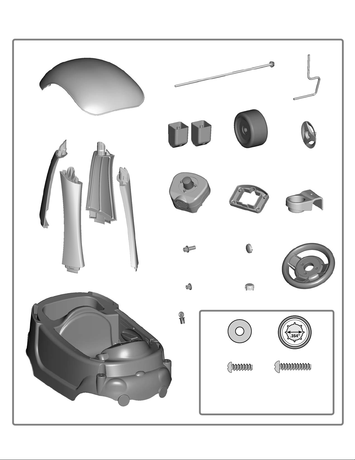
Assembled Parts
Roof
3
16
1
Assembled Parts
Note: Label sheet not shown.
Rear Axle
2 Front Axles
4 Roof Posts
2 Axle Mounts
2 Rear Bushings
2 Front Bushings
RetainerSounds and Lights Box
4 Wheel Covers
2 Cap Nut Covers
4 Hubcaps4 Wheels
Cup Holder
Steering Wheel
Frame
3
Key
/
16
” Washer – 4
#6 x
/2” Screw – 3
ALL SHOWN ACTUAL SIZE
Note: Tighten and loosen all screws with a Phillips screwdriver.
For your convenience, we’ve included extra cap nuts!
Do not over-tighten the screws.
.354” Cap Nuts – 5
#8 x 3/4” Screw – 11
Page 4
4
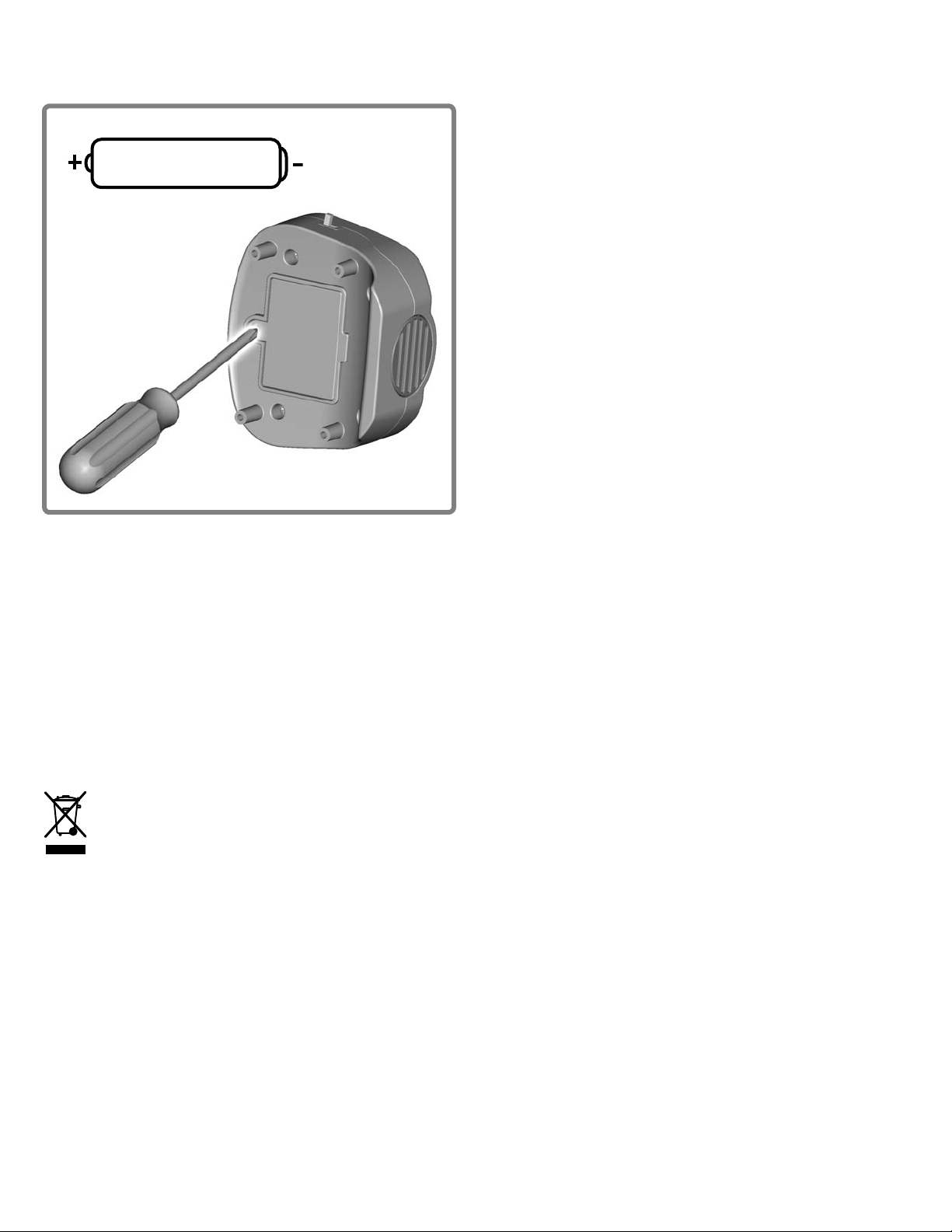
Battery Installation
Battery Installation
Battery Safety Information
1,5V x 3
“AAA” (LR03)
Battery Safety Information
In exceptional circumstances, batteries may leak fluids that can
cause a chemical burn injury or ruin your product. To avoid
battery leakage:
• Do not mix old and new batteries or batteries of different
types: alkaline, standard (carbon-zinc) or rechargeable
(nickel-cadmium).
• Insert batteries as indicated inside the battery compartment.
• Remove batteries during long periods of non-use. Always
remove exhausted batteries from the product. Dispose of
batteries safely. Do not dispose of product in a fire.
The batteries inside may explode or leak.
• Never short-circuit the battery terminals.
• Use only batteries of the same or equivalent type,
as recommended.
• Do not charge non-rechargeable batteries.
• Remove rechargeable batteries from the product
before charging.
• If removable, rechargeable batteries are used, they are
only to be charged under adult supervision.
• Locate the battery compartment on the bottom of the sounds
and lights box.
• Loosen the screw in the battery compartment door. Remove
the battery compartment door.
• Insert three “AAA” (LR03) alkaline batteries.
Hint: We recommend using alkaline batteries for longer
battery life.
• Replace the battery compartment door and tighten the screw
with a Phillips screwdriver. Do not over-tighten.
• If the toy begins to operate erratically, you may need to reset
the electronics. Remove and replace the batteries inside the
battery compartment.
• When sounds or lights from this toy become faint or stop, it’s
time for an adult to change the batteries.
Protect the environment by not disposing of this
product with household waste (2002/96/EC).
Check your local authority for recycling advice
and facilities (Europe only).
4
Page 5

5
Assembly
Sounds
1
16
3
16
Retainer
Sounds and
Lights Box
Lights
Assembly
2
Front
Bushing
”
/
16
Washer
2
Front Axle
Frame
BOTTOM VIEW
• Turn the frame on its side.
• Fit the sounds and lights box onto the dash on the topside of
the vehicle.
• Then, fit the retainer over the battery compartment door on the
underside of the frame. Insert four #8 x 3/4” screws into the retainer
and tighten.
• Turn the frame upright.
3
Wheel
Hubcap
Front Axle
• Slide a 3/
• Then, slide a front bushing, flat side first, onto the front axle.
16”
washer onto the front axle labeled 2.
4
Cap Nut
• Slide a wheel, smooth side first, onto the front axle.
• Then, slide a hubcap, post side first, onto the front axle and into
the wheel.
Wheel
Cover
• Fit a cap nut onto the end of the front axle.
• Tap the cap nut with a hammer. Gently pull the wheel to make
sure the cap nut is securely attached to the front axle.
• Fit a wheel cover onto the hubcap, and push to “snap” in place.
5
Page 6

6
16
16
3
16
Assembly
Assembly
Ax
5 6
Cap Nut
Frame Front End
2
”
/
16
Washer
Front Axle
FRONT VIEW
• First, slide a 3/
• Then, insert the front axle labeled 2 up through the hole in the
front end of the frame also labeled 2.
16” washer onto the front axle.
Rear Bushing
9
Wheel
Hubcap
Front Axle
• Fit a cap nut onto the end of the front axle, as shown.
• Tap the cap nut with a hammer.
• Gently pull the front wheel down to be sure the cap nut is
securely attached to the front axle.
• Repeat assembly steps 2-6 to assemble the front axle labeled 1,
a wheel, a front bushing, a 3/
wheel cover.
16” washer, two cap nuts and a
Axle Mounts
10
Rear Axle
Rear Axle
• Slide a hubcap, post side up, onto the rear axle.
• Next, slide a wheel, smooth side up, onto the rear axle.
• Then, slide a rear bushing, short end down, onto the rear axle.
• Slide the rear axle through the holes in the axle mounts.
6
Page 7

7
Rear Bu
Assembly
Assembly
7 8
• Fit a cap nut cover over each cap nut on the front end of the
frame. Push to “snap” in place.
Cap Nut Covers
Axle Mount
BOTTOM VIEW
• Turn the frame upside down on a flat surface.
• Fit an axle mount onto the pegs near the rear of the frame.
Hint: Each axle mount only fits on one side of the vehicle. If it does
not line up with the pegs on the frame, try fitting it to the other side.
• Insert three #8 x ¾” screws into the axle mount and tighten.
• Repeat this procedure to assemble the other axle mount to the
rear of the frame.
11
Rear Bushing
Hubcap
• Slide a rear bushing, long end first, onto the rear axle.
• Next, slide a wheel, smooth side first, onto the rear axle.
• Then, slide a hubcap, post side first, onto the rear axle.
Wheel
12
Cap
Nut
• Fit a cap nut onto the end of the rear axle.
• Tap the cap nut with a hammer. Gently pull the wheel to make
sure the cap nut is securely attached to the rear axle.
Hint: You may need the help of another adult to hold the rear axle
in place while you tap the cap nut.
7
Page 8

8
Cap Nut Cover
Assembly
Assembly
13
• Fit a cap nut cover onto each rear wheel and push to “snap”
in place.
14
Steering Wheel
Sounds and
Lights Box
• Turn the frame upright.
• Fit the steering wheel onto the sounds and lights box.
• Insert three #6 x ½” screws into the steering wheel and tighten.
17
Roof Assembly
• Fit the roof assembly onto the frame. Push near each post to
“snap” in place.
Hint: The roof assembly is designed to only fit one way. If it does
not seem to fit turn it around and try again.
18
Cup
Holder
• Fit the cup holder onto the side of the frame.
• Insert a #8 x ¾” screw into the cup holder and tighten.
8
Page 9

9
Assembly
Assembly
15
Key
• Fit the key into the hole in the dash. Push to “snap” in place.
Posts
16
Roof
• Turn the roof upside down on a flat surface.
• Fit the four posts into the roof and push to “snap” in place.
Hint: Each post is labeled (1, 2, 3 or 4). Match the number on the
post to the number on the roof.
9
Page 10

10
Decoration
Decoration
• Before applying the labels, wipe the surface of the vehicle with
a clean, dry cloth to remove any dust or oils.
• Place the labels exactly as shown in the illustrations. For best
results, avoid repositioning a label once it has been applied to
the vehicle.
• After applying a label, rub the label firmly with a clean, dry
cloth to make sure the label is adhered to your vehicle. Start at
the center of a label, and smooth towards the outer edges to
remove air bubbles.
2
5
(M7596 Only)6(T4444 Only)
5
(T4444 only)5(M7596 Only)
1
FRONT VIEW
7
(T4444 Only)
4
(T4444 Only)
6
(M7596 Only)
1
9
10
(T4444 Only)
10
3
BACK VIEW
7
(M7596 Only)
8
(T4444 Only)
Page 11

11
Use
Use
Press the horn on the steering wheel
for fun car songs and lights!
Real working door!
11
Page 12

PRINTED IN MEXICO M7596a-0920
CONSU
MER
ASSISTANC
1-800-432-5437 (US & Canada)
1300 135 312 (Australia)
Fisher-Price, Inc., 636 Girard Avenue, East Aurora, NY 14052.
Hearing-impaired consumers: 1-800-382-7470.
Outside the United States:
Canada: Mattel Canada Inc., 6155 Freemont Blvd.,
Mississauga, Ontario L5R 3W2; www.service.mattel.com.
Great Britain: Mattel UK Ltd, Vanwall Business Park,
Maidenhead SL6 4UB. Helpline: 01628 500303.
www.service.mattel.com/uk
Mattel Europa, B.V., Gondel 1, 1186 MJ Amstelveen, Nederland.
Australia: Mattel Australia Pty. Ltd., 658 Church Street,
Locked Bag #870, Richmond, Victoria 3121 Australia.
New Zealand: 16-18 William Pickering Drive,
Albany 1331, Auckland.
E
Fisher-Price, Inc., a subsidiary of Mattel, Inc., East Aurora, New York 14052 U.S.A.
©2010 Mattel, Inc. All Rights Reserved. ® and ™ designate U.S. trademarks of Mattel, Inc.
PRINTED IN MEXICO M7596a-0920
 Loading...