

Page 1

www.fisher-price.com
K8378
2
Page 2

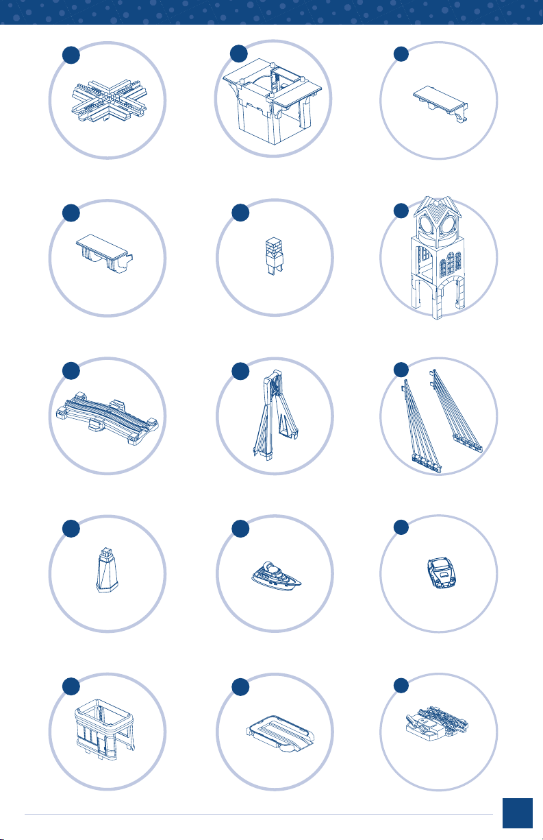
Parts
A. Clock Tower Cross Track
B. Clock Tower Base
C. 2 Arched Overhangs
D. 2 Plain Overhangs
E. Chimney
F. Tower
G. Span
H. Arch
I. Cable Structures
J. 4 Bridge Supports
K. Boat
L. Sports Car
M. Gas Station Building
N. Gas Station Base
O. Base Extension
P. Gas Station Roof
Q. Pump
R. Gas Station Sign
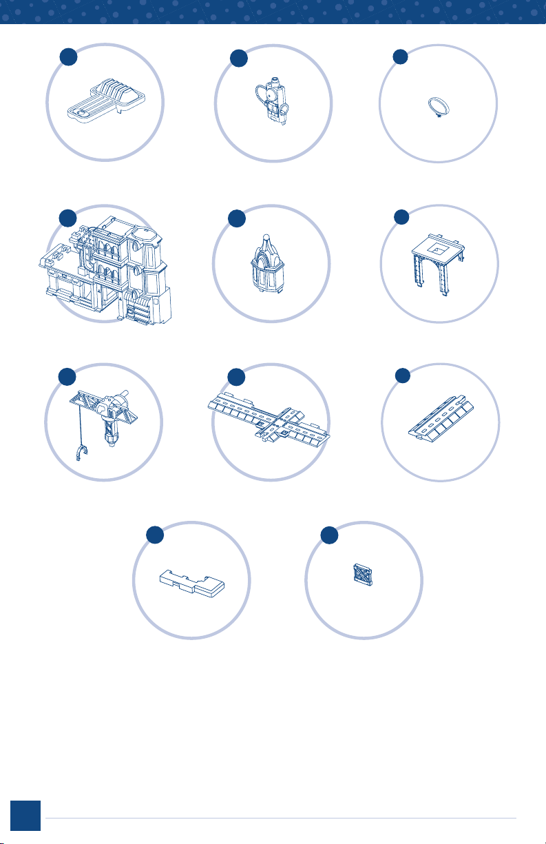
S. Main Assembly
T. Buildling Top
U. City Arch
V. Crane
W. T-Track
X. City Keyed Track
Y. Curb
Z. 4 Building Pieces
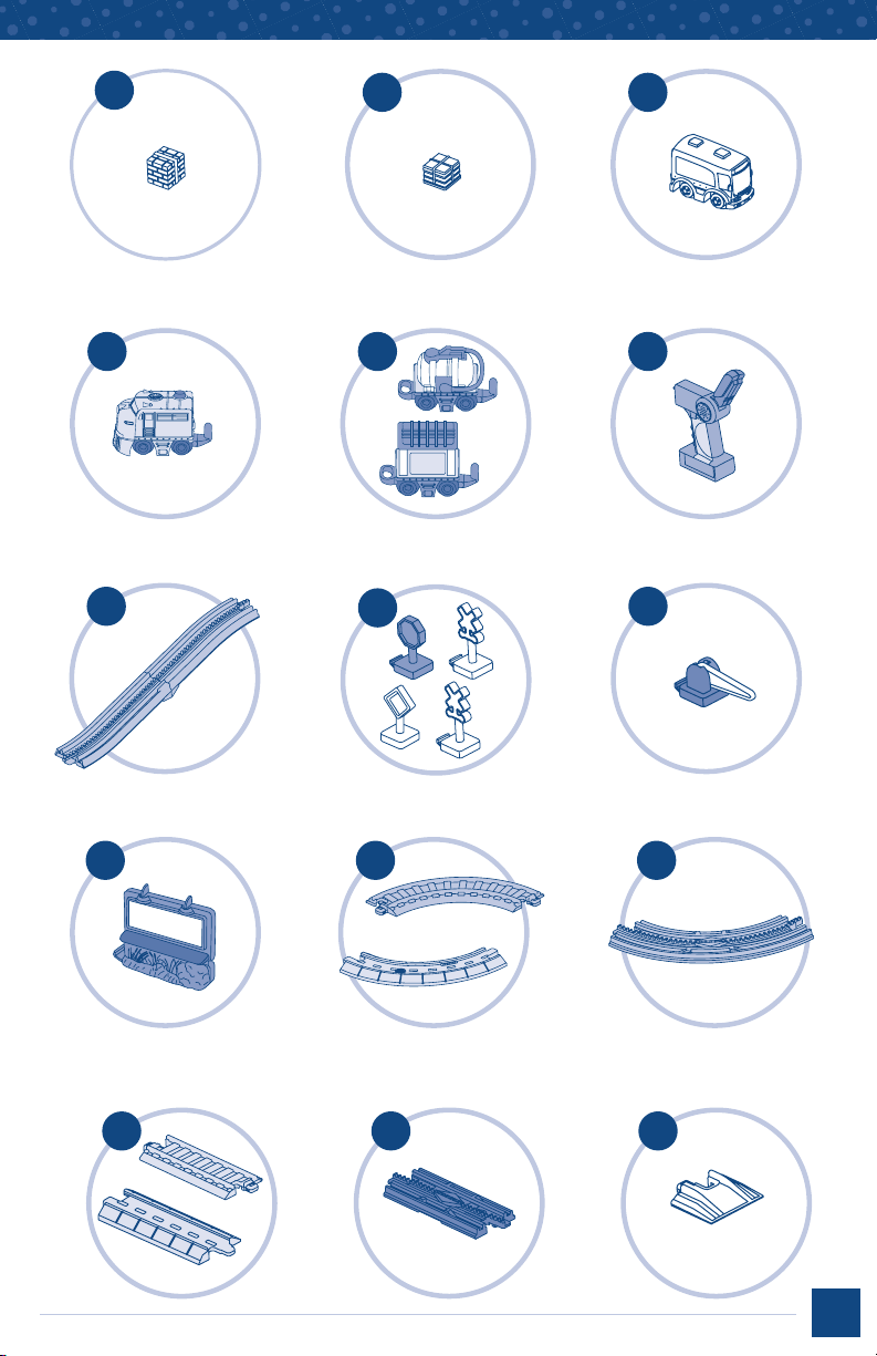
AA. Brick Stack
BB. Newspaper Stack
CC. Bus
DD. RC Train Engine
EE. 2 Train Cars
FF. Remote Controller
GG. 2 Ramp Assemblies
HH. 4 Signs
II. Crossing Gate
JJ. Billboard
KK. 4 Curved Tracks
LL. 2 Elevated Curved Tracks
MM. 4 Straight Tracks
NN. 1 Elevated Straight Track
OO. 2 Short Ramps
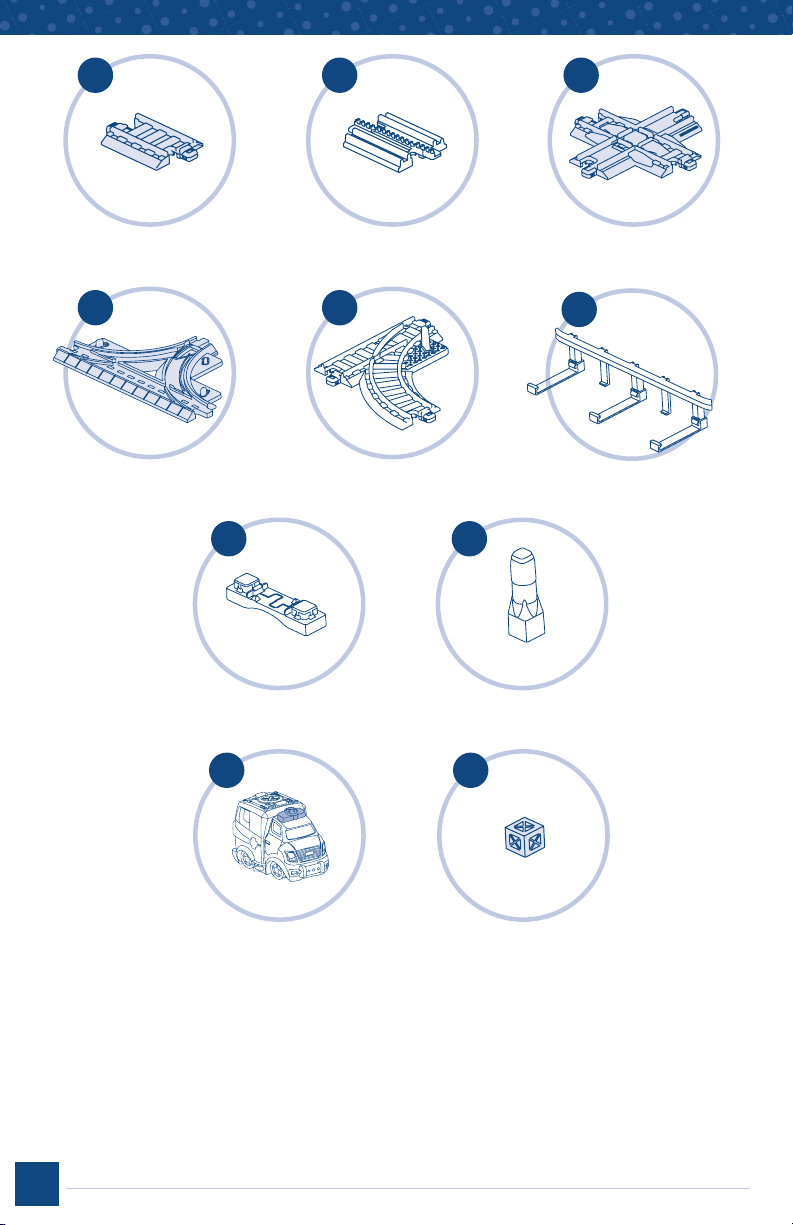
PP. 2 Small Tracks
QQ. 1 Elevated Short Track
RR. Cross Track
SS. Double Curve Track
TT. 1 Turn Off Track
UU. 2 Guard Rails
VV. 2 Support Tops
WW. 4 Support Columns
XX. Ambulance
YY. Crate
Please keep this instruction sheet for future reference, as it contains important information.
Requires 14 “AAA” (LR03)
Adult assembly is required.
Tool required for battery installation: Phillips screwdriver (not included).
alkaline and 3 “AA” (LR6) alkaline batteries (not included).
2
Page 3
A
B
C
x2
D
G
E
F
x2
H
J
K
I
x2
x2
L
M
x4
N
O
3
Page 4
P
Q
R
S
V
Y
T
W
Z
U
X
x4
4
Page 5
AA
BB
CC
DD
GG
JJ
x2
EE
HH
KK
FF
I I
LL
x2
MM
x2
x2
NN
x2
x2
OO
x2
5
Page 6
PP
x2
QQ
RR
SS
VV
XX
x2
TT
UU
x2
WW
x4
YY
6
Page 7
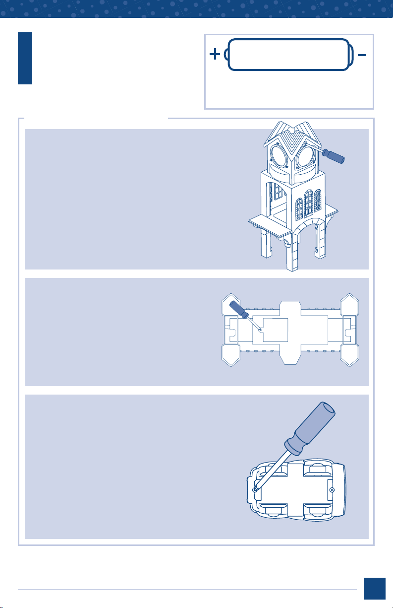
Battery
1.5V x 14
“AAA” (LR03)
Information
Battery Installation
Clock Tower
• Locate the battery compartment on the
clock tower.
• Loosen the screw in the battery compartment
door with a Phillips screwdriver. Remove the
battery compartment door.
• Insert three “AAA” (LR03) alkaline batteries.
• Replace the battery compartment door and
tighten the screw with a Phillips screwdriver.
Do not over-tighten.
• When sounds from this toy become faint or stop,
it’s time for an adult to change the batteries.
Bridge
• Locate the battery compartment on the
underside of the span.
• Loosen the screw in the battery compartment
door with a Phillips screwdriver. Remove the
battery compartment door.
• Insert four “AAA” (LR03)
• Replace the battery compartment door and
tighten the screw with a Phillips screwdriver.
alkaline batteries.
SHOWN ACTUAL SIZE
We recommend the use of alkaline batteries
for longer battery life.
Ambulance
• Loosen the screw in the battery compartment
door with a Phillips screwdriver. Remove
the battery compartment door. Remove the
exhausted battery and throw it away.
• Insert a “AAA” (LR03)
Hint: We recommend using an alkaline battery
for longer battery life.
• Replace the battery compartment door and
tighten the screw with a Phillips screwdriver.
Do not over-tighten.
• When sounds or lights become faint or stop,
it’s time for an adult to change the batteries!
alkaline battery.
7
Page 8
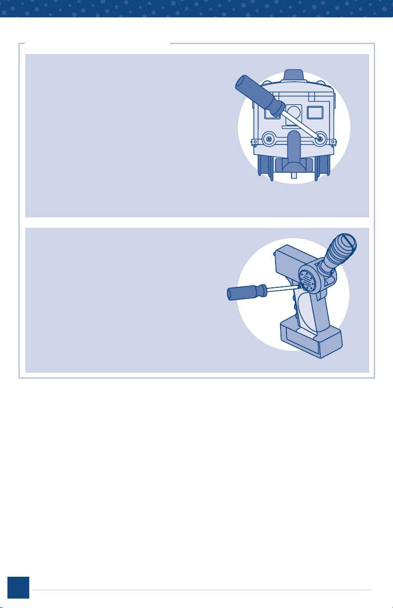
Battery Installation
Train Engine
• Locate the battery compartment on the back of
the train engine.
• Loosen the screws in the battery compartment
door with a Phillips screwdriver. Lift the battery
compartment door and insert three “AAA” (LR03)
alkaline batteries.
• Close the battery compartment door and tighten
the screws with a Phillips screwdriver. Do not
over-tighten.
IMPORTANT! Under normal conditions, the batterie
s in the engine will require replacement more
often than the batteries in the remote controller.
For additional information, see the troubleshooting
section.
Remote Controller
• Locate the battery compartment on the side
of the remote controller.
• Loosen the screw in the battery compartment
door with a Phillips screwdriver. Remove the
battery compartment door and insert three
“AAA” (LR03)
• Replace the battery compartment door and
tighten the screw with a Phillips screwdriver.
Do not over-tighten.
• When the train does not respond to the remote
controller, it's time for an adult to change the
batteries in the remote controller.
alkaline batteries.
8
Page 9
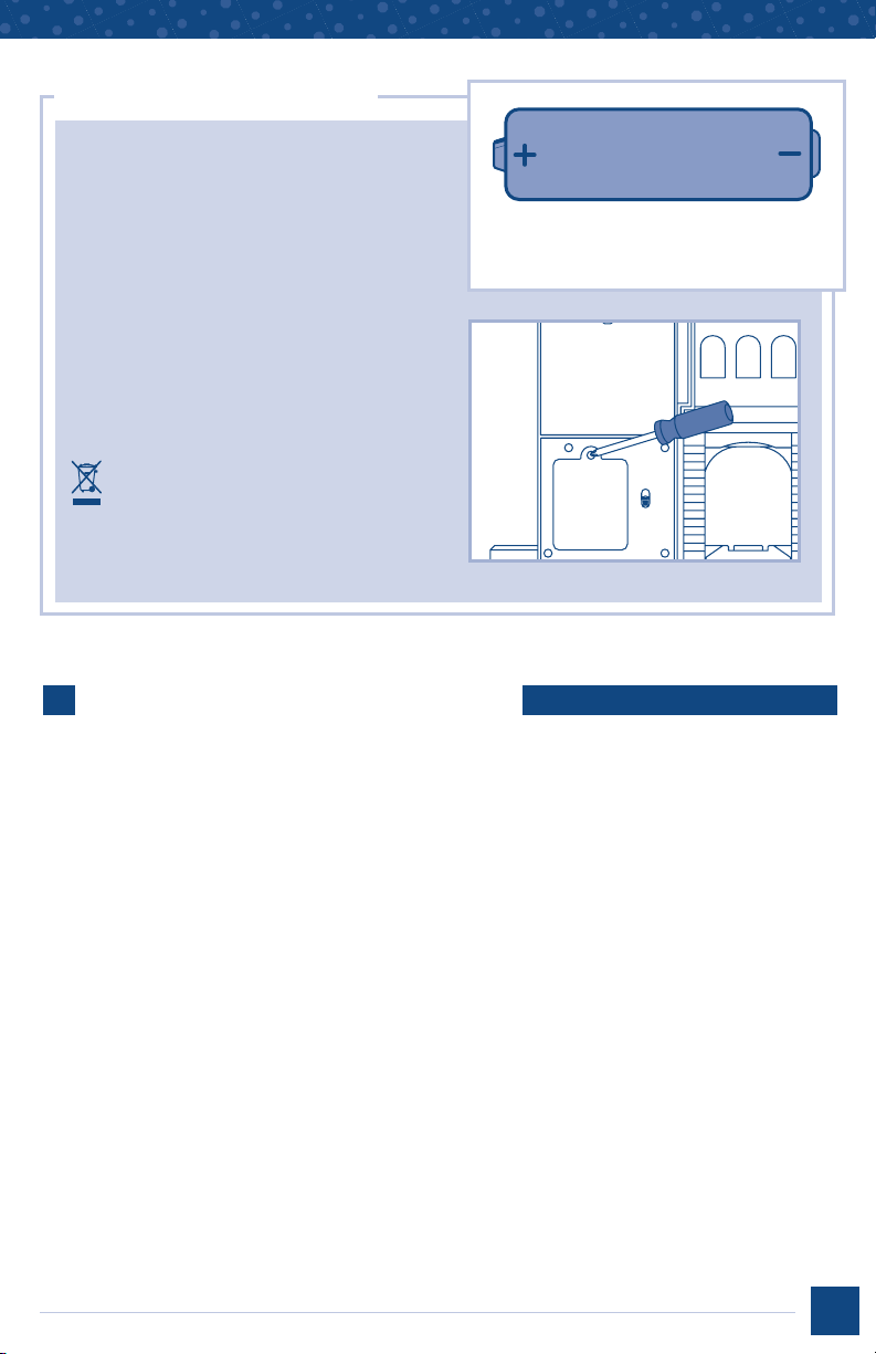
Battery Installation
City
• Locate the battery compartment on
the back of the main assembly.
• Loosen the screw in the battery
compartment door with a Phillips
screwdriver. Remove the battery
compartment door.
• Insert three “AA” (LR6)
• Replace the battery compartment door and
tighten the screw with a Phillips screwdriver.
Do not over-tighten.
• When sounds or lights become faint
or stop, it’s time for an adult to change
the batteries.
• Protect the environment by not
disposing of this product with
household waste (2002/96/EC).
Check your local authority for
recycling advice and facilities
(Europe only).
alkaline batteries.
Battery Safety Information
1.5V x 3
“AA” (LR6)
SHOWN ACTUAL SIZE
We recommend the use of alkaline batteries
for longer battery life.
In exceptional circumstances, batteries may leak fluids that can cause a chemical burn
injury or ruin your toy. To avoid battery leakage:
• Do not mix old and new batteries or batteries of different types: alkaline, standard
(carbon-zinc) or rechargeable (nickel-cadmium).
• Insert batteries as indicated inside the battery compartment.
• Remove batteries during long periods of non-use. Always remove exhausted batteries from
the toy. Dispose of batteries safely. Do not dispose of the product in a fire. The batteries
inside may explode or leak.
• Never short-circuit the battery terminals.
• Use only batteries of the same or equivalent type, as recommended.
• Do not charge non-rechargeable batteries.
• Remove rechargeable batteries from the toy before charging.
• If removable, rechargeable batteries are used, they are only to be charged under
adult supervision.
9
Page 10

Assembly - Bridge
“Snap” the arch onto the span.
1
3
ARCH
SPAN
“Snap” a cable structure
to the side of the span.
2
10
• “Snap” the top of the cable structure to
the top of the arch.
• Repeat this procedure to attach the other
three cable structures to the span.
Note: Each cable structure assembles to
the span one way!
4
“Snap” the four bridge
supports to the underside
of the span.
Bridge assembly is now complete!
Page 11

Assembly-Gas Station
• "Snap" the gas station building
1
• "Snap" the gas station base on
to the base extension.
3
to the gas station base.
2
• "Snap" the gas station roof onto the top
of the gas station building and pump.
• "Snap" the gas station sign onto the top
of the pump.
Gas Station assembly is now complete!
• "Snap" the pump into the
base extension.
4
11
Page 12

Assembly-City
MAIN ASSEMBLY
1
CURB
“Snap” the mainassembly
onto the curb.
4
“Snap” the main assembly
on to the track assembly.
2
ARCH
“Snap” the arch to the
main assembly.
3
T-TRACK
KEYED
TRACK
CRANE
BUILDING
TOP
5
“Snap” the building top and
the crane onto the main
assembly.
City assembly is now complete!
12
Fit the T-track onto the keyed
track, as shown.
Page 13

Assembly - Clock Tower
1
CLOCK
TOWER
BASE
“Snap” the clock tower cross
track into the clock tower base.
CLOCK TOWER
CROSS TRACK
2
4
“Snap” the chimney into the
top of the tower.
5
CHIMNEY
PLAIN
OVERHANG
“Snap” the plain overhangs into
the clock tower base, as shown.
ARCHED
OVERHANG
3
“Snap” the arched overhangs
into the tower, as shown.
Place the tower onto the
base assembly.
Clock Tower assembly is now complete!
13
Page 14

Assembly - Support Columns
SUPPORT TOP
“Snap” a support top onto
two support columns.
14
Page 15

Elevation Track Tips
1
You can stack up support
column assemblies to make
a higher track layout.
2
To properly support elevated
tracks, always make sure you
have support columns under
track connections.
3
• When you have a curved track at the bottom of a ramp assembly, be sure to
use a guardrail on the curve. This keeps the fast moving train on the track!
• To attach the guardrail, fit a tab on one end of the guardrail under the curved
track, as shown.
• Bend the guardrail slightly to fit the other two tabs to the curved track.
15
Page 16

Track Layout
Track pieces easily
snap together.
GeoTrax® signs
have a small tab
that fits into a
matching slot on
any track piece.
Place the signs
around the track.
16
17
Page 17

Three Levels of Fun
with the Clock Tower!
• To build a layout on the bottom level, just
place a straight track through the bottom
arch of the tower.
LEVEL
1
• Attach a ramp assembly to the
middle level to reach the ground.
• Use support columns and
straighttracks to build an
elevated assembly.
LEVEL
2
18
LEVEL
3
• Additional support columns (sold
separately with Elevation Track
Packs™) are required to access
the third level of the tower.
• Attach a ramp assembly to a
support column to reach the
third level.
• Use two support columns stacked
up and straight tracks to build an
elevated assembly.
Page 18

All Aboard!
Your child is bound for a world of adventure!
Your child is bound for a world of adventure!
POWER
BUTTON
•
Hook the cars together and place them on
the track. Make sure the engine is in front.
Hint: We do not recommend using the engine
on carpets. For best performance, use on the
track provided or hard,flat surfaces.
3-Position Remote Controller
READY
LIGHT
3
2
1
1
OFF
2
FORWARD
3
FORWARD
(With Sound Effects)
• Press the power button on top of the
engine. The ready light turns on.
• Hold the remote controller with the stick
facing you. Point the remote controller
toward the engine and push the stick
forward. The engine moves forward
around the track.
• To stop the engine, pull the stick
backwards to the stop position.
Hints:
• If you do not operate the remote controller
for a few minutes, the engine shuts off
and the ready light turns off. Press the
engine power button, and operate the
remote controller to restart.
• This toy works best if you have a
clear path between the remote controller
and the engine. Point the remote
controller at the engine. The maximum
range of the remote controller is about
12 feet.
19
Page 19

Drive Through for
a Rainbow of Lights!
PRESS
• Locate the power switch on the underside
of the bridge. Slide the switch to
the toy on.
•
Push the car over the bridge or drive a train
engine
(sold separately) over to see colorful
lights. You can also press the button on the
bridge to see the lights.
•
When you are finished playing with this toy,
slide the power switch off O.
to turn
• Remove the supports to use the bridge
at ground level.
20
Page 20

Chimes & Music!
When a train travels through the middle or top level of the tower, you’ll hear
chimes and music.
PRESS
1
POWER
SWITCH
• Locate the power switch near the
top of the tower.
• Slide the switch to the
to turn the toy on and the
position to turn the toy off.
position
•
°
2
• Press the chimney to
activate the tower.
• When the train goes
through either the
middle level or top
level of the tower,
you’ll hear chimes
and music.
Hint: If the a train does not pass through the clock tower in a few minutes, the tower turns
off automatically and plays a chime. Press the chimney again to turn the tower back on.
Important: The clock tower sound effect feature is activated by contrast in lighting. This
feature may not work if the toy is in very bright light or direct sunlight. Please keep the clock
tower out of bright light or direct sunlight.
21
Page 21

Chimes & Music!
• You do not need an elevated set up to utilize the
tower sound effect feature.
• Separate the tower into two parts, so the middle
level is now at ground level. When a train goes
through this level, you’ll also hear chimes
and music.
• Rotate the spinner
on the tower to
play a song.
SPIN
22
Page 22

Bright Lights and
City Sounds
• Locate the power switch on the back of the toy.
• Slide the switch to
• When you are finished playing with this toy, slide the switch off
• Press the button for brilliant
lights and sounds of the city.
to turn the toy on.
• Turn the crank on the crane
and lift or lower the “bricks.”
• Rotate the crane for more
sounds and lights.
O.
•
Load the “bricks” or
“newspapers” into a train
car (sold separately).
23
Page 23

Exciting Lights
and Sounds
• Press the button on top of the vehicle for exciting
lights and sounds.
FCC Statement
United States Only
This equipment has been tested and found to comply with the limits for a Class B digital
device, pursuant to Part 15 of the FCC Rules. These limits are designed to provide reasonable
protection against harmful interference in a residential installation. This equipment generates,
uses and can radiate radio frequency energy and, if not installed and used in accordance with
the instructions, may cause harmful interference to radio communications. However, there
is no guarantee that interference will not occur in a particular installation. If this equipment
does cause harmful interference to radio or television reception, which can be determined by
turning the equipment off and on, the user is encouraged to try to correct the interference by
one or more of the following measures:
• Reorient or relocate the receiving antenna.
• Increase the separation between the equipment and receiver.
• Consult the dealer or an experienced radio/TV technician for help.
Note: Changes or modifications not expressly approved by the manufacturer responsible for
compliance could void the user’s authority to operate the equipment.
24
Page 24

So Many Ways
™
to Play!
Turn the crank. The sign
rotates, the pump dial
spins and the bell rings.
The Magic of
Flip the GeoMotion™
switch in front
of the gas station.
Slide your vehicle into
the garage bay for
repairs.
Use your remote
controller to drive your
RC engine in front of
the gas station.
Use the hose to "fill up"
your vehicle.
!
GeoMotion™ rotates
the sign and pump dial
and rings the bell.
Flip the GeoMotion
switch back to drive on.
™
GeoTrax® RC vehicle and additional track and play pieces sold separately and subject to availability.
25
Page 25

The more you collect,
the more fun it gets!
Woo-
Woo-
Wooooo!
Use multiple
remote control
vehicles
at once!
Wooooo!
Rhhhh!
Rhhhh!
Toot!
Toot!
Toot!
Toot!
Playsets and accessories sold separately and subject to availability.
26
Page 26

Troubleshooting
SYMPTOM SOLUTION
Engine drives slowly
Engine does not
respond to the
remote controller
Battery power in the engine may be weak. Replace all three batteries
in the engine with fresh, alkaline batteries.
The wheels on the engine or attached cars may be dirty.
Wipe them with a clean cloth.
Battery power in the remote controller may be weak. Replace all
three batteries in the remote controller with fresh, alkaline batteries.
You may be beyond the maximum range of the remote controller
which is about 12 feet.
You may not have a clear path between the remote controller and
the engine. This toy works best when there are no obstructions
between the engine and the remote controller.
Bright sunlight or fluorescent lights may affect the range of the remote
controller. Try dimming the room you are playing in.
The engine may have shut off. If you do not operate the remote
controller for a few minutes, the engine shuts off automatically and
the ready light turns off. Press the power button on the engine, and
operate the remote controller to restart.
27
Page 27

Visit www.fisher-price.com
to see the entire world of
GeoTrax® accessories!
Visit us on-line at www.service.fisher-price.com.
Call our Consumer Relations Department, toll-free at 1-800-432-5437,
9 AM - 7 PM EST Monday through Friday and 11 AM - 5 PM EST Saturday.
Hearing-impaired consumers using TTY/TD equipment, please call 1-800-382-7470.
Write to us at:
Fisher-Price
®
Consumer Relations
636 Girard Avenue, East Aurora, New York 14052
For countries outside the United States:
CANADA: Questions? 1-800-567-7724. Mattel Canada Inc., 6155 Freemont Blvd.,
GREAT BRITAIN: Mattel UK Ltd, Vanwall Business Park, Maidenhead SL6 4UB. Helpline: 01628 500303; www.service.mattel.com/uk.
AUSTRALIA: Mattel Australia Pty. Ltd., 658 Church Street, Locked Bag #870, Richmond, Victoria 3121 Australia.
ASIA: Mattel East Asia Ltd, Room 1106, South Tower, World Finance Centre, Harbour City, Tsimshatsui, HK, China.
Mississauga, Ontario L5R 3W2; www.service.mattel.com.
Consumer Advisory Service 1300 135 312.
NEW ZEALAND: 16-18 William Pickering Drive, Albany 1331, Auckland.
Fisher-Price, Inc., a subsidiary of Mattel, Inc., East Aurora, NY 14052 U.S.A.
©2005 Mattel, Inc. All Right Reserved. ® and ™ designate U.S. trademarks of Mattel, Inc.
PRINTED IN CHINA K8378pr-0920
 Loading...