

Page 1

Keep this instruction sheet for future reference, as it contains important information.
Adult assembly is required.
Tool needed for assembly: Phillips screwdriver (not included).
Hand pump (not included) and inflation pin (not included) required to inflate the soccer ball.
Requires three AAA (LR03) alkaline batteries (not included) for operation.
Please remove all parts from the package and identify them before assembly.
DTM21
B8507
fisher-price.com
Page 2
2
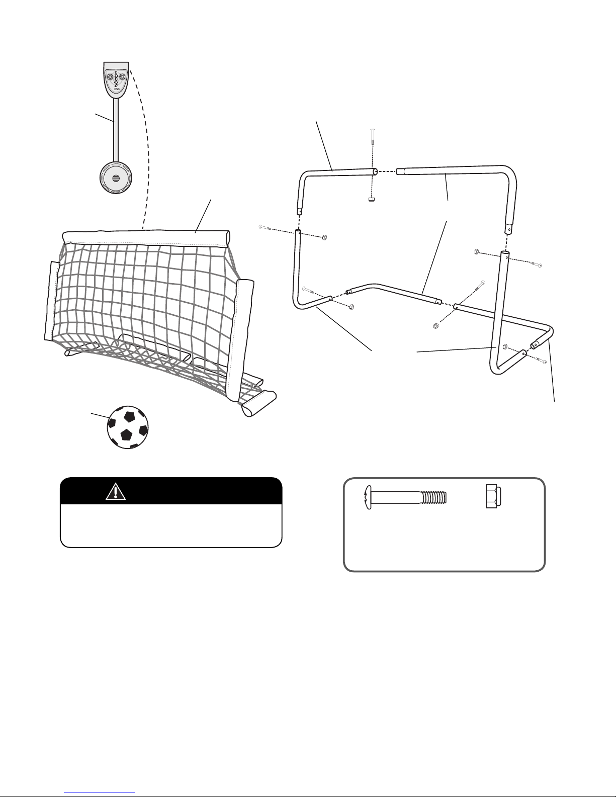
Parts
2 Tubes with Tapered
Ends (Upper and Lower)
Tube with Tapered End and
Regular End (Upper)
2 Side Tubes
Net
Target
Ball
M5 x 28 mm Screw - 6
BOTH SHOWN ACTUAL SIZE
Note: Tighten and loosen all screws with a Phillips
Screwdriver. Do not over-tighten the screws.
M5 Lock Nut - 6
Tube with Tapered End
and Regular End (Lower)
CAUTION
This package contains small parts.
For adult assembly only.
Page 3
3
1
2
3
Assembly
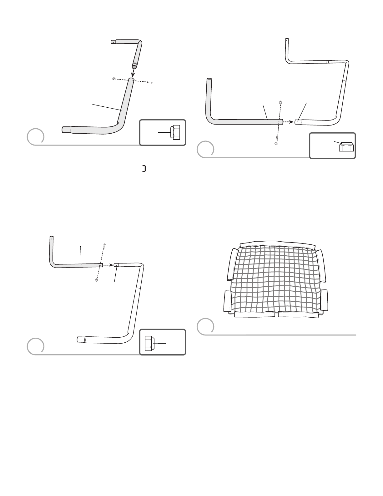
• Place a tube with tapered end and regular end on a flat surface.
• Fit a tube with tapered ends into the regular end, as shown.
Hint: The tube assembly should form this shape .
• Align the holes in the tubes.
• Fit a lock nut, rounded side out, into the hex hole on the inside of
the tube with tapered end and regular end.
• Insert a screw through the outside of the tube with tapered end
and regular end.
• While holding the lock nut in place with your thumb, tighten
the screw.
• Fit the long end of a side tube onto either tapered end of the
assembly.
• Align the holes in the two tubes.
Hint: If the holes in the tubes do not align, remove the side tube
and place it on the other end of the assembly.
• Fit a lock nut, rounded side out, into the hex hole in the inside of
the side tube.
• Insert a screw through the hole on the outside of the side tube.
• While holding the lock nut in place with your thumb, tighten
the screw.
Tapered
End
Side Tube
Long End
• Fit the long end of the other side tube onto the other tapered end
of the assembly.
• Align the holes in the two tubes.
• Fit a lock nut, rounded side out, into the hex hole on the inside of
the side tube.
• Insert a screw through the hole on the outside of the side tube.
• While holding the lock nut in place with your thumb, tighten
the screw.
Tube with Tapered
End and Regular End
Tube with Tapered Ends
Tapered
End
Side Tube
Long End
• Lay the net on a flat surface. Note the locations of the sleeves on
the net.
Bottom Sleeves
Top Sleeve
Side
Sleeve
Side
Sleeve
Short
Sleeve
Short
Sleeve
Rounded
Side
Rounded
Side
Rounded
Side
4
Page 4
4
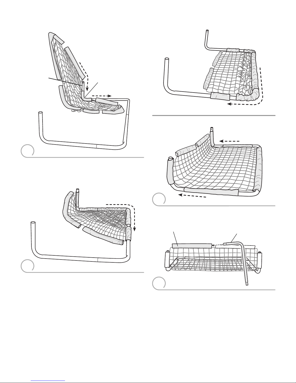
• Fit the short end of either remaining tube through the end of
a bottom sleeve.
Short End of Tube
Bottom Sleeve
• Next, fit the side sleeve, top sleeve, side sleeve and other short
sleeve onto the side tube.
Note: Do not fit the bottom sleeves onto the tube in this assembly step.
• Slide the sleeves and the net evenly around the frame, as shown.
• Locate the short sleeves on the sides of the net.
• Fit a short sleeve onto a side tube.
Note: Do not fit the bottom sleeves onto the tube in this assembly step.
Short Sleeve
Side Tube
Assembly
5
6
7
8
Page 5
5
13
10
Assembly
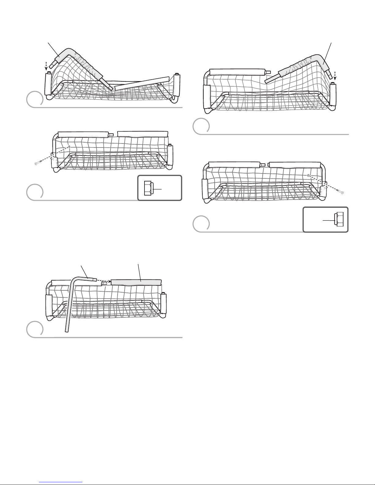
• Fit the short end of the tube into the frame assembly.
Short End of Tube
• Fit the short end of the tube into the frame assembly.
Short End of Tube
• Fit a lock nut, rounded side out, into the hex hole on the inside of
the tube assembly.
Hint You may need to slide the net down to access the hole.
• Insert a screw into the outside hole in the side tube assembly.
• While holding the lock nut in place with your thumb, tighten
the screw.
• Fit a lock nut, rounded side out, into the hex hole on the inside of
the tube assembly.
Hint You may need to slide the net down to access the hole.
• Insert a screw into the outside hole in the side tube assembly.
• While holding the lock nut in place with your thumb, tighten
the screw.
• Fit the short end of the remaining tube through the end of the
bottom sleeve.
Short End of Tube
Bottom Sleeve
Rounded
Side
Rounded
Side
9
11
12
Page 6
6
14
15
Assembly
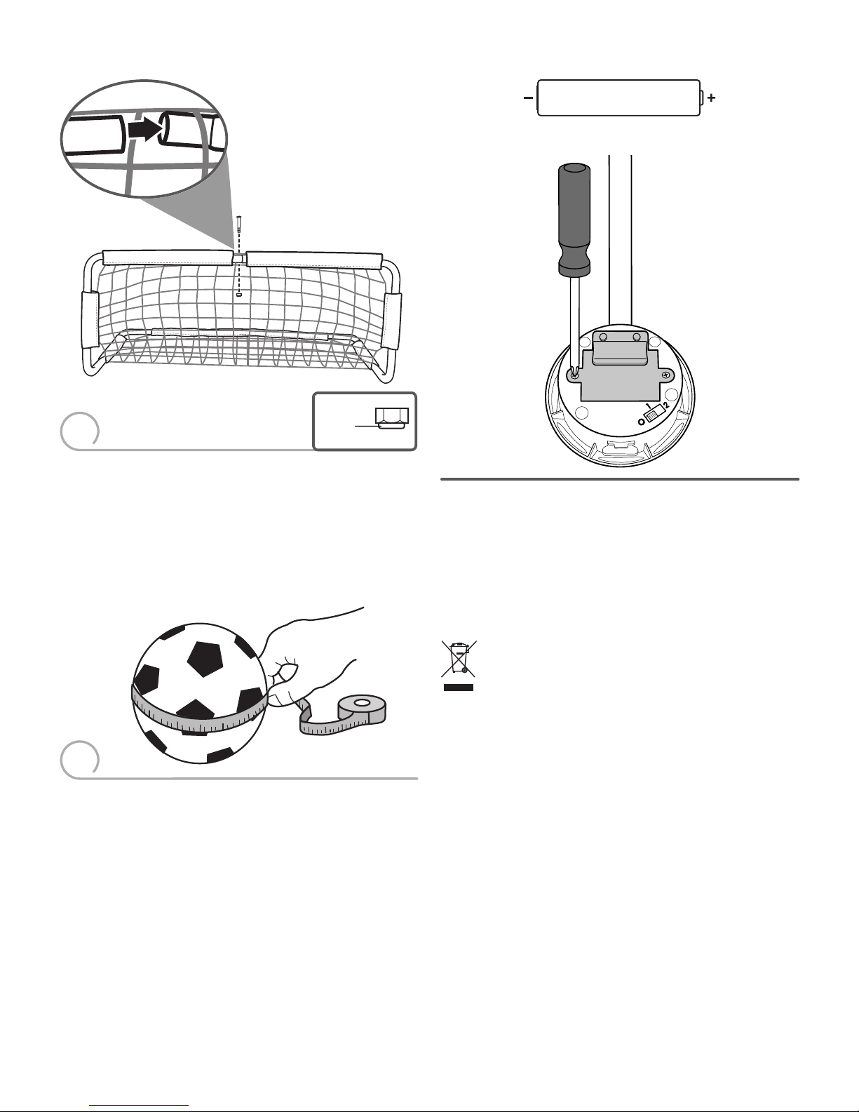
• Insert an inflation pin (not included) into a ball.
• Attach the pump (not included) to the pin.
• Inflate the ball to a circumference of 15½ (39 cm), until firm.
Do not over-inflate.
• After inflating the ball, remove the pin.
• Fit the ends of the tubes together.
• Fit a lock nut, rounded side out, into the hex hole on the inside of
the tube assembly.
• Insert a screw through the hole in the outside of the tube
assembly.
• While holding the lock nut in place with your thumb, tighten
the screw.
Rounded
Side
Battery Installation
BATTERY SAFETY INFORMATION
In exceptional circumstances, batteries may leak fl uids that can cause
a chemical burn injury or ruin your product. To avoid battery leakage:
• Do not mix old and new batteries or batteries of different types:
alkaline, standard (carbon-zinc) or rechargeable (nickel-cadmium).
• Insert batteries as indicated inside the battery compartment.
• Remove batteries during long periods of non-use. Always remove
exhausted batteries from the product. Dispose of batteries safely.
Do not dispose of the product in a fire. The batteries inside may
explode or leak.
• Never short-circuit the battery terminals.
• Use only batteries of the same or equivalent type, as recommended.
• Do not charge non-rechargeable batteries.
• Remove rechargeable batteries from the product before charging.
• If removable, rechargeable batteries are used, they are only to be
charged under adult supervision.
• Loosen the screws in the battery compartment door and remove
the battery compartment door.
• Insert three AAA (LR03) alkaline batteries into the
battery compartment.
• Replace the battery compartment door and tighten the screws.
• When sound becomes faint or stops, it’s time for an adult to
replace the batteries.
• If this toy begins to operate erratically, you may need to reset the
electronics. Slide the power/mode switch off and then back on.
1,5V x 3
AAA (LR03)
• Protect the environment by not disposing of this product
with household waste (2012/19/EU). Check your local
authority for recycling advice and facilities.
For longer life, use alkaline batteries.
Page 7
7
Beginner
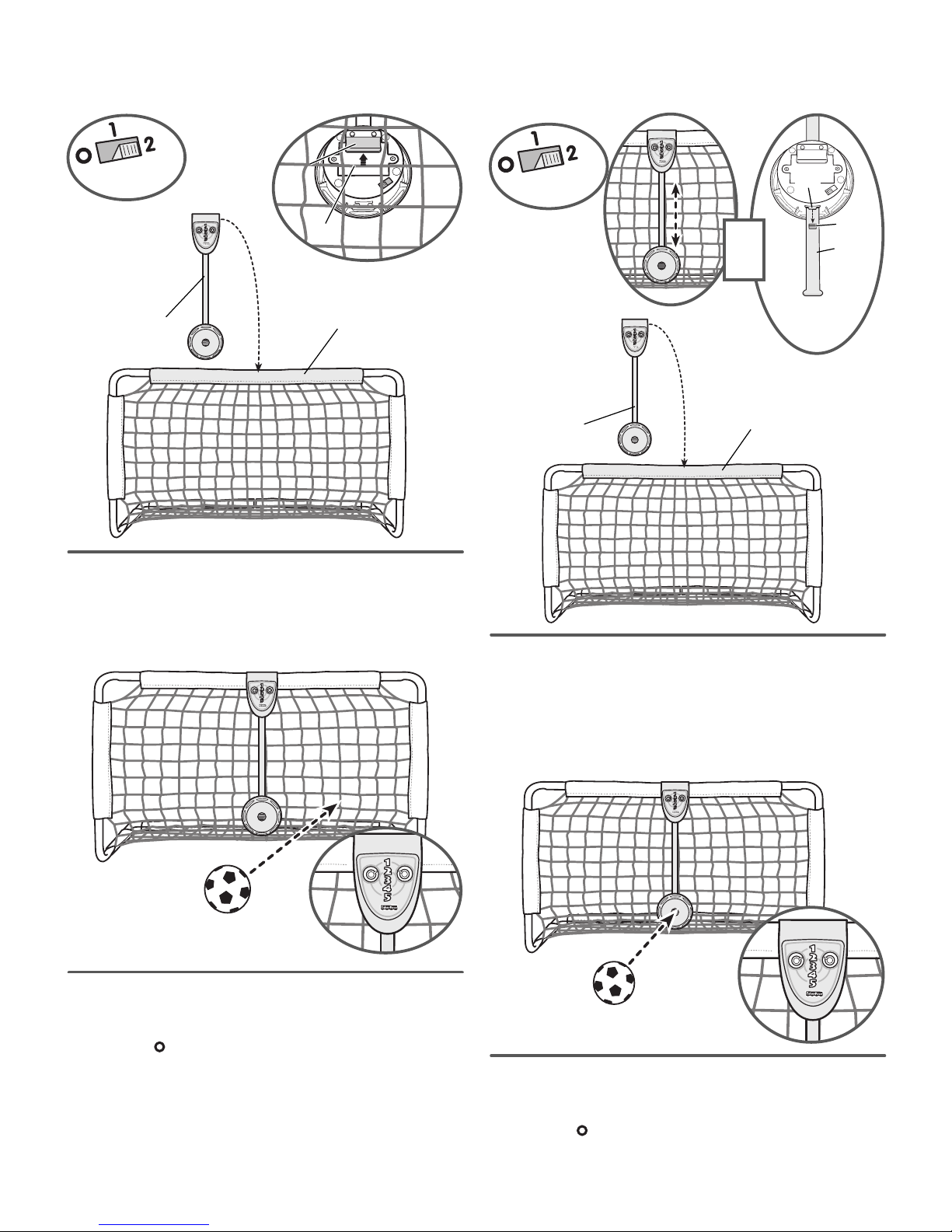
• Locate the power/mode switch on the back of the target. Slide the
switch to 1 for beginners.
• Fit the target onto the top edge of the frame.
• Fit the tab on the back of the target onto a net loop.
Beginners score fun sounds when the ball hits the net!
Top Edge
of the Frame
Target
Tab
Tab
Net
• Your little player hears fun sounds each time the ball hits the net.
• Turn the knob on the scorekeeper to record your goal!
• When you’re finished playing, slide the power/mode switch on the
target to the OFF position.
Scorekeeper
Scorekeeper
Pro
• Locate the power/mode switch on the back of the target. Slide the
switch to 2 for more advanced players.
• Fit the target onto the top edge of the frame.
Hint: You can raise or lower the target. Push the target up or down
into any of three positions and secure it by inserting the tab on the
back of the target into the pockets on the back of the target strap.
• Hit the target with the ball for fun sounds!
• Turn the knob on the scorekeeper to record your goal!
• When you’re finished playing, slide the power/mode switch on the
target to the OFF position.
Hit the target like a pro for fun sounds!
Power/Mode
Power/Mode
Switch
Switch
Target
Strap
Pocket
Tab
Back View
Back View
of Target
of Target
Move
Target
Up or
Down
Target
Top Edge of
the Frame
Scorekeeper
Scorekeeper
Power/Mode
Power/Mode
Switch
Switch
Page 8
Consumer Information
CARE
• The frame and net may be wiped clean using a mild cleaning
solution and a damp cloth. Do not use bleach. Do not use harsh
or abrasive cleaners. Rinse clean with water to remove residue.
Do not immerse this toy.
• To prolong the life of the net, store this toy indoors.
• Periodically check all fasteners regularly to be sure they are tight.
If the fasteners are not tight, tighten them as necessary.
FCC STATEMENT (UNITED STATES ONLY)
This equipment has been tested and found to comply with the limits
for a Class B digital device, pursuant to Part 15 of the FCC rules.
These limits are designed to provide reasonable protection against
harmful interference in a residential installation.This equipment
generates uses and can radiate radio frequency energy and, if
not installed and used in accordance with the instructions, may
cause harmful interference to radio communications.However,
there is no guarantee that interference will not occur in a particular
installation.If this equipment does cause harmful interference to
radio or television reception, which can be determined by turning
the equipment off and on, the user is encouraged to try to correct
the interference by one or more of the following measures:
• Reorient or relocate the receiving antenna.
• Increase the separation between the equipment and receiver.
• Consult the dealer or an experienced radio/TV technician for help.
NOTE: Changes or modifications not expressly approved by the
manufacturer responsible for compliance could void the user’s
authority to operate the equipment.
This device complies with Part 15 of the FCC Rules. Operation
is subject to the following two conditions: (1) This device may
not cause harmful interference, and (2) this device must accept
any interference received, including interference that may cause
undesired operation.
CONSU
MER
ASSISTANCE
1-800-432-5437 (US & Canada)
1300 135 312 (Australia)
Fisher-Price, Inc., 636 Girard Avenue, East Aurora, NY 14052.
Hearing-impaired consumers: 1-800-382-7470.
Outside the United States:
Canada: Mattel Canada Inc., 6155 Freemont Blvd.,
Mississauga, Ontario L5R 3W2; www.service.mattel.com.
Great Britain: Mattel UK Ltd, Vanwall Business Park,
Maidenhead SL6 4UB. Helpline: 01628 500303.
www.service.mattel.com/uk
Mattel Europa B.V., Gondel 1, 1186 MJ Amstelveen, Nederland.
Australia: Mattel Australia Pty. Ltd., 658 Church Street,
Locked Bag #870, Richmond, Victoria 3121 Australia.
New Zealand: 16-18 William Pickering Drive,
Albany 1331, Auckland.
CAN ICES-3 (B)/NMB-3 (B)
Operation is subject to the following two conditions: (1) this device
may not cause interference, and (2) this device must accept any
interference, including interference that may cause undesired
operation of the device.
L’utilisation de ce dispositif est autorisée seulement aux conditions
suivantes : (1) il ne doit pas produire de brouillage et (2) il doit
pouvoir tolérer tout brouillage radioélectrique reçu, même si ce
brouillage est susceptible de compromettre son fonctionnement.
©2016 Mattel. All Rights Reserved. DTM21-0970
PRINTED IN CHINA 1101148721-DOM
 Loading...