

Page 1

Owner’s
Manual
Model C4492 and H0127
Page 2

Page 3

2
TABLE OF CONTENTS
TABLE OF CONTENTS
Important Information . . . . . . . . . . . . . . . . . . . . . . . . . . . . . . . . . .3
Parts . . . . . . . . . . . . . . . . . . . . . . . . . . . . . . . . . . . . . . . . . . . . . . .8
Fasteners . . . . . . . . . . . . . . . . . . . . . . . . . . . . . . . . . . . . . . . . . . . .7
Battery Installation . . . . . . . . . . . . . . . . . . . . . . . . . . . . . . . . . . . .9
Assembly Tip . . . . . . . . . . . . . . . . . . . . . . . . . . . . . . . . . . . . . . . .10
Decoration . . . . . . . . . . . . . . . . . . . . . . . . . . . . . . . . . . . . . . . . . .11
Assembly . . . . . . . . . . . . . . . . . . . . . . . . . . . . . . . . . . . . . . . . . . .13
Game Setup
Basketball, Football, Baseball . . . . . . . . . . . . . . . . . . . . . . . . .100
Soccer, Hockey, Golf . . . . . . . . . . . . . . . . . . . . . . . . . . . . . . . .106
Care . . . . . . . . . . . . . . . . . . . . . . . . . . . . . . . . . . . . . . . . . . . . . .112
Game Play
Basketball . . . . . . . . . . . . . . . . . . . . . . . . . . . . . . . . . . . . . . . .113
Football . . . . . . . . . . . . . . . . . . . . . . . . . . . . . . . . . . . . . . . . . .115
Baseball . . . . . . . . . . . . . . . . . . . . . . . . . . . . . . . . . . . . . . . . .117
Soccer . . . . . . . . . . . . . . . . . . . . . . . . . . . . . . . . . . . . . . . . . . .119
Hockey . . . . . . . . . . . . . . . . . . . . . . . . . . . . . . . . . . . . . . . . . .121
Golf . . . . . . . . . . . . . . . . . . . . . . . . . . . . . . . . . . . . . . . . . . . . .123
Storage . . . . . . . . . . . . . . . . . . . . . . . . . . . . . . . . . . . . . . . . . . .125
Troubleshooting Guide . . . . . . . . . . . . . . . . . . . . . . . . . . . . . . . .134
Consumer Information . . . . . . . . . . . . . . . . . . . . . . . . . . . . . . . .137
Page 4

3
IMPORTANT INFORMATION
IMPORTANT INFORMATION
• Please keep this Owner’s Manual for future reference, as it contains
important information.
• Adult assembly is required. You may need the assistance of another adult to
complete assembly.
• Approximate assembly time is 21/2-5 hours. We recommend the use of a power
screwdriver to reduce assembly time.
• Be sure to assemble the GameStationTMin the room it is intended to be used.
Do not use the GameStationTMin a room with direct sunlight. Do not use the
GameStationTMoutdoors.
•Tool required for assembly: Phillips screwdriver (not included).
•You may find it helpful to use an adjustable wrench to hold the M5 lock nuts while
tightening the M5 bolts and a slotted screwdriver to fit the goal net binding into the clips.
• Requires four, “C” (LR14) alkaline batteries (not included) for operation. Each fresh set of
batteries should last approximately 15 hours (of continuous use).
• Please identify all parts before assembly and save all packaging material until assembly
is complete to ensure that no parts are discarded.
• If you experience a problem, or are missing a part, please call us at
1-800-432-KIDS (5437) rather than return this product to the store.
Or, visit us on-line at www.fisher-price.com.
• Use only the balls and puck that are supplied with this product. Do not use with
regulation size (actual) sport balls and pucks.
• During assembly, do not step on the plastic connectors attached to the wires.
• Make sure the power switch on the back of the game selector is in the ON position.
Page 5
4
WARNING
CHOKING HAZARD
– Toy contains a small ball (golf ball).
Not for children under 3 years.
CAUTION
This product contains small parts
in its unassembled state.
Adult assembly is required.
Page 6

5
PARTS
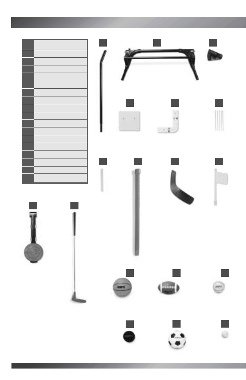
PARTS
1 2 L Tubes
(Left and Right)
2 2 Crossbars
3 2 Bases
(Left and Right)
4 2 Lower Net Clips
5 Putting Green
6 Goal
7 Wire Clip
8 2 Net Tubes (1A, 1B)
9 2 Net Tubes (2A, 2B)
10 2 Net Tubes (3A, 3B)
11 2 Feet
12 2 Nets
13 Chute
14
2 Chute Tubes (4A, 4B)
15 Ball Sensor
16 2 Plugs
17 Support Tubes
18 Game Selector
19 Retainer
20 2 Upper Net Clips
21 Backboard
22 Scoreboard
23 Backboard Tube
24 Rim
1
2
4
5
x 2
x 2
Left
Right
3
6
8
9
10
x 2
11
x 2
x 2
x 2
x 2
7
Page 7

6
x 2
12
13
14
15
16
18
17
19 20 21
22
23
24
x 2
x 2
x 2
x 2
Page 8
PARTS
PARTS
7
Parts not shown: Label sheets.
27
28 29 30
32
33 34
38
39
x 2
x 2
x 2
x 2
26
25
x 2
35
36
37
x 2
25 Handle Tubes
26 Handle
27 Handle Pivots
28 Connector Cover
29 2 Wire Covers
30 5 Wire Ties
31 2 Chute Tabs
32 Shaft
33 Blade
34 Flag
35 Target
36 Putter
37 2 Basketballs
38 2 Footballs
39 2 Baseballs
40 Puck
41 Soccer Ball
42 Golf Ball
Tip: Add the
flag in the
Game Setup
section.
Tip: Add the
target in the
Game Setup
section.
Tip: For Model H0127, there are three extra balls
(one basketball, one football, one baseball).
40
41
42
31
x 2
Page 9

8
FASTENERS
FASTENERS
M6 x 35 mm Bolt – 8
M5 x 75 mm Bolt – 2
#8 x 15 mm Screw – 25
M5 x 29 mm Bolt – 20
#8 x 37 mm Screw – 8
M5 Lock Nut – 16
M6 Lock Nut – 8
These lock nuts are not
located in a parts bag.
They are fitted inside
various plastic parts.
Tip: All fasteners shown actual size.
Note: Tighten and loosen all bolts and screws with a
Phillips screwdriver. Do not over-tighten the fasteners.
We’ve included extra fasteners for your convenience!
Page 10
9
BATTERY INSTALLATION
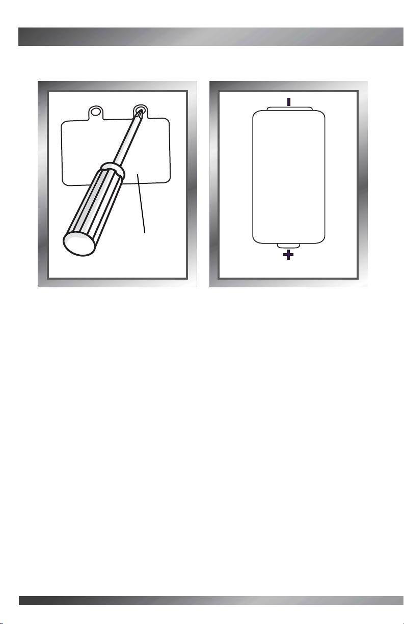
BATTERY INSTALLATION
• Loosen the screws in the battery compartment door on the back of the scoreboard.
Remove the battery compartment door.
• Insert four "C" (LR14) alkaline batteries.
• Replace the battery compartment door and tighten the screws.
Tip: When sounds or lights from the GameStationTMbecome faint or stop,
it’s time for an adult to change the batteries!
Battery
Compartment
Door
Tip: We recommend the use of alkaline batteries for longer battery life!
BATTERY SAFETY INFORMATION
Batteries may leak fluids that can cause a chemical burn injury or ruin your toy.
To avoid battery leakage:
• Do not mix old and new batteries or batteries of different types: alkaline, standard
(carbon-zinc) or rechargeable (nickel-cadmium).
•Insert batteries as indicated inside the battery compartment.
• Remove batteries during long periods of non-use.Always remove exhausted batteries
from the toy. Dispose of batteries safely. Do not dispose of batteries in a fire. The batteries
may explode or leak.
• Never short-circuit the battery terminals.
• Use only batteries of the same or equivalent type, as recommended.
• Do not charge non-rechargeable batteries.
• Remove rechargeable batteries from the toy before charging.
• If removable, rechargeable batteries are used, they are only to be charged
under adult supervision.
1.5V x 4
"C" (LR14)
SHOWN ACTUAL SIZE
Page 11
10
ASSEMBLY TIP
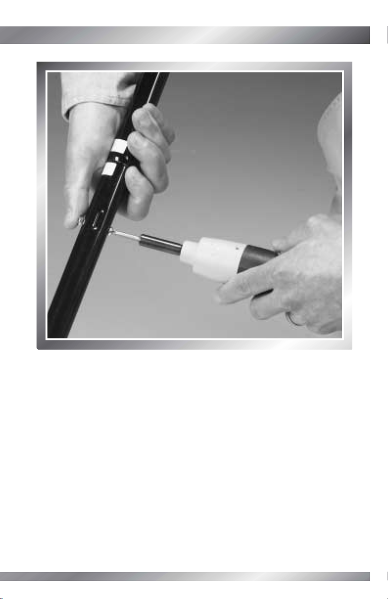
ASSEMBLY TIP
• When tightening bolts in tubes, you will need to press the lock nut into the opposite side
of the tube (the hex hole). Place your thumb on the lock nut while tightening bolt with a
Phillips screwdriver.
Tip: You may want to use an adjustable wrench to hold the lock nut in place.
Page 12

DECORATION
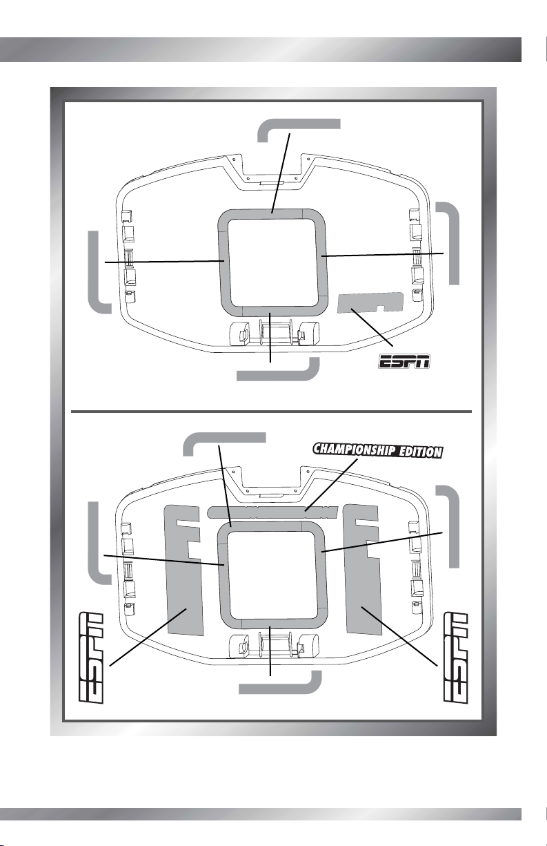
DECORATION
• Before applying the labels, wipe the surface of the scoreboard, backboard, game
selector, target and putting green with a clean, dry cloth to remove any dust or oils.
• Apply the labels as indicated in the illustrations.
Strikeouts
Down
Points
Overtime
Pitches
Attempts
50 40 30 20 10 TD
123balls 1 2strikes outs
1
4
3
6
5
7
8
2
11
Select Game
To Play
Select Sport
Press Start
1
2
3
START
BASKETBALL
BASEBALL
FOOTBALL
HOCKEY
SOCCER
GOLF
VOLUME
FREE PLAY
GAME PLAY
BEAT THE CLOCK
PERFECT GAME
3 (Model C4492)
1 (Model H0127)
9 (Model C4492)
8 (Model H0127)
8 (Model C4492)
7 (Model H0127)
1 (Model C4492 Only)
10 (Model C4492)
6(Model H0127)
Page 13
12
4
7
Model C4492
Model H0127
5
6
2
2
10
5
3
4
99
Page 14
13
ASSEMBLY
ASSEMBLY
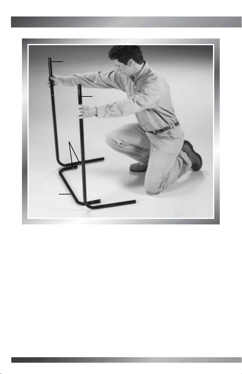
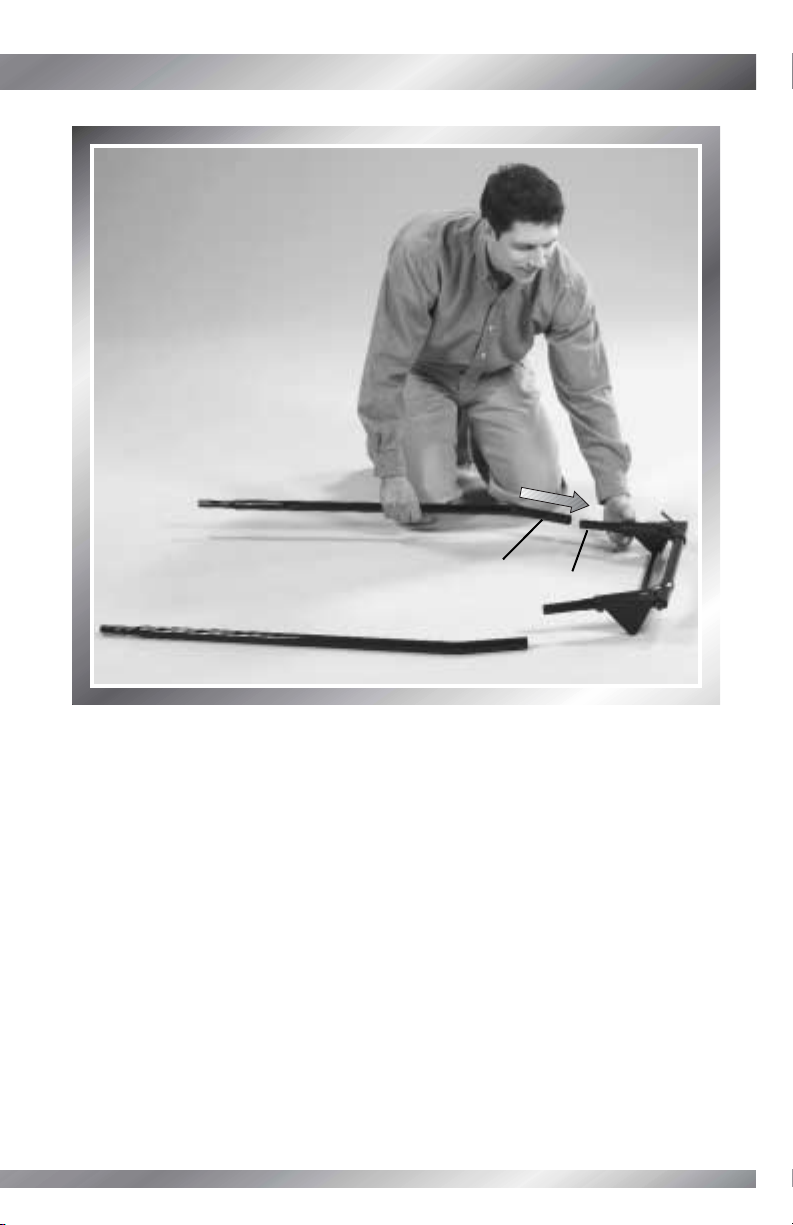
STEP 1
• Position the L tubes on either side of a crossbar, as shown.
Tip: The L tubes are slightly different! One of the L tubes has a white dot
on the lower portion.
•Match the white dot on the crossbar with the white dot on the L tube.
Crossbar
L Tube
L Tube
White
Dots
Page 15
14
M5 Lock Nuts
M5 x 29 mm
Bolts
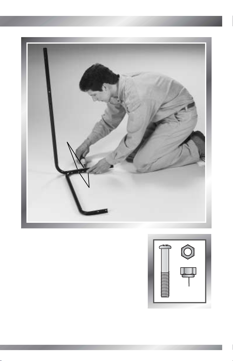
STEP 2
Tip: You will need to lean the assembly against
a wall or an object to complete this step.
• Insert an M5 x 29 mm bolt through the outside of the
L tube.
• Fit an M5 lock nut, rounded side out, to the matching
hex hole in the crossbar.
• While holding the lock nut in place, tighten the bolt.
• Fit another M5 lock nut and M5 x 29 mm bolt to the
crossbar and L tube and tighten.
Tip: If you cannot attach the M5 lock nut to the end
of the M5 x 29 mm bolt, you have assembled the crossbar incorrectly to the
L tubes. Turn the crossbar around. Make sure the white dot on the crossbar
matches the white dot on one of the L tubes.
Rounded
Side
Page 16
15
ASSEMBLY
ASSEMBLY
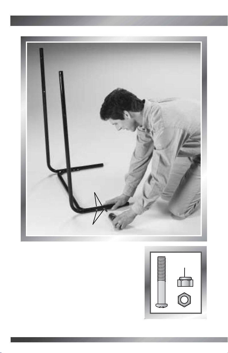
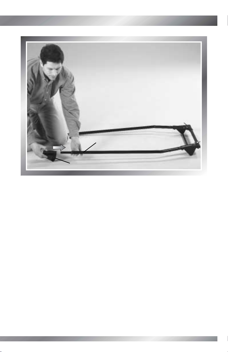
STEP 3
Tip: You will need to lean the assembly against
a wall or an object to complete this step.
• Insert an M5 x 29 mm bolt through the outside
of the other L tube.
• Fit an M5 lock nut, rounded side out, to the
matching hex hole in the crossbar.
• While holding the lock nut in place, tighten the bolt.
• Fit another M5 lock nut and an M5 x 29 mm bolt
to the crossbar and L tube and tighten.
M5 Lock Nuts
M5 x 29 mm Bolts
Rounded
Side
Page 17
16
STEP 4
• Fit the lower net clip into the slot in one of the bases.
Base Slot
Lower Net Clip
Page 18

17
ASSEMBLY
ASSEMBLY
STEP 5
• Insert three #8 x 15 mm screws into the lower net clip
and tighten.
• Repeat assembly steps 4 and 5 to assemble the other
lower net clip to the other base.
Lower Net Clip
#8 x 15 mm
Screws
Page 19
18
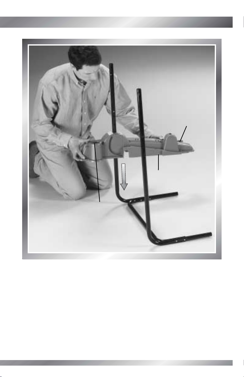
STEP 6
• With the lower net clip facing out, slide the left base onto the tube assembly, as shown.
Tip: The left base includes a hockey stick storage area.
Lower Net
Clip
Left Base
Hockey Stick
Storage
Page 20

19
ASSEMBLY
ASSEMBLY
STEP 7
• With the lower net clip facing out, slide the right base onto the tube assembly, as shown.
Right Base
Lower Net Clip
Page 21

20
STEP 8
•Turn the assembly so that the bottom
faces you.
• Insert four #8 x 37 mm screws into the
L tubes and tighten.
• Return the assembly to the upright position.
BACK VIEWBOTTOM VIEW
#8 x 37 mm
Screws
Page 22

21
ASSEMBLY
ASSEMBLY
STEP 9
• With the wire toward the lower net clips, fit the putting green to the base assembly.
IMPORTANT! Make sure the wire is toward the lower net clips.
Putting Green
Wire
Lower Net
Clip
Lower Net Clip
Page 23

22
STEP 10
• Insert six #8 x15 mm screws into the putting green
and tighten.
#8 x 15 mm
Screws
Page 24
23
ASSEMBLY
ASSEMBLY
Bar
STEP 11
• Position the goal so that the bar faces you and the wire is on the right.
Wire
CORRECT
INCORRECT
Page 25

24
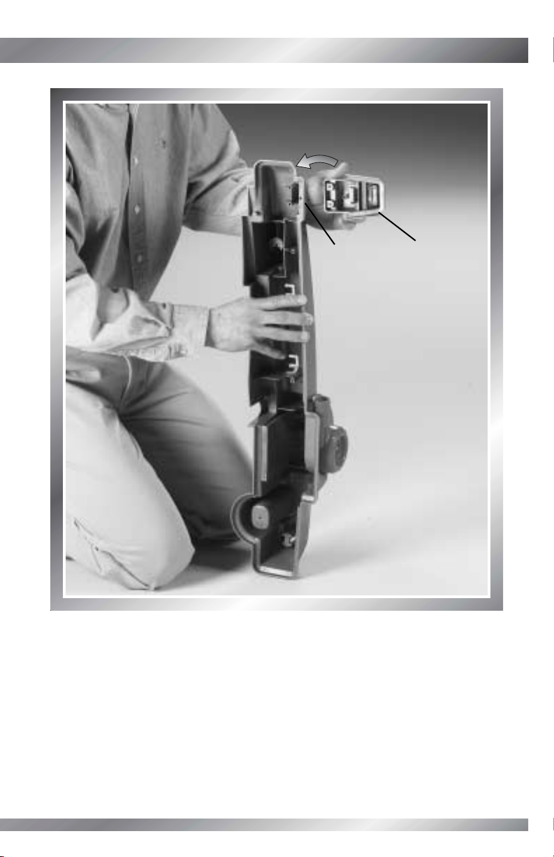
STEP 12
• Place the goal, with the bar facing up, onto the base assembly.
• First, read and then remove the label from the hole in the base. Throw the label away.
• Fit the goal wire down through the hole in the base.
Goal Wire
Hole
Label
Bar Up
Page 26
25
ASSEMBLY
ASSEMBLY
STEP 13
• Lift the assembly to pull the wire completely through the hole.
BACK VIEWBOTTOM VIEW
Page 27

26
STEP 14
• Lower the assembly so that it is upright.
• Make sure the bar on the goal faces forward,
and the goal wire is pressed into the channel
at the end of the tube.
• Fit the ends of the goal into the holes in the
base assembly. Push to snap into place.
Goal Tubes
Base Holes
Bar
Goal Wire
in Channel
BACK VIEWFRONT VIEW
Page 28
27
ASSEMBLY
ASSEMBLY
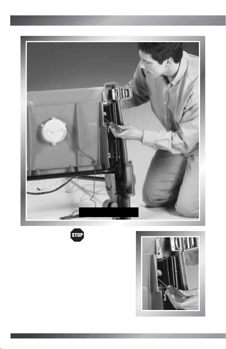
STEP 15
If you forgot to insert the goal wire down
through the hole in the base, you can remove
the goal!
•Tip the assembly backward.
• Press the tab on a goal tube with a slotted
screwdriver.
• Pull the goal tube to unlatch it.
• Repeat this procedure to unlatch the other goal
tube and remove the goal. Repeat Assembly
steps 12-14.
BACK VIEWBOTTOM VIEW
Page 29

28
BACK VIEW
Yellow Markings
on Binding
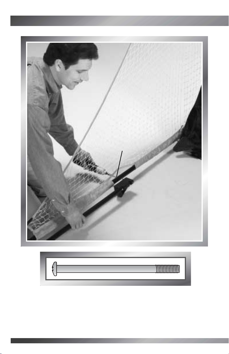
STEP 16
• Find the yellow markings on the back of the goal
net binding. You will insert the binding between the
yellow markings into the center clip on the back edge
of the putting green.
Putting Green
Center Clip
Goal Net
Binding
Page 30

29
ASSEMBLY
ASSEMBLY
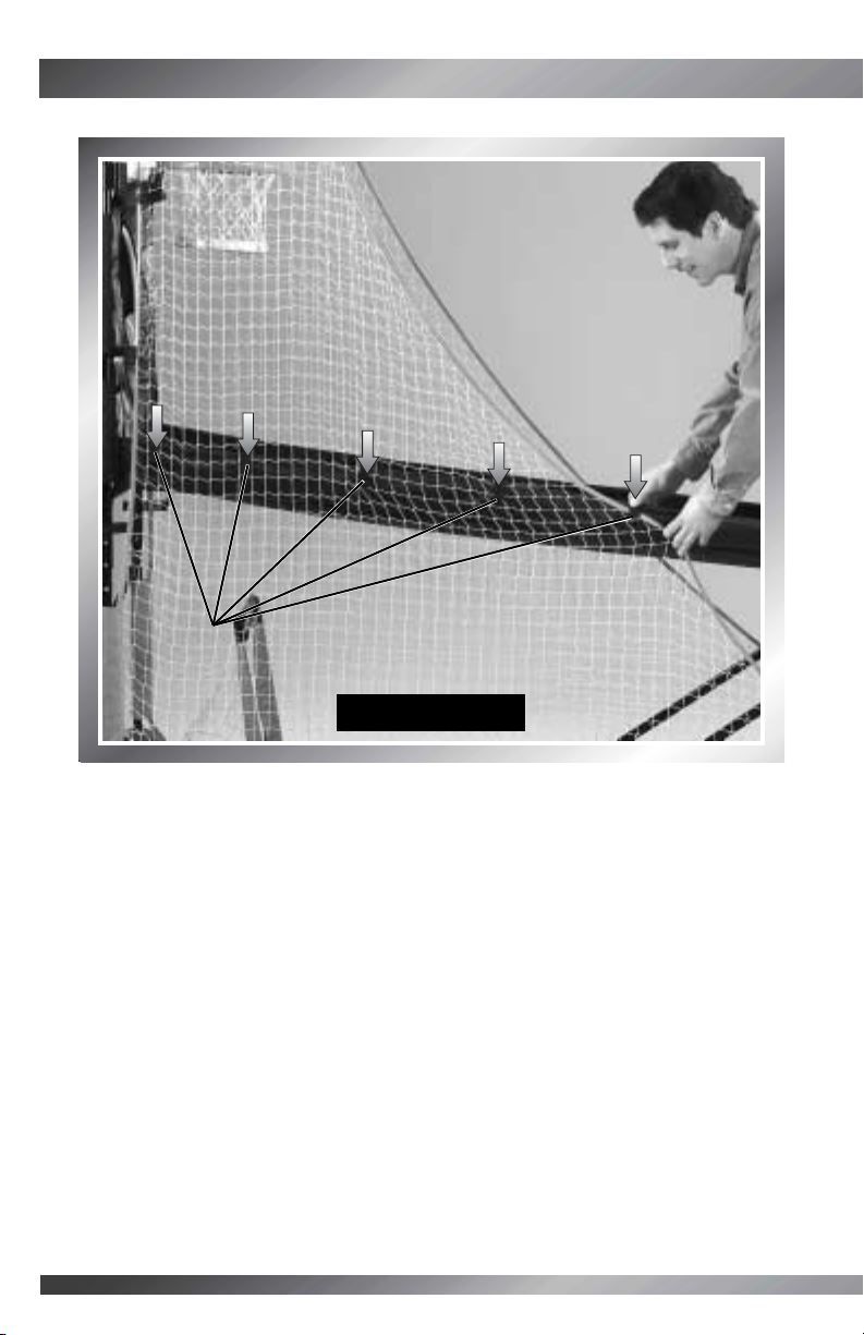
STEP 17
• Now, fit the binding into the remaining eight clips in the putting green and bases.
Tip: You may need to use a flat end screwdriver to fit the binding into
each clip.
Clips
Clips
Clips
Clips
BACK VIEW
Page 31

30
STEP 18
•Tip the assembly so the bottom faces you and the hockey stick and putter storage
areas on the base are upright.
• Fit the golf cup wire through the hole in the base.
Golf Cup Wire
Base Hole
BACK VIEWBOTTOM VIEW
Hockey Stick
Storage Area
Page 32

31
ASSEMBLY
ASSEMBLY
STEP 19
• Fit the goal wire through the same hole in the base.
Goal Wire
Hole in Base
BACK VIEWBOTTOM VIEW
Page 33

32
STEP 20
• Remove the backing from the wire clip. Throw the backing away.
• Press to attach the wire clip inside the base, as shown.
Wire Clip
BACK VIEWBOTTOM VIEW
Page 34

33
ASSEMBLY
ASSEMBLY
STEP 21
• Fit the goal and golf cup wires into the wire clip.
Clip
Goal and Golf
Cup Wires
BACK VIEWBOTTOM VIEW
Page 35

34
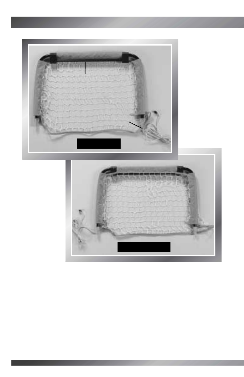
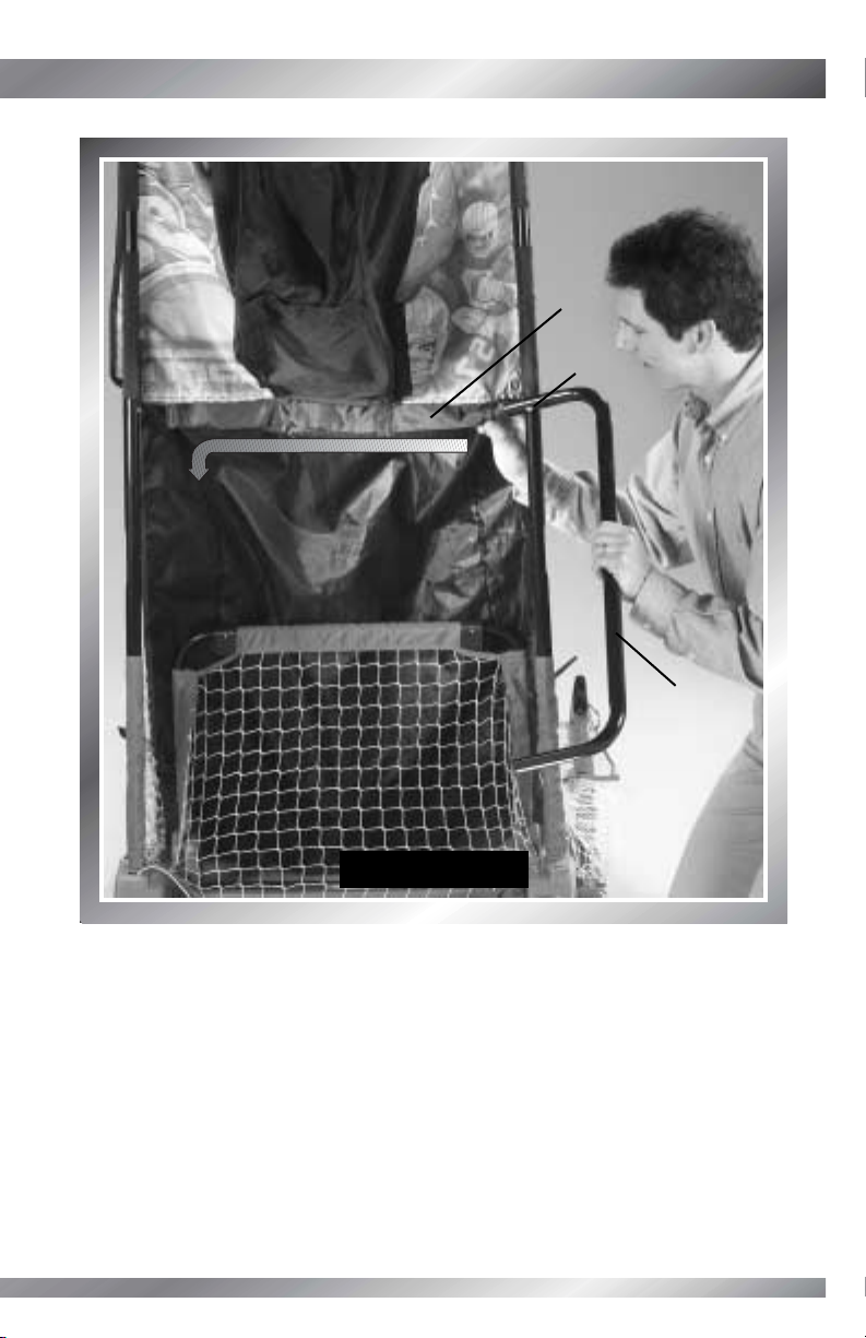
STEP 22
• Locate the net tubes labeled 1, 2 and 3. Net Tube 3 is the shortest (251/4"), followed
by Net Tube 2 (261/2") and then the longest, which is Net Tube 1 (271/2").
• The net tubes are also labeled A and B. Assemble Net Tubes 1A, 2A and 3A.
Then, assemble Net Tubes 1B, 2B and 3B.
Net Tube 3
Net Tube 2
Net Tube 1
251/4"
261/2"
271/2"
Page 36

STEP 23
• Insert net tube 2A into net tube 1A.
• Fit an M5 lock nut, rounded side out, to the hex
hole in net tube 1A.
• Insert an M5 x 29 mm bolt through the opposite
side of net tube 1A. While holding the lock nut
in place, tighten the bolt.
35
ASSEMBLY
ASSEMBLY
Net Tube 2A
M5 Lock Nut
Net Tube 1A
M5 x 29 mm Bolt
Rounded
Side
Page 37

36
Net Tube 3A
Net Tube 2A
M5 x 29 mm Bolt
M5 Lock Nut
STEP 24
• Insert net tube 3A into net tube 2A.
• Fit an M5 lock nut, rounded side out, to the hex
hole in net tube 2A.
• Insert an M5 x 29mm bolt through the opposite
side of net tube 2A. While holding the lock nut in
place, tighten the bolt.
• Repeat steps 23 and 24 to assemble the remaining
net tubes 1B, 2B and 3B.
Rounded
Side
Page 38

37
ASSEMBLY
ASSEMBLY
STEP 25
• Slide a foot onto the end of a net tube assembly.
Tip: The foot fits only to the wide end of a net tube assembly.
Foot
Net Tube Assembly
Page 39

38
M6 x 35 mm Bolt
STEP 26
• Insert an M6 x 35 mm bolt through the net tube assembly
and into the foot. Tighten the bolt.
Tip: Each foot includes an M6 lock nut.
• Repeat assembly steps 25 and 26 to assemble the other
foot to the other net tube assembly.
Tip: Set the net tube assemblies aside for
Assembly Step 29.
Page 40

39
ASSEMBLY
ASSEMBLY
STEP 27
• Position a net next to the base assembly so that the sleeves are toward the assembly
and the strap at the tip is furthest from the base assembly.
• Note the location of the back sleeve. You will fit this back sleeve onto the upright tube
in the next step.
Net
Base
Assembly
Back
Sleeve
Strap
BACK VIEWFRONT VIEW
Sleeves
Page 41

40
STEP 28
• Fit the net back sleeve onto the upright tube, as shown.
• Repeat Assembly steps 27 and 28 to fit the other net to the other upright tube.
Back Sleeve
Upright Tube
BACK VIEWFRONT VIEW
Page 42

41
ASSEMBLY
ASSEMBLY
STEP 29
• Fit the net tube assembly labeled 1A, 2A, 3A into the net sleeve closest to you, as shown.
Net Tube Assembly
Net Sleeve
BACK VIEWFRONT VIEW
Page 43

42
Step 30
• Continue to slide the net tube assembly labeled 1A, 2A, 3A through all three net
sleeves, as shown.
3 Net Sleeves
BACK VIEWFRONT VIEW
Page 44

43
ASSEMBLY
ASSEMBLY
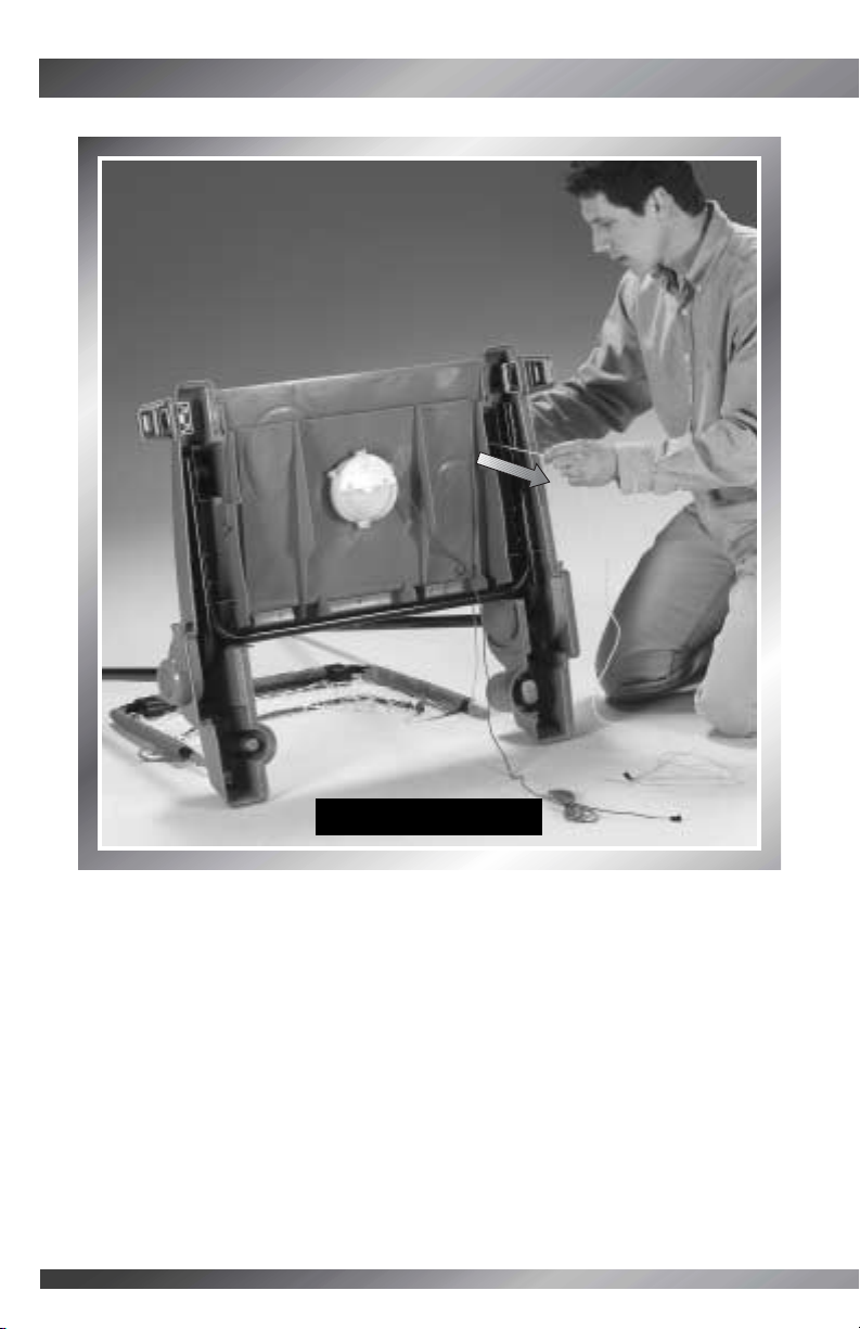
STEP 31
• Thread the strap through the slot in the top of the foot.
• Fold the strap onto itself to fasten.
• Repeat Assembly Steps 29-31 to assemble the other net tube assembly labeled
1B, 2B, 3B to the other net.
Foot Slot
Strap
Page 45

44
BACK VIEWSIDE VIEW
Net Pivot
Net Tube
STEP 32
• Fit a net tube into a net pivot on one side of the base.
• Fit the other net tube into the net pivot on the other side of the base.
Tip: The net tubes are designed to go into the net pivots one way. If the net tube
does not fit into the net pivot, remove the net tube from the net sleeves. Replace
it into the other net sleeves, and repeat this step.
Page 46
45
ASSEMBLY
ASSEMBLY
STEP 33
• Insert an M5 x 29 mm bolt into a net pivot and tighten.
Tip: Each net pivot includes an M5 lock.
• Fasten the other net tube to the other net pivot using an
M5 x 29 mm bolt.
• Pull on the net tubes. If you can remove them from the net pivots, you
have assembled them incorrectly. Remove the M5 x 29 mm bolts
and the net tubes. Fit the net tubes into the other net and net pivot.
Repeat Assembly Steps 29-32.
M5 x 29 mm Bolt
BACK VIEWSIDE VIEW
Net Pivot
Page 47
46
STEP 34
• Position the chute between the upright tubes. The ball opening should face the side nets.
• Now, fit both chute sleeves onto an upright tube.
2 Chute
Sleeves
Upright
Tube
BACK VIEWFRONT VIEW
Upright
Tube
Ball Opening
Page 48
47
ASSEMBLY
ASSEMBLY
STEP 35
• Fit the sleeves on the other side of the chute onto the other upright tube.
2 Chute
Sleeves
Upright Tube
BACK VIEWFRONT VIEW
Page 49

Chute
Tube 4A
Chute
Tube 4B
Upright
Tube
Upright
Tube
BACK VIEWFRONT VIEW
STEP 36
• Fit the chute tubes 4A and 4B into the upright tubes. You may need to twist the chute
tubes into place.
Tip: If the chute tubes 4A and 4B do not fit into the upright tubes after twisting
them, try placing them on the opposite upright tube.
48
Page 50

49
ASSEMBLY
ASSEMBLY
M5 Lock Nut
M5 x 29 mm
Bolt
STEP 37
• Fit an M5 lock nut, rounded side out, to the
hex hole on the chute tube 4A.
• Insert an M5 x 29 mm bolt through the opposite
side of the chute tube 4A. While holding the lock
nut in place, tighten the bolt.
• Repeat this procedure to fasten the other
chute tube 4B.
BACK VIEWFRONT VIEW
Rounded
Side
Page 51
50
STEP 38
• Fit the end of the crossbar (with the white dot) into the sleeve on the back of
the chute.
• Slide the crossbar completely through the sleeve.
Sleeve
Crossbar
BACK VIEW
White Dot
Page 52

51
ASSEMBLY
ASSEMBLY
Fasteners
STEP 39
• Open the fasteners on one side of the chute, as shown.
SIDE VIEW
Page 53

52
STEP 40
• Position the ball sensor with the tube down and the wire toward the chute.
• Fit the ball sensor, wire end first, into the large opening in the chute.
Ball Sensor
Tube
Wire
SIDE VIEW
Large
Opening
Page 54

ASSEMBLY
ASSEMBLY
STEP 41
• Continue to feed the ball sensor tube and wire out through the smaller opening in
the chute.
• Fit one end of the ball sensor tube into the slot in a chute tube.
Ball Sensor
Tube
Chute
Tube
Slot
BACK VIEW
53
Page 55
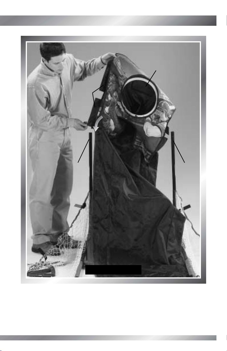
STEP 42
• Fit the other end of the ball sensor tube into the slot in the other chute tube.
Tip: You may need to pull the chute tubes apart slightly to fit the ball
sensor tube into the chute tubes’ slots.
Ball Sensor
Tube
54
BACK VIEW
Chute
Tube
Slot
Page 56

55
ASSEMBLY
ASSEMBLY
Slots
Flat Tabs
STEP 43
• Pull the fabric on the chute ring up
to expose the flat tabs.
• Insert and “snap” the flat tabs on
the chute ring into the slots in the
ball sensor.
BACK VIEWFRONT VIEW
Chute Ring
Page 57

56
STEP 44
• Press to insert the hooked tabs on the chute ring into the slots in the ball sensor.
Slots
Hooked
Tabs
Page 58

57
ASSEMBLY
ASSEMBLY
Chute Straps
Ball Sensor
STEP 45
• Fasten all three chute straps around
the ball sensor.
Tip: You may need to lift or lower the
ball sensor to fasten the straps around it.
Page 59

STEP 46
• Fit the ends of the crossbar to the upright tubes.
Tip: Make sure the white dot on one end of the
crossbar and one of the upright tubes match.
If they do not match, remove the crossbar and
replace so that the white dots match.
• Fit two M5 lock nuts, rounded side out, to
the hex holes in the crossbar (one at a time).
• Insert two M5 x 29 mm bolts through the upright tubes. While holding the lock nuts in
place (one at a time) tighten the bolts.
• Repeat this procedure to fasten the other side of the crossbar to the upright tubes.
58
Crossbar
M5 x 29 mm
Bolt
M5 Lock Nuts
BACK VIEW
BACK VIEW
Rounded
Side
Page 60

59
ASSEMBLY
ASSEMBLY
BACK VIEW
BACK VIEW
Small Hole
Plug
Crimped
End
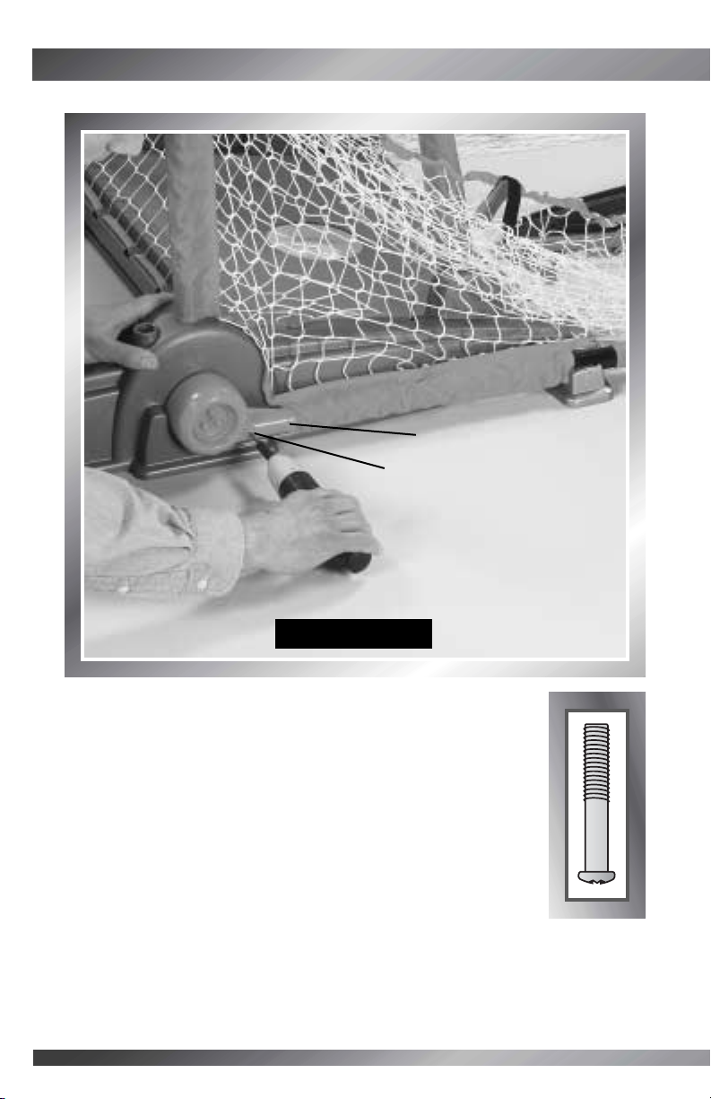
STEP 47
• Fit a plug into the crimped end of a support tube.
• Fit a support tube into the small hole in a base. Push the support tube down to snap
into place. Make sure the support tube is fitted to the inside of the upright tube.
• Fit an M6 x 35 mm bolt through the outside of the upright tube and tighten.
Tip: Each plug (inside the support tube) includes an M6 lock nut.
• Repeat this procedure to assemble the other plug and support tube to the assembly.
M6 x 35 mm
Bolt
Support Tube
Page 61

60
STEP 48
• Fit the game selector to a chute tube.
Tip: The game selector fits to only one chute tube.
Game
Selector
Chute
Tube
BACK VIEWFRONT VIEW
Page 62

61
ASSEMBLY
ASSEMBLY
STEP 49
• Fit the game selector retainer to the game selector and chute tube.
Game Selector
Retainer
BACK VIEWFRONT VIEW
Page 63
62
#8 x 15 mm
Screws
BACK VIEW
BACK VIEW
STEP 50
• Insert three #8 x 15 mm screws into the game selector
retainer and tighten.
Page 64

63
ASSEMBLY
ASSEMBLY
STEP 51
• Fit an upper net clip to the chute tube. Align the holes in the upper net clip and
chute tube.
Upper Net Clip
Chute Tube
BACK VIEWFRONT VIEW
Page 65

M6 x 35 mm Bolts
STEP 52
• Insert two M6 x 35 mm bolts through
the chute tube and into the upper net clip.
Tighten the bolts.
Tip: Each upper net clip includes two
M6 lock nuts.
• Repeat Assembly Steps 51 and 52 to assemble the other
upper net clip to the other chute tube.
BACK VIEWFRONT VIEW
64
Page 66

65
ASSEMBLY
ASSEMBLY
STEP 53
• Fit the wires on the scoreboard down through the slot in the top of the backboard.
Scoreboard Wires
Backboard Slot
Page 67

66
STEP 54
• Push to fit the scoreboard into place on the backboard.
Page 68

67
ASSEMBLY
ASSEMBLY
#8 x 15 mm Screws
STEP 55
• Insert four #8 x 15 mm screws into the
backboard and tighten.
Page 69

68
STEP 56
• Fit the backboard tube into the grooves on the backboard.
Backboard Tube
Grooves
Page 70

69
ASSEMBLY
ASSEMBLY
STEP 57
• While holding the backboard tube in place, slide the backboard onto the chute tubes.
Chute Tubes
Backboard Tube
BACK VIEW
BACK VIEW
Page 71

70
STEP 58
• Insert four #8 x 37 mm screws through
the chute tubes, backboard tube (only the
lower screws) and into the backboard.
Tighten the screws.
#8 x 37 mm
Screws
BACK VIEW
BACK VIEW
Page 72

71
ASSEMBLY
ASSEMBLY
Chute
Strap
Upper Net
Clip Slot
A
BACK VIEW
BACK VIEW
Buckle
B
C
A
B
C
STEP 59
• First, remove the fabric from the chute strap.
Throw the fabric away. Fit a chute strap through
the slot in the upper net clip .
• Next, fit the chute strap through the buckle on
the chute .
• Then, fold the chute strap over to attach .
• Repeat this procedure to fasten the other chute
strap to the other upper net clip.
Page 73

72
STEP 60
• First, read and then remove the label from the slot on the front of the backboard.
Tip: Be sure you insert the rim wire through this slot in the backboard.
BACK VIEWFRONT VIEW
Page 74

73
ASSEMBLY
ASSEMBLY
STEP 61
• Fit the rim wire through the slot in the backboard.
Rim Wire
Backboard Slot
BACK VIEW
FRONT VIEW
Page 75

74
STEP 62
• Push to “snap” the pegs on the rim into the hinge on the backboard.
Rim
Hinge
BACK VIEW
FRONT VIEW
Page 76
75
ASSEMBLY
ASSEMBLY
Peg
Hole
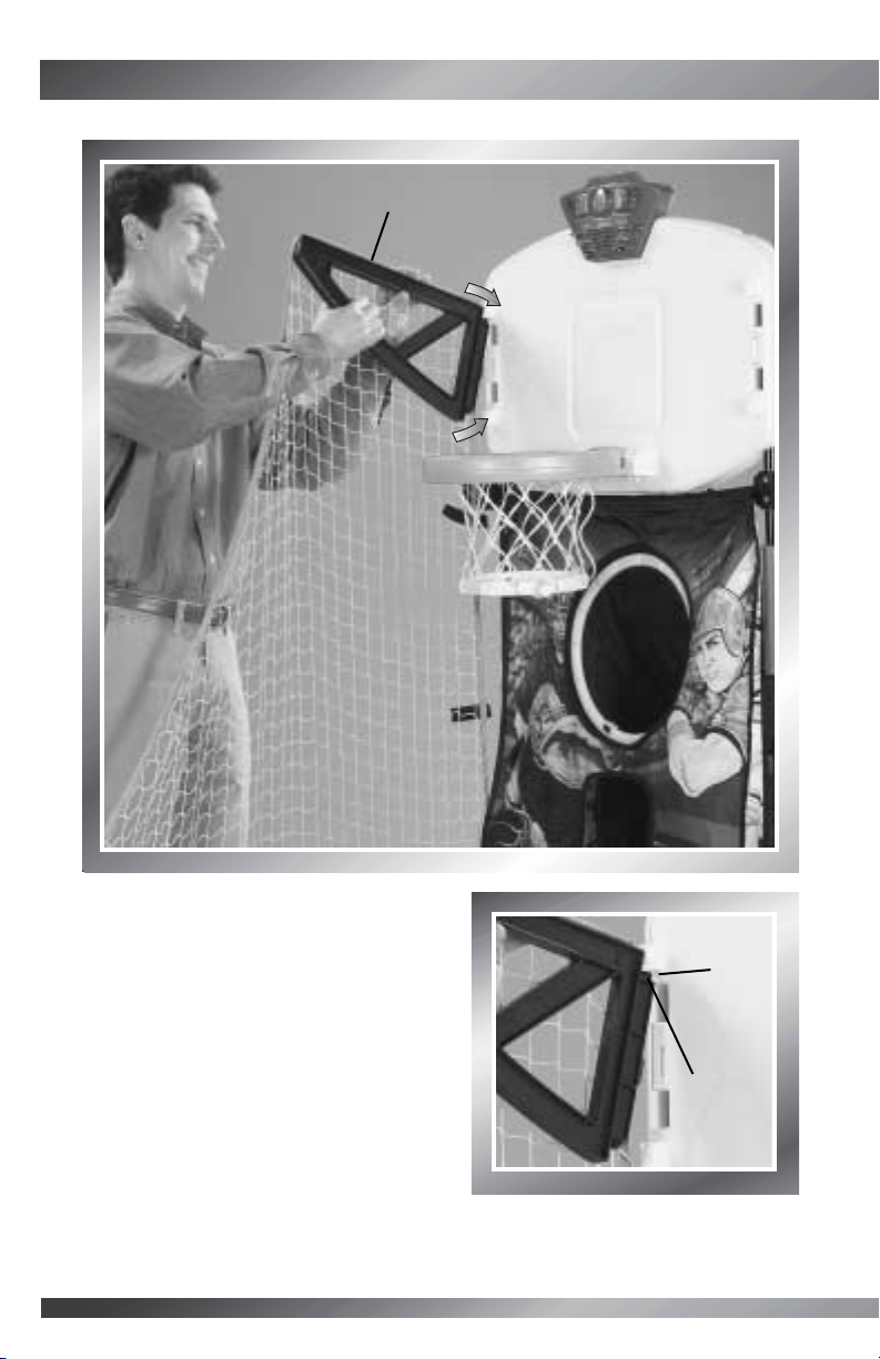
STEP 63
• Position the bracket on the net so that
the flat edge is up and the net is on the
outside of the bracket, as shown.
• At an angle, fit the upper peg on the net
bracket into the upper hole in the backboard.
• Then, slide the lower peg on the net bracket
into the lower hole in the backboard.
• Repeat this procedure to assemble the other
net bracket to the backboard.
Bracket Flat Edge Up
Page 77
76
STEP 64
• Place the handle and handle tubes on a flat surface.
• Fit a handle tube onto one end of the handle.
Handle Tube
Handle
Page 78

77
ASSEMBLY
ASSEMBLY
M5 x 29 mm
Bolt
M5 Lock Nut
STEP 65
• Fit an M5 lock nut, rounded side out, to the hex
hole in the handle tube.
• Insert an M5 x 29 mm bolt through the handle tube.
While holding the lock nut in place, tighten the bolt.
• Repeat Assembly Steps 64 and 65 to assemble
the other handle tube to the handle.
Rounded
Side
Page 79
78
STEP 66
• Position a handle pivot so that the long, flat edge faces up.
• Fit a handle pivot to one of the handle tubes.
Tip: If the handle pivot does not fit properly to the handle tube, try fitting the
other handle pivot to that handle tube.
Handle Tube
Handle Pivot
Page 80

79
ASSEMBLY
ASSEMBLY
STEP 67
• Insert an M5 x 29 mm bolt into the handle pivot and tighten.
Tip: The handle pivot includes an M5 lock.
• Repeat Assembly Steps 66 and 67 to assemble the other handle pivot
to the other handle tube.
M5 x 29 mm Bolt
Page 81

80
Handle
Pivots
Handle
Assembly
White
Dots
Fastener
Straps
White
Dots
STEP 68
• With the fastener straps up,
fit the handle assembly between
the net tubes.
IMPORTANT! Match the white dot
on the handle pivot with the white
dot on the net tube.
Page 82
ASSEMBLY
ASSEMBLY
M5 x 75 mm Bolt
Step 69
• Insert an M5 x 75 mm bolt through each net tube and into each handle pivot.
Tip: Each handle pivot includes an M5 lock nut.
•Tighten the bolt.
81
Page 83

82
Chute Clips
Lower Bar
Step 70
• Lift the handle.
• Attach the chute clips to the
lower bar on the handle.
Tip: Gently pull the clips from
the handle. If they remove easily,
you have probably assembled
them to the upper bar on the
handle. Remove the clips and
attach them to the lower bar
on the handle.
Clip on
Lower Bar
Page 84

ASSEMBLY
ASSEMBLY
STEP 71
• Remove the fabric on the strap. Throw the fabric away.
• Fasten the straps on the handle to the sides of the chute.
Handle Strap
83
Page 85

84
STEP 72
• Note the five wires from the various parts of the Game StationTMand the corresponding
five wires from the scoreboard.
Scoreboard
Wires
Wires from
Various Parts
of Game Station
TM
BACK VIEWBACK VIEW
Page 86

85
ASSEMBLY
ASSEMBLY
STEP 73
• Connect the blue wires, yellow wires, black wires, white wires and red wires.
Tip: If the wire connectors do not fit together, try turning one of the wires
over. Do not force the connectors together.
Page 87

86
STEP 74
• Fit the connectors inside the storage area on the back of the backboard.
IMPORTANT! Make sure all wires are connected.
Storage Area
Connectors
BACK VIEWBACK VIEW
Page 88

87
ASSEMBLY
ASSEMBLY
Storage Cover
#8 x 15 mm Screws
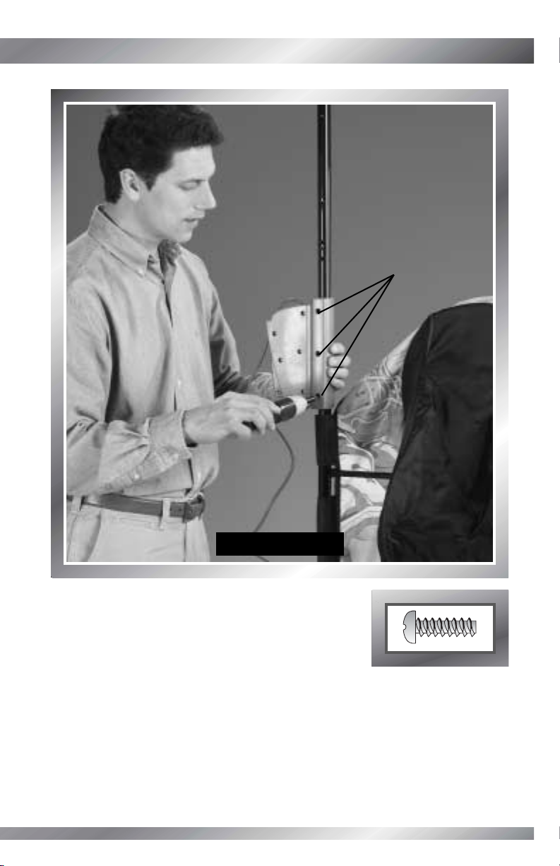
STEP 75
• Fit the storage cover onto the storage area.
• Insert two #8 x 15 mm screws and tighten.
BACK VIEWBACK VIEW
Page 89

88
STEP 76
• Fit all five wires under the tabs inside a wire cover.
BACK VIEWBACK VIEW
Tabs
Wire Cover
Page 90

89
ASSEMBLY
ASSEMBLY
STEP 77
•Turn the wire cover over. Fit the wire cover to the backboard, as shown.
• Fit the wires under the tabs inside the other wire cover.
Wire Cover
BACK VIEWBACK VIEW
Wire Cover
Tabs
Tabs
Page 91

90
#8 x 15 mm
Screws
STEP 78
• Fit four #8 x 15 mm screws into the wire covers
and tighten.
BACK VIEWBACK VIEW
Wire
Covers
Page 92
91
ASSEMBLY
ASSEMBLY
STEP 79
• Remove the fabric from the straps on each side of the chute (there are five on
each side). Throw the fabric away.
• Wrap the straps on each side of the chute around an adjacent loop in the net
and fasten.
Straps
SIDE VIEW
Page 93

92
STEP 80
• Remove the fabric from the straps. Throw the fabric away.
• Wrap the straps on the top, left side of the chute around the wires and the tube.
Fasten the straps.
Straps
BACK VIEW
Page 94

93
ASSEMBLY
ASSEMBLY
STEP 81
• Remove the fabric from the straps. Throw the fabric away.
• Wrap the straps on the middle, left side of the chute around the wires and the tube.
Fasten the straps.
Straps
BACK VIEW
Page 95

94
STEP 82
• Remove the fabric from the straps. Throw the fabric away.
• Wrap the straps on the bottom, left side of the chute around the wires and the tube.
Fasten the straps.
Straps
BACK VIEW
Page 96

ASSEMBLY
ASSEMBLY
STEP 83
• Remove the fabric from the straps. Throw the fabric away.
• Wrap the top, middle and bottom straps on the right side of the chute around the tube.
Fasten the straps.
Straps
95
BACK VIEW
Page 97
96
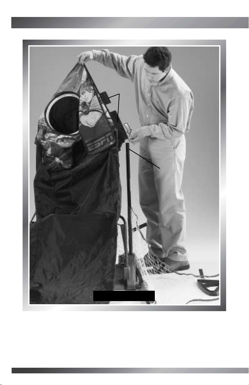
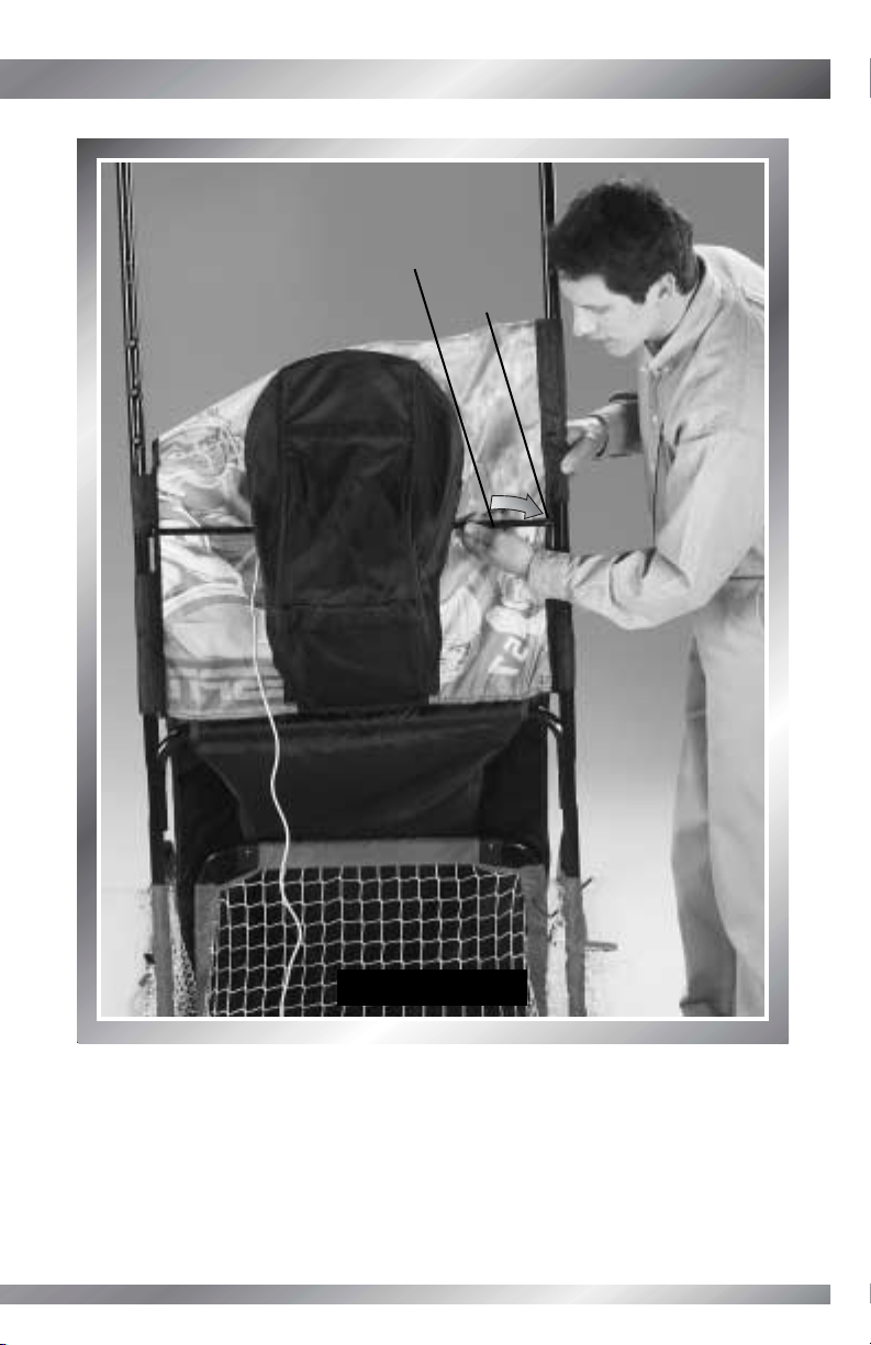
STEP 84
• Open the strap on the upper sleeve in
the chute.
• Insert the chute tab into the upper sleeve.
• Fasten the strap.
BACK VIEW
Upper
Sleeve
Chute Tab
Page 98

97
ASSEMBLY
ASSEMBLY
STEP 85
• Open the strap on the lower sleeve in
the chute.
• Insert the chute tab into the lower sleeve.
• Fasten the fastener.
BACK VIEW
Lower Sleeve
Chute Tab
Page 99

98
STEP 86
• Wrap a cable tie around the wires and the lower portion of the tube.
• Insert the end of the cable tie into the slot and pull to tighten. Cut the excess cable tie
with scissors.
Tip: Add a cable tie anywhere that you would like to fasten wires to tubes.
SIDE VIEW
Cable Tie
Page 100

99
ASSEMBLY
ASSEMBLY
STEP 87
• Insert and “snap” the shaft into the blade.
Shaft
Blade
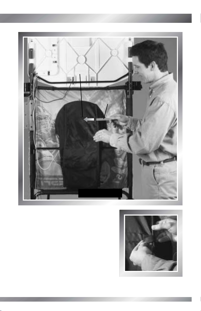
 Loading...