

Page 1
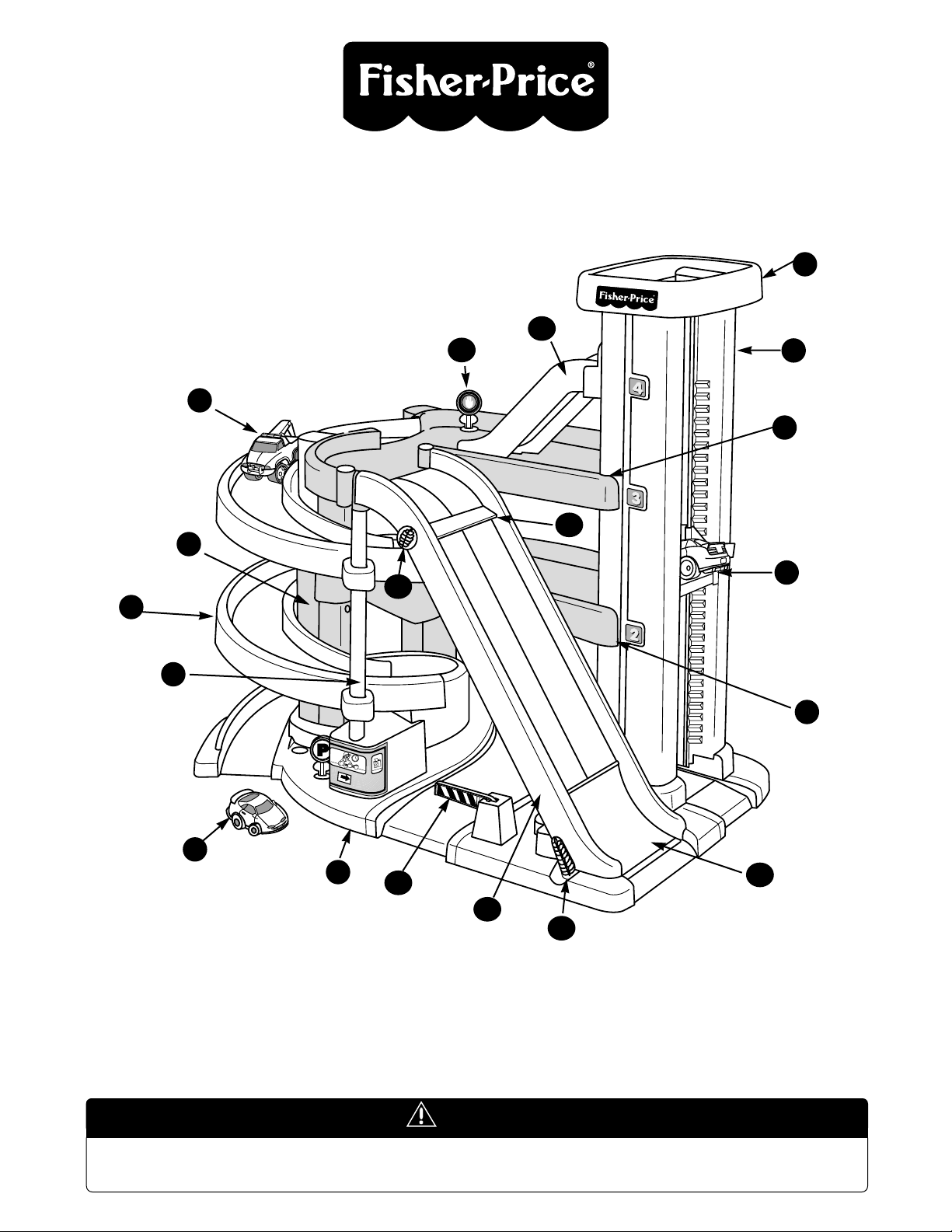
Big Action Garage
™
Please save these instructions for future reference.
Adult assembly is required.
Tool needed for assembly: Phillips Screwdriver.
Please read these instructions carefully and follow the assembly steps in order. The Big Action Garage
will not assemble correctly out of order and you may be unable to remove or disconnect
parts to correct the assembly.
Instructions
20
1
2
3
4
578910
11
12
13
17
15
26
25
6
14
Please keep small parts and plastic bags out of children’s reach.
CAUTION
Page 2
Speed Ramp
Speed Jump
Speed Jump Lever
Starting Gate
Starting Gate Pin
Elevator Gate - 3 (not shown)
Entrance Gate
Top Floor (Narrow)
Switching Gate (not shown)
Center Floor (Wide)
Switching Gate (not shown)
19
18
17
16
15
14
13
12
11
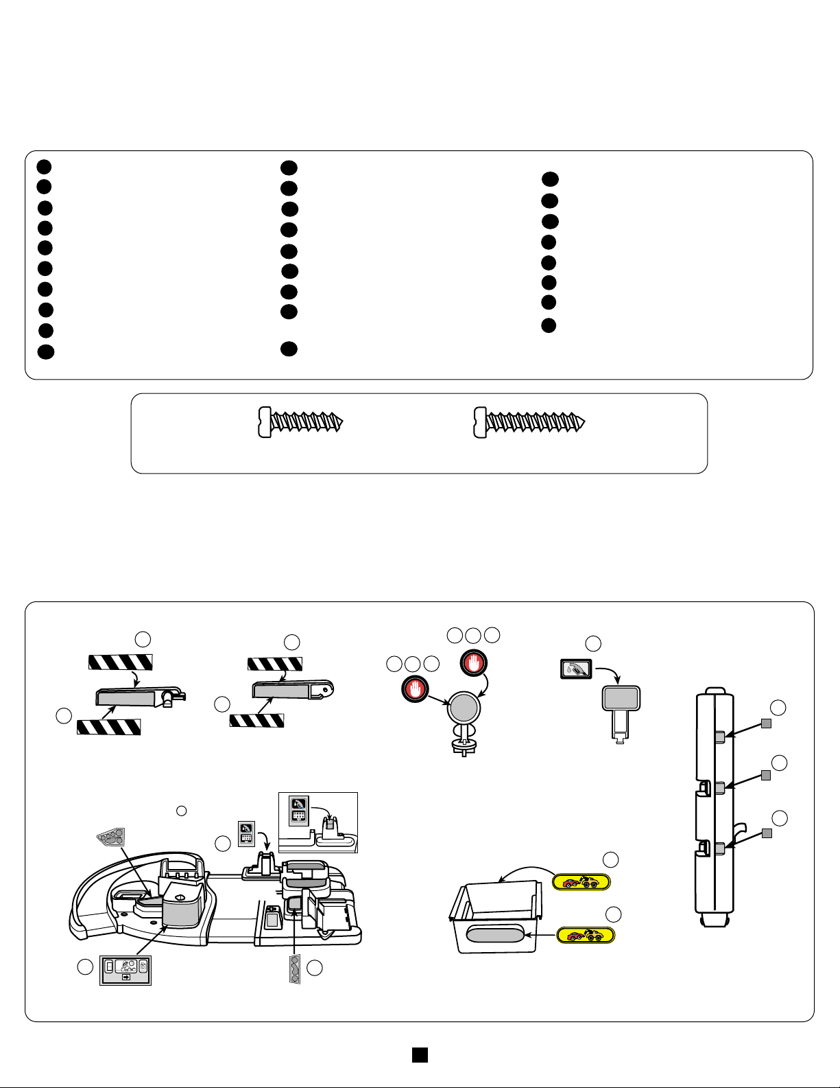
Label Decoration
• Apply the labels as shown in the illustrations below.
• Make sure the areas where the labels will be applied are clean and dry.
• Apply the top corners of a label first and smooth downward to remove any air bubbles.
• For best adhesion, try to avoid applying a label more than once.
Base
Center Floor
Top Floor - 1
Elevator Tower - 2
Tower Roof
Elevator
Side Support
Spiral Ramp - 2
Connector Tube
Hill Ramp
9
8
7
6
5
4
3
2
1
10
3
/4" Screw - 10
1" Screw - 4
Elevator Gate (3)
Entrance Gate
Round Sign (3)
(11, 12 not shown)
Elevator Tower (2)
Gas Pump Sign
Storage Drawer
Base
(Apply to recessed
area on Gas Pump)
4
3
2
Parts
Round Bottom Sign - 3
Gas Pump Sign (not shown)
Gas Pump Hose (not shown)
Storage Drawer (not shown)
Drawer Guide - 2 (not shown)
Tow Truck
Car - 2
HOT WHEELS™Track Connector
(not shown)
27
26
25
24
232221
20
©1996 Fisher-Price, Inc., East Aurora, New York 14052 77450 4 77450-0920
2
Thank you for purchasing the Fisher-Price Big Action Garage. With a drive-on working elevator, automatic elevator gates on each floor,
and a speed ramp for racing and speed jump excitement, the Big Action Garage is full of action. There’s even a gas pump to keep cars
on the go! We hope your child enjoys hours of fun with the Fisher-Price Big Action Garage™.
Message to Parents
1
1
2
2
3
4
5
6
6
7
8
9
11
12
4
11
12
13
10
10
(Shown Actual Size)
Page 3
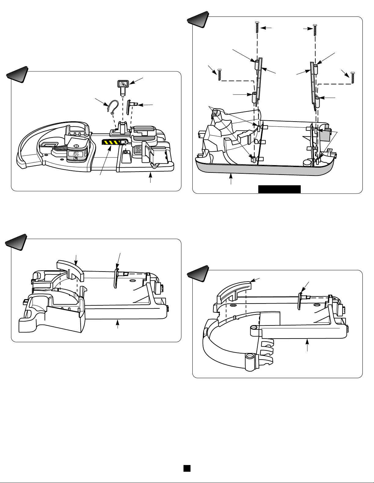
3
Assembly
• Position the base on a flat surface.
• Firmly snap the entrance gate, an elevator gate, the gas pump
sign and the gas pump hose into the base, as shown.
• Set the base aside.
• Turn the center floor upside down.
• Fit the holes on the drawer guides onto the pegs on the bottom
of the center floor. Make sure the drawer guides are pushed
down fully.
• Insert a
3
/4" screw into each of the four holes in the drawer
guides. Tighten the screws with a Phillips screwdriver. Do not
over-tighten.
• Set the center floor aside.
Base
Elevator Gate
Narrow
Switching
Gate
Top Floor
Elevator
Gate
Entrance Gate
Gas Pump Hose
Gas Pump
Sign
Drawer
Guides
Pegs
Hole
Hole
Pegs
Hole
Hole
Center Floor
Bottom View
IMPORTANT NOTE! Please read these instructions
carefully and follow the assembly steps in order.The
Big Action Garage will not assemble correctly out of order
and you may be unable to remove or disconnect parts to
correct the assembly.
• Position the top floor on a flat surface.
• Firmly snap the elevator gate into the top floor, as shown.
• Insert the narrow (top floor) switching gate into the recess in the
top floor.
• Press down firmly on the narrow switching gate so that it is fully
inserted into the top floor.
• Set the top floor aside.
• Position the center floor on a flat surface.
• Firmly snap an elevator gate into the center floor, as shown.
• There are two switching gates. Separate the wide (center floor)
switching gate from the narrow (top floor) switching gate.
• Insert the wide (center floor) switching gate into the recess in
the center floor.
• Press down firmly on the wide switching gate so that it is fully
inserted into the center floor.
Wide Switching
Gate
Elevator Gate
Center Floor
1
2
3
4
3
/4" Screw
3
/4" Screws
3
/4" Screw
Page 4

4
• Position the side support on a flat surface.
• Insert four
3
/4" screws into the side support. Tighten the screws
with a Phillips screwdriver. Do not over-tighten.
• Fit the square openings on the underside of the top floor onto
the posts on the side support.
• Make sure the rectangular tab on the top floor inserts into the
rectangular opening on the side support upper crossbar.
• Push down firmly on the top floor to snap it onto the side
support.
Helpful Hint: You may need to push down near each of the posts
and the tab to fully snap each one into the side support. You will
hear a “click” when each post and the tab snaps into the side
support.
• Pull up on the top floor to make sure it is secured to the side
support.
Top Floor
Side
Support
Leg
Opening
Middle
Ta b
Lower
Crossbar
Center Floor
End Tab
End Tab
Square Opening
Square Opening
Post
Post
Side
Support
Upper
Crossbar
Rectangular
Opening
Rectangular
Ta b
Side Support
3
/4" Screws
3
/4" Screws
Opening
Opening
• Insert the middle tab on the center floor into the opening in the
side support lower crossbar.
• Insert the end tabs on the center floor into the openings in the
side support legs.
• Push down firmly on the center floor to snap it into the side
support.
Helpful Hint: You may need to push down near each of the three
tabs to snap each one into the side support. You will hear a
“click” when each tab snaps into the side support.
• Pull up on the center floor to make sure it is secured to the side
support.
• Set the side support assembly aside.
576
• Place the elevator tower with the rails on a flat surface, with the
rails facing up.
• Place the other elevator tower on the flat surface, as shown.
• Insert two 1" screws into each elevator tower, as shown.
Tighten the screws with a Phillips screwdriver. Do not
over-tighten.
• With the elevator at an angle, fit the grooves in the elevator
onto the rails at the bottom of the elevator tower .
• Rotate the elevator down to fully seat the
grooves onto the elevator tower rails.
• Slide the elevator to the middle of the elevator tower .
3
2
1
Bottom of
Elevator
To we r
Elevator
Rails
1" Screws
Elevator
Towers
1
2
3
1" Screws
8
Page 5

5
Connector
Tube
U-Shaped
Rings
Top Floor
Recess
Spiral Ramp
Tower Roof
Elevator
To we r
Elevator
To we r
Tabs
Tabs
Spiral
Ramps
Rectangular
Openings
Rectangular
Openings
Center
Floor
Top Floor
Rectangular
Ta b
Rectangular
Ta b
Rectangular
Opening
Rectangular
Opening
Side
Support
Tabs
Tabs
Elevator Tower
Rectangular
Openings
Center Floor
Top Floor
• Insert and firmly snap the tabs on the top and center floors into
the rectangular openings in the sides of the elevator tower.You
will hear a “click” when each tab snaps into the elevator tower.
• Pull on the elevator tower to make sure it is secured to the top
and center floor.
• Lay the assembly on its side with the bottom facing you.
• Insert the connector tube up through the U-shaped rings on the
ends of the upper and lower spiral ramps.
• Insert the top of the connector tube into the recess in the top
floor.
• Insert a
3
/4" screw through each spiral ramp and into the side
support, as shown. Tighten the screws with a Phillips
screwdriver. Do not over-tighten.
• Turn the assembly upright.
3
/4"
Screws
• Stand both elevator towers upright, as shown. The short,
rectangular tabs are at the top of the elevator towers.
• Fit the tower roof onto the elevator towers.
• Push down firmly near each of the rectangular tabs to snap the
tower roof onto the elevator towers. You will hear a “click” when
each tab snaps into the tower roof.
• Pull up on the tower roof to make sure it is secured to the
elevator towers.
• Turn the assembly so that the side support faces you.
• Insert and firmly snap the tabs on the ends of a spiral ramp into
the rectangular openings in the center floor.
• Insert and firmly snap the tabs on the ends of the other
spiral ramp into the rectangular openings in the top floor.
• Pull on each spiral ramp to make sure it is secured to the top or
center floor.
Bottom View
Side View
10
12
11
9
Page 6

6
Elevator Tower
Side Support
Legs
Connector
Tube
To we r
Roof
Base
• Remove the instructional labels from the base and discard
them.
• Position the ramp assembly over the base. Make sure the
elevator tower, side support legs, and connector tube align with
the recesses on the base, as shown.
• Push down firmly on the tower roof to snap the elevator tower
into the base.
• Push down firmly on the top of each side support leg to snap
the side support into the base.
• Pull up on the elevator tower and top floor to make sure the
ramp assembly is secured to the base.
Spiral
Ramp
Push Here
Spiral
Ramp
• Push down firmly at the base of the upper spiral ramp to snap it
into the center floor.
• Push down firmly at the base of the lower spiral ramp to snap it
into the base.
Helpful Hint: You will hear a “click” when each tab on the
spiral ramps snaps into the center floor or base.
• Pull up on each spiral ramp to make sure it is secured to the
garage floor.
Tabs
Hill Track
Top Floor
Elevator
To we r
Tabs
Slots
• Position the speed ramp so that the underside is facing you.
• Insert the jump lever up through the slot in the speed ramp, as
shown .
• Turn the speed ramp so that the top faces you.
• Insert the pin on the end of the jump lever into the hole in the
speed ramp .
16B
16A
Jump
Lever
Jump
Lever
Hole
Pin
Slot
Speed Ramp
• Insert and firmly snap the tabs on the top of the hill track into
the slots in the elevator tower.You will hear a “click” when each
tab snaps into the elevator tower.
• Insert and firmly snap the tabs at the bottom of the hill ramp
into the slots in the top floor.You will hear a “click” when each
tab snaps into the top floor.
• Pull up on the hill track to make sure it is secured to the
elevator tower and the top floor.
• Insert the pins on the sides of the speed jump into the holes in
the sides of the speed ramp.
Pin
Pin
Hole
Hole
Speed Jump
Speed Ramp
14
15
16A
16B
17
13
Page 7

7
• Slide and firmly snap the speed ramp onto the tabs on the top
floor.
• Insert and firmly snap the tabs on the bottom of the speed
ramp into the slots on the base.
• Pull up on the speed ramp to make sure it is secured to the top
floor and base.
• Position the Big Action Garage so that the back of the garage
faces you.
• Align the side rails on the storage drawer with the drawer guides
on the underside of the center floor.
• Slide the storage drawer underneath the center floor.
Speed
Ramp
Tabs
Tabs
Slots
Base
Top Floor
Elevator
Platform
Side
Rail
Side Rail
Storage Drawer
Center Floor
Drawer
Guide
Drawer
Guide
• Drive a vehicle onto the elevator platform and raise or lower the
elevator to any of the four levels. The elevator gates will automatically open to let you drive through!
Features
Elevator
Back View
Front View
• Insert the tab on the end of the starting gate into the hole in the
top of the speed ramp.
• Lower the starting gate into the recess on the speed ramp.
• Insert the starting gate pin through the side of the speed
ramp and into the starting gate as shown. Make sure that the
hook on the end of the starting gate pin is upward.
• Rotate the starting gate pin to lower the starting gate.
Ta b
Starting Gate Pin
Recess
Upper
Hole
Starting Gate
Hook
19
20
18
Page 8

8
• To route traffic down the hill ramp and onto the speed ramp,
raise the top floor switching gate by pushing up on the
switching gate tab on the underside of the top floor.
• To detour vehicles to the center floor, keep the top and
center floor switching gates lowered.
• To route traffic down both spiral ramps to the ground level, keep
the top floor switching gate lowered and raise the center floor
switching gate.
• Rotate the starting gate knob counter-clockwise to raise the
speed ramp starting gate.
• Place one or two vehicles behind the starting gate and rotate
the starting gate pin clockwise to lower the starting gate. Watch
them race down the speed ramp!
• For added excitement, rotate the jump lever at the bottom of the
speed ramp clockwise to raise the speed jump and watch the
cars fly!
• Insert the round plugs on the bottom of the road signs into any
of the round holes on the base, center or top floors.
• Attach the HOT WHEELS™ Track Connector anyplace on the
top or center floors to connect your own HOT WHEELS™
race track to the Big Action Garage.
Switching Gates
Speed Ramp
Signs
Connect to HOT WHEELS™ Race Track!
Back View
Switching
Gate Tab
Switching
Gate Tab
HOT WHEELS™
Tr ac k
Tr ac k
Connector
Starting
Gate Knob
Jump Lever
HOT WHEELS™ and associated trademarks are owned and used under
license from Mattel, Inc. © 1995 Mattel, Inc. All Rights Reserved.
Front View
Questions? We’d like to hear from you!
Call Fisher-Price Consumer Affairs, toll-free at
1-800-432-KIDS, 8 AM - 6 PM EST Monday thruough Friday,
9 AM - 5 PM EST Saturday. Hearing-impaired consumers using
TTY/TDD equipment, please call 1-800-382-7470.
Or, write to: Fisher-Price Consumer Affairs, 636 Girard Avenue,
East Aurora, New York 14052.
If you have any questions about this product: In Canada, call 1-800-567-7724, or write to:
Mattel/Fisher-Price, 6155 Freemont Blvd., Mississauga, Ontario L5R 3W2.
In Great Britain, telephone 01734 770488. In Australia, call the Fisher-Price Australian
Consumer Advisory Service toll-free at 1-800-800-812, or write to: Fisher-Price, Mattel
Pty.Limited, 461 Plummer Street, Por t Melbourne, Victoria 3207.
 Loading...