

Page 1
READ ENTIRE INSTRUCTIONS
BEFORE INSTALLATION.
READ AND SAVE THESE INSTRUCTIONS
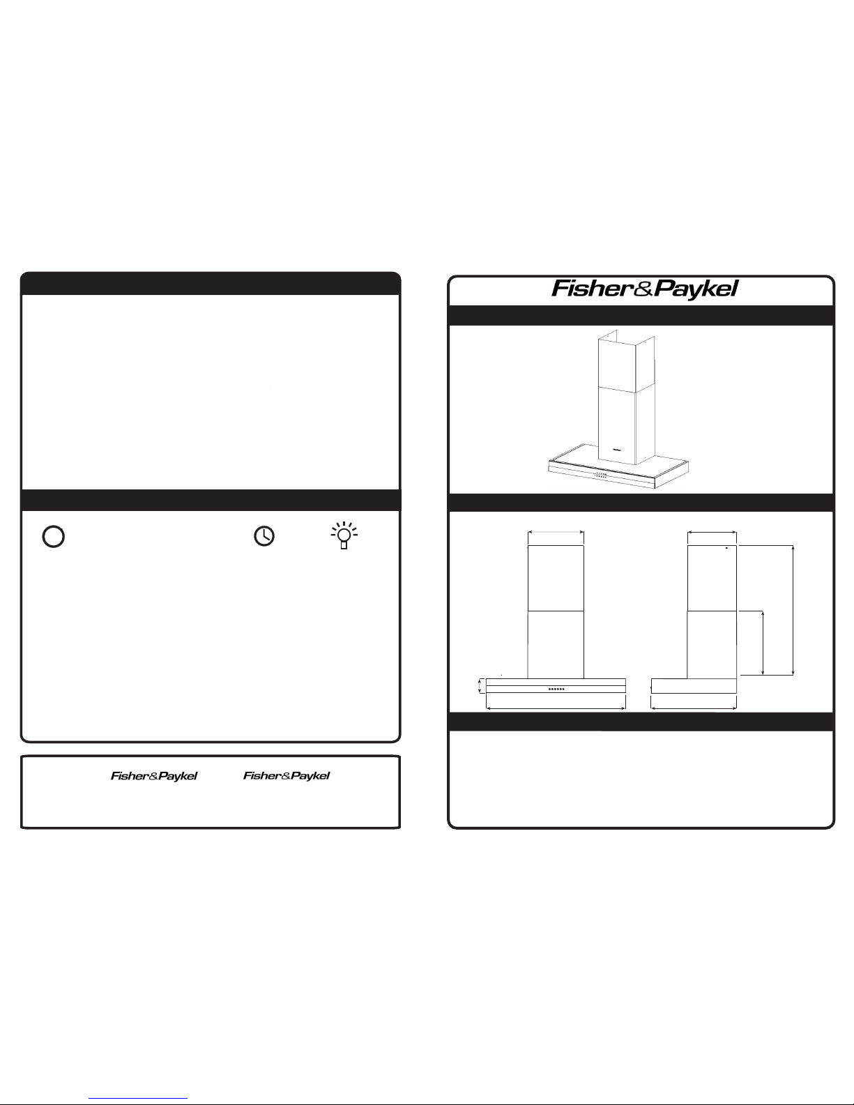
PRODUCT DIMENSIONS
PRE-INSTALLATION INSTRUCTIONS
Thank you for purchasing a quality stainless steel canopy rangehood. We have a high
standard of quality control and each rangehood is tested and approved before it leaves the factory.
Installation work and electrical wiring must be done by qualified person(s) in accordance with all
applicable codes and standards, including fire-rated construction. When cutting or drilling into wall or
ceiling, do not damage electrical wiring and other hidden utilities.
Use this unit only in the manner intended by the manufacturer. If you have any questions, contact
the manufacturer.
The canopy is heavy: overall weight 50.6 lbs (23kg). Please ensure adequate care when installing the
canopy to prevent personal injury. The canopy must be installed onto a solid wall or solid studs.
Designer Canopy
88507 HC36DXB1
35 1/3” (898mm)
12 ~ 1/2”
(317mm)
2 ~ 13/16”
(72mm)
10 ~ 7/8”
(276mm)
19 ~ 9/16”
(497mm)
min 23 ~ 5/8”
(600mm)
max 32 ~ 1/2”
(825mm)
20” (507mm)
400030_A
Electrical Rating:
120V 60Hz 285W 3,5A
This appliance is not intended for use by young children or infirm persons without supervision.
Young children should be supervised to ensure that they do not play with the appliance.
Upon installation the appliance must be positioned so that the plug is accessible.
There should be adequate ventilation of the room when the rangehood is used at the same time as
appliances burning gas or other fuels.
You must read the details concerning the method and frequency of cleaning.
There is a fire risk if cleaning is not carried out in accordance with the instructions.
Exhaust air must not be discharged into an existing flue used for exhausting fumes from appliances
burning gas or other fuels.
The recommended minimum distance between the hob surface and the lowest part of the rangehood
is 29.5” (750mm).
Attention should be given to ensure that any applicable regulations concerning the discharge of
exhaust air is fulfilled.
If the supply cord of this equipment is damaged, it must only be replaced by the manufacturer or
its service agent, or a similarly qualified person in order to avoid a hazard.
WARNING - TO REDUCE THE RISK OF FIRE, USE ONLY METAL DUCTWORK.
WARNINGS
CLEANING INSTRUCTIONS
Care and attention should always be taken when cooking with oils, alcohol, etc, which give off
flammable vapours. Pre-used oil is especially dangerous in this respect. Do not use an
uncovered electrical grill. Particular care must be taken with grease filters which must be
periodically cleaned, at least every two months. Remove the grease filters and wash them
either by hand or in the dishwasher using mild detergent. Use lukewarm water and mild
detergent to clean stainless steel components. In high humidity and coastal environments,
cleaning should be carried out frequently. CAUTION: Never use abrasive or oil based liquid cleaners.
OPERATION INSTRUCTIONS
CONTROL PANEL
Delay switch - Fan will remain on at low, mid or high speed for 5 minutes before switching off
automatically.
I
II
III
Fan On/Off Mid Speed High Speed Delay Switch Light On/Off
I
MANUFACTURED FOR
BY:
ROBINHOOD LIMITED
6 ZELANIAN DRIVE, EAST TAMAKI
AUCKLAND, NEW ZEALAND
Fisher & Paykel Appliances, Inc.
27 Hubble, Irvine, CA 92618
Toll Free 1-888-9-FNP-USA (1-888-9-367-872)
Page 2
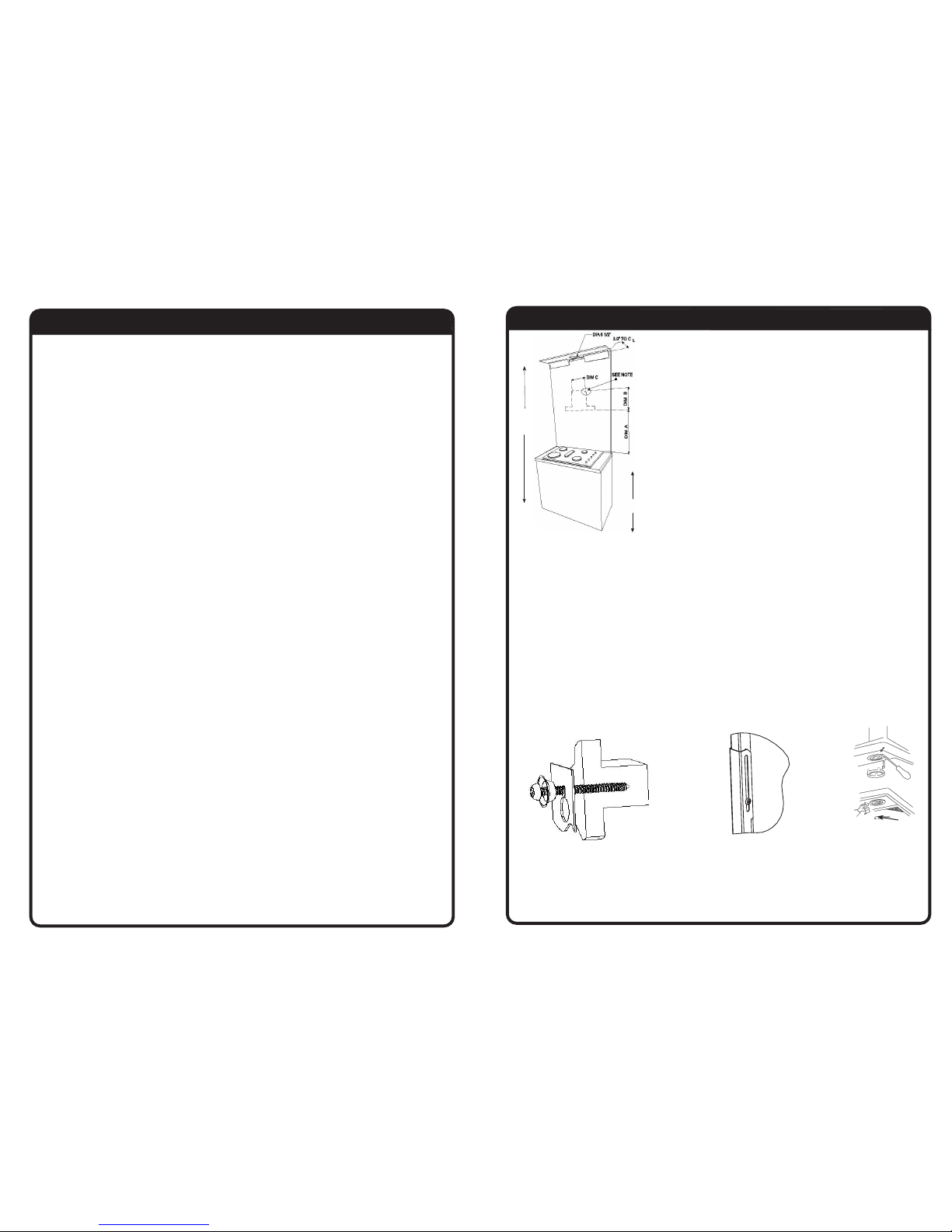
DUCTING: Ducting accessories are not supplied. For ducting it is recommended you use 6” (150mm)
diameter rigid / semi rigid ducting. This will require a 6.5” (165mm) hole in the ceiling/wall.
NOTE: Fixing to a stud is recommended.
1. Pre drill pilot hole 1/8” (3mm) diameter at dimensions C and B. B=9” (225mm) and
C=10.25” (260mm).
2. Loosly fix the 12 x 2” screws and 2 x cup washers in position, check with a spirit level across
the screws to ensure they are level.
3. Mark the position of the decorative chimney at the ceiling and wall. Cut the cornice moulding
away as required, to enable the chimney to fit flush against the wall and ceiling.
4. Mark and cut out the hole in the ceiling/wall to fit the ducting (6.5” (165mm) dia.). This is
positioned centrally above the canopy hood and 3.9” (100mm) from the wall (for ceiling option).
5. Using the screws supplied, fix the chimney bracket to the wall/ceiling, checking that it is
centrally located above the canopy.
6. Remove the protective plastic covering from all parts including the filters. Fit the canopy hood
on the mounting screws, tighten screws (diag.2).
7. Connect to the power supply and switch on the power to the canopy hood. Check the function of
the canopy hood. Connect and secure the ducting (use duct tape if required).
8. Assemble the chimney pieces to a height that best suits the installation, leave these screws
loose so that the chimney is free to extend by a few mm (diag.3). Place the two pieces onto
the canopy top and secure the lower part to the canopy sides. Extend the upper chimney to the
ceiling and secure in place with two screws supplied.
WARNING - TO REDUCE THE RISK OF FIRE, USE ONLY METAL DUCTWORK.
WARNING - GROUNDING INSTRUCTIONS
This appliance must be grounded. In the event of an electrical short circuit, grounding reduces
the risk of electrical shock by providing an escape wire for the electric current. This appliance
is equipped with a cord having a grounding wire with a grounding plug. To provide protection
against electric shock the plug must only be plugged into an outlet that is properly installed and
grounded.
WARNING - Improper grounding can result in a risk of electric shock.
Appliance to be connected to a 15/20A circuit breaker.
Consult a qualified electrician if the grounding instructions are not completely understood, or if
doubt exists as to whether the appliance is properly grounded.
Do not use an extension cord. If the power supply cord is too short, have a qualified electrician
install an outlet near the appliance.
CAUTION: To reduce the risk of fire and to properly exhaust air, be sure to duct air outside - Do
not vent exhaust air into spaces within walls or ceilings or into attics, crawl spaces or garages.
CAUTION: For General Ventilating Use Only. Do Not Use To Exhaust Hazardous Or Explosive
Materials And Vapours.
CAUTION: To Reduce The Risk Of Fire Or Electric Shock, Install This Rangehood Only With Integral
Blowers Manufactured By Robinhood, Model 104612.
WARNING: To Reduce The Risk Of Fire Or Electric Shock, Do Not Use This Fan With Any Solid-State
Speed Control Device.
WARNING - TO REDUCE THE RISK OF A RANGE TOP GREASE FIRE:
a) Never have surface units unattended at high settings. Boilovers cause smoking and greasy
spillovers that may ignite. Heat oils slowly on low or medium settings.
b) Always turn hood ON when cooking at high heat or when flambéing food (ie crepes suzette, cherries
jubilee, pepercorn beef flambé etc).
c) Clean ventilating fans frequently. Grease should not be allowed to accumulate on fan or filters.
d) Use proper pan size. Always use cookware appropriate for the size of the surface element.
WARNING - TO REDUCE THE RISK OF INJURY TO THE PERSONS IN THE EVENT OF A RANGE TOP
GREASE FIRE, OBSERVE THE FOLLOWING*:
a) SMOTHER FLAMES with a close-fitting lid, cookie sheet, or metal tray and then turn off the burner
BE CAREFUL TO PREVENT BURNS. If the flames do not go out immediately, EVACUATE AND CALL
THE FIRE DEPARTMENT.
b) NEVER PICK UP A FLAMING PAN - you may be burned.
c) DO NOT USE WATER, including wet dishcloths or towels - a violent steam explosion will result.
d) Use an extinguisher ONLY if:
1) You know you have a Class ABC extinguisher and you already know how to operate it.
2) The fire is small and contained in the area where it started.
3) The fire department is being called.
4) You can fight the fire with your back to an exit.
* Based on “Kitchen Firesafety Tips” published by NFPA.
NOTE: Stainless steel is very easily damaged during installation if abraided
or knocked by tools.
Warning - Remove transport tape from the lights and the filters
before use.
Read the instructions before starting the assembly. Remove the filters to
allow access to wall mounting holes.
The unit is designed for ceilings 7’ 6” to 8’ 10” (2290 to 2690mm) high.
The chimney is telescopic and is designed to adjust between 23~5/8” and
32~1/2” (600 to825mm).
Ascertain the desired installation height of the canopy.
NOTE: Minimum installation height 29.5” (750mm).
RECIRCULATION: For recirculation, do not cut 6.5” (165mm) hole into the
wall/ceiling and purchase the charcoal filters and recirculation kit 1744.
The recirculation kit must be used to channel the air to the top of the flue.
For other accessories, parts and service, please contact your local supplier
or approved service agent.
INSTALLATION INSTRUCTIONS
Disconnect the power to the rangehood. Using a small bladed screwdriver prise off the light cover. If
the bulb is hot use a cloth to remove the bulb. Replace with a new bulb using a cloth. Do not
touch the new bulb with your fingers as the grease from your fingers will crack the bulb when it is
switched on. “Snap” the cover back in place. A halogen bulb 12Volt/20Watt is required.
For other accessories, parts or service, please contact your local supplier (Refer to the Warranty
Certificate).
LIGHT REPLACEMENT (See diag. 4)
diag.4
BULB
Ceiling height
7’6” to 8’10”
(2290 to 2690)
Cooking surface
36” (914)
diag.2 diag.3
WARNINGS
diag.1
 Loading...